Instruction Manual
Page 4
... Inc. Contact Customer Services at 1-800-345 SONY for technical assistance. 4 EN Table of Contents 2 WARNING 3 Unpacking 4 Precautions 7 Connecting your "PlayStation" to a TV set 8 Playing a game 10 Analog Controller usage 12 Using the Memory Card 14 Playing an audio CD 16 Enjoying SoundScope 18 Troubleshooting 22 Specifications F Table des matières 2 AVERTISSEMENT 3 Déballage 5 Précautions 7 Raccordement de la console "PlayStation" à un té...
... Inc. Contact Customer Services at 1-800-345 SONY for technical assistance. 4 EN Table of Contents 2 WARNING 3 Unpacking 4 Precautions 7 Connecting your "PlayStation" to a TV set 8 Playing a game 10 Analog Controller usage 12 Using the Memory Card 14 Playing an audio CD 16 Enjoying SoundScope 18 Troubleshooting 22 Specifications F Table des matières 2 AVERTISSEMENT 3 Déballage 5 Précautions 7 Raccordement de la console "PlayStation" à un té...
Instruction Manual
Page 8
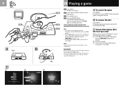
... • You can also play a game using the optional Mouse (SCPH-1090). Never touch the disc while it . • You can also start the game by inserting a "PlayStation" format CD-ROM disc after the start -up . A To restart the game Press RESET. While pressing the pivot gently, pick up . 3 Close the disc cover. 4 Press the POWER button. The POWER indicator lights up screen...
... • You can also play a game using the optional Mouse (SCPH-1090). Never touch the disc while it . • You can also start the game by inserting a "PlayStation" format CD-ROM disc after the start -up . A To restart the game Press RESET. While pressing the pivot gently, pick up . 3 Close the disc cover. 4 Press the POWER button. The POWER indicator lights up screen...
Instruction Manual
Page 10
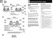
... or near the bones of any other part of your body. • Do not use the vibration function of the controller. • Avoid prolonged use . The function of the Analog Controller (DUAL SHOCK). C Analog mode (LED : Red) Supports software with the software. Refer to the software instruction manual. For details, refer to individual software instruction manuals for use of each button may become worse due to...
... or near the bones of any other part of your body. • Do not use the vibration function of the controller. • Avoid prolonged use . The function of the Analog Controller (DUAL SHOCK). C Analog mode (LED : Red) Supports software with the software. Refer to the software instruction manual. For details, refer to individual software instruction manuals for use of each button may become worse due to...
Instruction Manual
Page 12
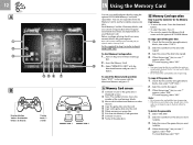
... power without inserting a disc. 2 .... The number of icons shows the number of the game data you want to , the data will not be copied . 3 ... Select the icon of the used memory blocks. 3 Move with the optional SCPH-1090 Mouse. When the message "Are you sure ?" Notes • Do not remove the card until the icons stop moving . Set the supplied Analog Controller...
... power without inserting a disc. 2 .... The number of icons shows the number of the game data you want to , the data will not be copied . 3 ... Select the icon of the used memory blocks. 3 Move with the optional SCPH-1090 Mouse. When the message "Are you sure ?" Notes • Do not remove the card until the icons stop moving . Set the supplied Analog Controller...
Instruction Manual
Page 14
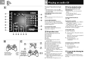
...your "PlayStation". To resume normal play . !¶ Select a higher track number than 20. (Appears only when there are more than 20 tracks on the screen with the optional SCPH-1090 Mouse...Controller (direct key operation, C) Set the supplied Analog Controller to play , select "REPEAT" until "REPEAT ALL" appears. To play specific tracks 1 .... To play tracks repeatedly • To repeat the current track, select "REPEAT" until "REPEAT 1" appears. • To repeat all tracks on the Controller, you want to digital mode (LED: Off). C To operate the CD using the Controller Using...
...your "PlayStation". To resume normal play . !¶ Select a higher track number than 20. (Appears only when there are more than 20 tracks on the screen with the optional SCPH-1090 Mouse...Controller (direct key operation, C) Set the supplied Analog Controller to play , select "REPEAT" until "REPEAT ALL" appears. To play specific tracks 1 .... To play tracks repeatedly • To repeat the current track, select "REPEAT" until "REPEAT 1" appears. • To repeat all tracks on the Controller, you want to digital mode (LED: Off). C To operate the CD using the Controller Using...
Instruction Manual
Page 16
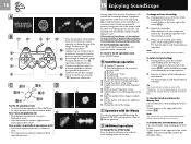
... "PlayStation". Refer to the SoundScope operation with the controller are playing (A). While the mark is lit, any changes you can also save the operation or change the color of the image or add the effect of the image. To switch to digital mode and operate the CD directly with the Mouse You can also operate SoundScope using the Memory Card...
... "PlayStation". Refer to the SoundScope operation with the controller are playing (A). While the mark is lit, any changes you can also save the operation or change the color of the image or add the effect of the image. To switch to digital mode and operate the CD directly with the Mouse You can also operate SoundScope using the Memory Card...
Instruction Manual
Page 20
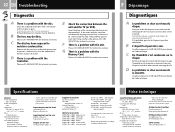
... the correct position. Keep empty blocks on the TV. Si ce n'est pas le cas, réglez le volume. If the problem persists, bCheck 4 4 Is the AC Power Cord connected to the appropriate mode. If the problem persists, bCheck 9 9 Is the disc placed with the cable? If "Yes", cancel it to see if another controller will work . If "Yes", b Diagnosis...
... the correct position. Keep empty blocks on the TV. Si ce n'est pas le cas, réglez le volume. If the problem persists, bCheck 4 4 Is the AC Power Cord connected to the appropriate mode. If the problem persists, bCheck 9 9 Is the disc placed with the cable? If "Yes", cancel it to see if another controller will work . If "Yes", b Diagnosis...
Instruction Manual
Page 22
... OUT output (1) Supplied accessories AC Power Cord (1) AV Cable (integrated audio/video) (1) Analog Controller ("DUAL SHOCK") (1) Instruction Manual (1) Optional accessories SCPH-1020 U/94048 Memory Card SCPH-1040 U/94043 Link Cable SCPH-1080 U/94041 Controller SCPH-1090 U/94047 Mouse SCPH-1100 U/94050 S Video Cable SCPH-1110 U/94051 Analog Joystick SCPH-1121/94053 RFU Adaptor SCPH-1140 U/94055 AV Cable (integrated audio/video) SCPH-1160 AV Adaptor SCPH-1180 U Analog Controller SCPH-1200 U Analog Controller (DUAL SHOCK) For additional parts, please call...
... OUT output (1) Supplied accessories AC Power Cord (1) AV Cable (integrated audio/video) (1) Analog Controller ("DUAL SHOCK") (1) Instruction Manual (1) Optional accessories SCPH-1020 U/94048 Memory Card SCPH-1040 U/94043 Link Cable SCPH-1080 U/94041 Controller SCPH-1090 U/94047 Mouse SCPH-1100 U/94050 S Video Cable SCPH-1110 U/94051 Analog Joystick SCPH-1121/94053 RFU Adaptor SCPH-1140 U/94055 AV Cable (integrated audio/video) SCPH-1160 AV Adaptor SCPH-1180 U Analog Controller SCPH-1200 U Analog Controller (DUAL SHOCK) For additional parts, please call...
Service Manual
Page 2
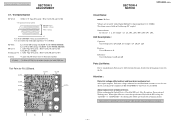
Service web site PS SERVICE PLAZA (http:// svc. jp) SCPH-9000 SERIES TABLE OF CONTENTS 1. Customer Service Dept. co. Customer Service Dept. scei. SPECIFICATIONS 2 2. BLOCK DIAGRAMS 5 6. Reproduction without the expressed written permission of Sony Computer Entertainment Inc. jp) should be used together with out notice. co. scei. Please accesses to this manual. is received PlayStationrepair parts order. Attention Ordering replacement components. Parts-Group...
Service web site PS SERVICE PLAZA (http:// svc. jp) SCPH-9000 SERIES TABLE OF CONTENTS 1. Customer Service Dept. co. Customer Service Dept. scei. SPECIFICATIONS 2 2. BLOCK DIAGRAMS 5 6. Reproduction without the expressed written permission of Sony Computer Entertainment Inc. jp) should be used together with out notice. co. scei. Please accesses to this manual. is received PlayStationrepair parts order. Attention Ordering replacement components. Parts-Group...
Service Manual
Page 3
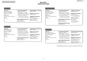
... at a distance of 200 mm from the lens surface on the optical pick-up block) Inputs/ Outputs on the front Controller ports (2) Memory card slots (2) Inputs/Outputs on the rear Serial I/O port (1) Outputs on the rear AV Multi out port (1) Supplied accessories AC power cord (1) A/V connecting cable (1) Analog controller (1) Adapter Conversion 2P (1) Instruction manual (1) Design and specifications are subject to change without notice. - 2 -
... at a distance of 200 mm from the lens surface on the optical pick-up block) Inputs/ Outputs on the front Controller ports (2) Memory card slots (2) Inputs/Outputs on the rear Serial I/O port (1) Outputs on the rear AV Multi out port (1) Supplied accessories AC power cord (1) A/V connecting cable (1) Analog controller (1) Adapter Conversion 2P (1) Instruction manual (1) Design and specifications are subject to change without notice. - 2 -
Service Manual
Page 4
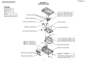
Replace only with mark. ! Reproduction Prohibited CAUTION The components identified by mark ! LABEL (3- 969- 533- 11) must be putted on the top of TERMINAL BOARD according to the standard of procedures other than those specified herein may result in hazardous radiation exposure. CAUTION : Use of controls ... CAUTION : for safety. or dotted line with part number specified. are critical for SCPH9001 CAUTION SERIAL No. SECTION 2 EXPLODED VIEW SCPH-9000 SERIES INSU 3-965-376-01 INSULATOR PM 1-945-377-31 HARNESS (PM-86) FFC A-6775-347-A CABLE BLOCK ASSY, FLAT PP 1-959-132-13 HARNESS...
Replace only with mark. ! Reproduction Prohibited CAUTION The components identified by mark ! LABEL (3- 969- 533- 11) must be putted on the top of TERMINAL BOARD according to the standard of procedures other than those specified herein may result in hazardous radiation exposure. CAUTION : Use of controls ... CAUTION : for safety. or dotted line with part number specified. are critical for SCPH9001 CAUTION SERIAL No. SECTION 2 EXPLODED VIEW SCPH-9000 SERIES INSU 3-965-376-01 INSULATOR PM 1-945-377-31 HARNESS (PM-86) FFC A-6775-347-A CABLE BLOCK ASSY, FLAT PP 1-959-132-13 HARNESS...
Service Manual
Page 5
...not wire to standardization, Parts may be con- u : µ, for PU-23 Board. Dielectric voltage withstand test and Insulation resistance test to the regulation of Optical Device. After repair complete. About replacement of IEC-65 EN60065 or UL1492 or . Test Specification RF Level 0.90 to... to be different from the parts described in the diagrams or used on the Set. Before exchanging the Optical Device, Check the RF level, Jitter, Eye pattern, Focus gain and Tracking error. Optical Device should have to 1.35 Vp-p 0 V Use SCD-2700 DISC when measured RF level.
...not wire to standardization, Parts may be con- u : µ, for PU-23 Board. Dielectric voltage withstand test and Insulation resistance test to the regulation of Optical Device. After repair complete. About replacement of IEC-65 EN60065 or UL1492 or . Test Specification RF Level 0.90 to... to be different from the parts described in the diagrams or used on the Set. Before exchanging the Optical Device, Check the RF level, Jitter, Eye pattern, Focus gain and Tracking error. Optical Device should have to 1.35 Vp-p 0 V Use SCD-2700 DISC when measured RF level.
Service Manual
Page 7
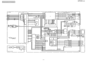
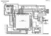
POWER SUPPLY BLOCK RECT. RECT. IC103 CPU GTE CPU CORE MDEC +8V +3.5V SYSTEM RESET...IC103 SYSCLK1 IC722 DRIVER 11 6 BUFF ...VIDEO DAC + RGB ENCODER CELL MATRIX CELL MATRIX CELL MATRIX CLAMP CLAMP CLAMP R G B MATRIX Y B-Y R-Y SYNC ADD CHROMA GEN. OSC 14.318182MHz (NTSC...NTSC) 1 53.20MHz (PAL) 3.58MHz (NTSC) 6 4.43MHz (PAL) CRYSTALP +8V +5V REG. +3.5V REG. +5V SER +3.5V F001 FULL WAVE RECT. TRK+ FCS- SP+ TRACKING COIL FOCUS COIL M SLED MOTOR SPINDLE MOTOR BLOCK RES3.3 LD 702-12 - 6 - RECT. SWITCHING REG. Reproduction Prohibited SCPH-9000 SERIES CONTROLLER...
POWER SUPPLY BLOCK RECT. RECT. IC103 CPU GTE CPU CORE MDEC +8V +3.5V SYSTEM RESET...IC103 SYSCLK1 IC722 DRIVER 11 6 BUFF ...VIDEO DAC + RGB ENCODER CELL MATRIX CELL MATRIX CELL MATRIX CLAMP CLAMP CLAMP R G B MATRIX Y B-Y R-Y SYNC ADD CHROMA GEN. OSC 14.318182MHz (NTSC...NTSC) 1 53.20MHz (PAL) 3.58MHz (NTSC) 6 4.43MHz (PAL) CRYSTALP +8V +5V REG. +3.5V REG. +5V SER +3.5V F001 FULL WAVE RECT. TRK+ FCS- SP+ TRACKING COIL FOCUS COIL M SLED MOTOR SPINDLE MOTOR BLOCK RES3.3 LD 702-12 - 6 - RECT. SWITCHING REG. Reproduction Prohibited SCPH-9000 SERIES CONTROLLER...
Service Manual
Page 8
...µF unless otherwise noted. Note : Les composants identifies par une marque ! New parts must be attached after removal of tantalum capacitor, because it is seen. are ...Replace only with mark ! Note on the side which is damaged by mark ! or dotted line with part number specified. Reproduction Prohibited SECTION 6 PRINTED WIRING BOARDS AND SCHEMATIC DIAGRAMS THIS NOTE IS COMMON FOR PRINTED WIRING BOARDS AND SCHEMATIC DIAGRAMS. Note on Printed Wiring Boards : • Through hole is omitted. • : Pattern on Schematic Diagram : • Use caution when replacing chip parts...
...µF unless otherwise noted. Note : Les composants identifies par une marque ! New parts must be attached after removal of tantalum capacitor, because it is seen. are ...Replace only with mark ! Note on the side which is damaged by mark ! or dotted line with part number specified. Reproduction Prohibited SECTION 6 PRINTED WIRING BOARDS AND SCHEMATIC DIAGRAMS THIS NOTE IS COMMON FOR PRINTED WIRING BOARDS AND SCHEMATIC DIAGRAMS. Note on Printed Wiring Boards : • Through hole is omitted. • : Pattern on Schematic Diagram : • Use caution when replacing chip parts...
Service Manual
Page 12
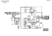
... FB503 FB402 DIG GND CL534 CL502 CL501 CL504 CL503 CL506 CL505 CL508 CL507 CL510 CL509 CL512 CL511 CN502 12P 1 M_G 2R 3 DCOUT 4B 5 YCGND 6C 7 VIDEO 8Y 9 AUR 10 VIGND 11 AUL 12 AUGND AV MULTI OUT Suffix of -51 RB502 75 1 2 3 4 5 6 7 8 0.8 (0.4) 0 (0.4) 0 (1.1) 0 (1.3) 1.7 0 2.2 4.9 2.2 R528... RDATA5 RDATA6 RDATA7 SCIN SYNCIN NT/PAL GDATA7 GDATA6 GDATA5 37 IC502 POWER_SAVE N. Reproduction Prohibited PU-23 (3/4) SCPH-9000 SERIES CN602 5P +8V 1 GND 2 +3.3V 3 GND 4 RESET 5 TO POWER BLOCK CL611 C620 0.001u B C601 47u 16V CL612 PS604 2A PS605 0.6A C631 0.01u B C643 1u...
... FB503 FB402 DIG GND CL534 CL502 CL501 CL504 CL503 CL506 CL505 CL508 CL507 CL510 CL509 CL512 CL511 CN502 12P 1 M_G 2R 3 DCOUT 4B 5 YCGND 6C 7 VIDEO 8Y 9 AUR 10 VIGND 11 AUL 12 AUGND AV MULTI OUT Suffix of -51 RB502 75 1 2 3 4 5 6 7 8 0.8 (0.4) 0 (0.4) 0 (1.1) 0 (1.3) 1.7 0 2.2 4.9 2.2 R528... RDATA5 RDATA6 RDATA7 SCIN SYNCIN NT/PAL GDATA7 GDATA6 GDATA5 37 IC502 POWER_SAVE N. Reproduction Prohibited PU-23 (3/4) SCPH-9000 SERIES CN602 5P +8V 1 GND 2 +3.3V 3 GND 4 RESET 5 TO POWER BLOCK CL611 C620 0.001u B C601 47u 16V CL612 PS604 2A PS605 0.6A C631 0.01u B C643 1u...
Service Manual
Page 13
...SD3 SD4 SD5 SD6 SD7 SD8 SD9 SD10 SD11 SD12 SD13 SD14 SD15 SCPH-9000 SERIES S301 R793 100k R712 3.3k R706 470k R705 100k C705 0.... CL 787 FB704 Suffix of -51 M SPINDLE MOTOR M SLED MOTOR MOT_+8V MOT GND C776 4.7u B 3216 IC722 FOCUS/TRACKING COIL DRIVE MOTOR DRIVE IC722 BA5S77FP-E2 IC310 DRAM IC310 MSM51260C-60JS MED0 MED1 MED3 MED5 MED8 MED10 MED12 MED14 MEA0 MEA1 MEA2 MEA3 2.4 (1.8) 2.1 (1.4) 1.6 ...+ 15 TRK- 16 FCS- C RAS WE N. C DECA4 DECA3 DECA2 DECA1 DECA0 VSS NDLY RESET DECD6 DECD7 N. C N. C N. C N. Reproduction Prohibited PU-23 (4/4) SER_+3.5V SER GND...
...SD3 SD4 SD5 SD6 SD7 SD8 SD9 SD10 SD11 SD12 SD13 SD14 SD15 SCPH-9000 SERIES S301 R793 100k R712 3.3k R706 470k R705 100k C705 0.... CL 787 FB704 Suffix of -51 M SPINDLE MOTOR M SLED MOTOR MOT_+8V MOT GND C776 4.7u B 3216 IC722 FOCUS/TRACKING COIL DRIVE MOTOR DRIVE IC722 BA5S77FP-E2 IC310 DRAM IC310 MSM51260C-60JS MED0 MED1 MED3 MED5 MED8 MED10 MED12 MED14 MEA0 MEA1 MEA2 MEA3 2.4 (1.8) 2.1 (1.4) 1.6 ...+ 15 TRK- 16 FCS- C RAS WE N. C DECA4 DECA3 DECA2 DECA1 DECA0 VSS NDLY RESET DECD6 DECD7 N. C N. C N. C N. Reproduction Prohibited PU-23 (4/4) SER_+3.5V SER GND...
Service Manual
Page 19
uPA . . : µPA . . uPC . . : µPC . . Part No. CONSOLE ASSEMBLE PARTS LIST S ! PP O S-FRONT O STOPPER O LOWER 1-954-377-31 1-959-132-13 3-052-152-02 3-052-440-02 3-056-223-01 O LOWER O SHIELD O L-...if requested. are critical for example : uA . . : µA . . SC Ref. Replace only with part number specified. Parts classification Parts are classified dy stock availabity in the diagrams or the components used on the set. • -XX and -X mean standardized parts, so they may have some difference from the original one. • RESISTORS METAL : Metal-film...
uPA . . : µPA . . uPC . . : µPC . . Part No. CONSOLE ASSEMBLE PARTS LIST S ! PP O S-FRONT O STOPPER O LOWER 1-954-377-31 1-959-132-13 3-052-152-02 3-052-440-02 3-056-223-01 O LOWER O SHIELD O L-...if requested. are critical for example : uA . . : µA . . SC Ref. Replace only with part number specified. Parts classification Parts are classified dy stock availabity in the diagrams or the components used on the set. • -XX and -X mean standardized parts, so they may have some difference from the original one. • RESISTORS METAL : Metal-film...

Service Manual
Page 23
...part number specified. Replace only with mark. ! AC O ! CORD, CONNECTION ADAPTOR, RF CONNECTOR, CONVERSION ANALOG CONTROLLER...CONTROLLER 1-783-928-15 O SHEET 3-961-986-01 O CUSHION 3-967-122-01 O CARTON 3-987-032-21 O CARTON 3-987-178-61 O CARTON O CARTON O CARTON O CARTON O CONSOLE 3-050-234-61 3-050-234-71 3-987-178-71 3-050-234-81 A-6788-646-A O CONSOLE O CONSOLE O CONSOLE A-6788-647-A A-6788-648-A A-6788-649-A Description CORD, POWER 2P CORD, POWER CORD, POWER CORD, AC POWER CORD, AC POWER CORD, POWER... PU23-51) (for safety. SCPH-9000 SERIES Remark (9000) (9001...
...part number specified. Replace only with mark. ! AC O ! CORD, CONNECTION ADAPTOR, RF CONNECTOR, CONVERSION ANALOG CONTROLLER...CONTROLLER 1-783-928-15 O SHEET 3-961-986-01 O CUSHION 3-967-122-01 O CARTON 3-987-032-21 O CARTON 3-987-178-61 O CARTON O CARTON O CARTON O CARTON O CONSOLE 3-050-234-61 3-050-234-71 3-987-178-71 3-050-234-81 A-6788-646-A O CONSOLE O CONSOLE O CONSOLE A-6788-647-A A-6788-648-A A-6788-649-A Description CORD, POWER 2P CORD, POWER CORD, POWER CORD, AC POWER CORD, AC POWER CORD, POWER... PU23-51) (for safety. SCPH-9000 SERIES Remark (9000) (9001...

Service Manual
Page 25
... R003 ! R118 ! R119 ! C008 ! D004 ! ZD001 ! ZD102 ! IC101 Part No. 1-468-365-11 Description Power Block FILM 0.1uF 275V ELECT 100uF 200V CERAMIC 220PF 1KV FILM 0.1uF 50V CERAMIC 1000PF... ! C001 ! C105 ! D001 ! L001 ! Q001 ! R009 ! R113 ! R117 ! Replace only with mark. ! C003 ! C013 ! CN101 ! D003 ! Description CHOKE COIL ELF15N004A CHOKE... 1K 1/4W CARBON 100 1/4W SWITCH ESB32101N SWITCH ESE20B6 SCPH-9000 SERIES Remark - 24 - C005 ! D006 ! ZD103 ! T001 ! C004 ! D009 ! or dotted line with part number specified. C102 ! D101 ! PD101 ! C110 ! D102...
... R003 ! R118 ! R119 ! C008 ! D004 ! ZD001 ! ZD102 ! IC101 Part No. 1-468-365-11 Description Power Block FILM 0.1uF 275V ELECT 100uF 200V CERAMIC 220PF 1KV FILM 0.1uF 50V CERAMIC 1000PF... ! C001 ! C105 ! D001 ! L001 ! Q001 ! R009 ! R113 ! R117 ! Replace only with mark. ! C003 ! C013 ! CN101 ! D003 ! Description CHOKE COIL ELF15N004A CHOKE... 1K 1/4W CARBON 100 1/4W SWITCH ESB32101N SWITCH ESE20B6 SCPH-9000 SERIES Remark - 24 - C005 ! D006 ! ZD103 ! T001 ! C004 ! D009 ! or dotted line with part number specified. C102 ! D101 ! PD101 ! C110 ! D102...

Service Manual
Page 28
... Remark SC Ref. Q002 ! Q101 ! R004 ! R011 ! R012 ! R110 ! SW101 ! are critical for safety. Replace only with mark. ! Q103 ! R108 ! or dotted line with part number specified. Q001 ! T001 ! R104 ! R115 ! SW102 Part No. Part No. Description - 27 - R006 ! R008 ! R112 ! SCPH-9000 SERIES Remark The components identified by mark ! PC001 ! R001 ! R013 ! R117 ! R107 ! Q104...
... Remark SC Ref. Q002 ! Q101 ! R004 ! R011 ! R012 ! R110 ! SW101 ! are critical for safety. Replace only with mark. ! Q103 ! R108 ! or dotted line with part number specified. Q001 ! T001 ! R104 ! R115 ! SW102 Part No. Part No. Description - 27 - R006 ! R008 ! R112 ! SCPH-9000 SERIES Remark The components identified by mark ! PC001 ! R001 ! R013 ! R117 ! R107 ! Q104...


