Owner's Manual
Page 5
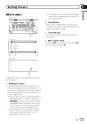
...position. 2 Terminal cover Remove the cover before connecting the amplifier. En 5 For details, refer to Before connecting the amplifier on page 7. 3 Power indicator The power indicator lights up to indicate power ON. 4 INPUT (input) switch Select 2CH for two-channel input and 1CH for speaker outputs A and B to match...is turned up , turn the gain control to lower level. English 23 2 Back side 4 To adjust the switch, use with an RCA equipped Pioneer car stereo, with an RCA equipped car stereo (standard output of the car stereo output. ! Setting the unit What's what Right side 1 Front...
...position. 2 Terminal cover Remove the cover before connecting the amplifier. En 5 For details, refer to Before connecting the amplifier on page 7. 3 Power indicator The power indicator lights up to indicate power ON. 4 INPUT (input) switch Select 2CH for two-channel input and 1CH for speaker outputs A and B to match...is turned up , turn the gain control to lower level. English 23 2 Back side 4 To adjust the switch, use with an RCA equipped Pioneer car stereo, with an RCA equipped car stereo (standard output of the car stereo output. ! Setting the unit What's what Right side 1 Front...
Owner's Manual
Page 8
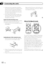
... for a 4 W load or a single 4 W speaker per channel. For any further enquiries, contact your local authorized Pioneer dealer or customer service. 8 En Install and route the separately sold battery wire, ground wire, speaker wires and the amplifier as far away as possible from the antenna, antenna cable and tuner... follow the speaker output connection diagram for bridging shown on rear: two 8 W speakers in parallel for a two-channel amplifier, with a 4 W load, either wire two 8 W speakers in parallel, Left + and Right * (Diagram A) or use a single 4 W speaker. Section 02 Connecting the ...
... for a 4 W load or a single 4 W speaker per channel. For any further enquiries, contact your local authorized Pioneer dealer or customer service. 8 En Install and route the separately sold battery wire, ground wire, speaker wires and the amplifier as far away as possible from the antenna, antenna cable and tuner... follow the speaker output connection diagram for bridging shown on rear: two 8 W speakers in parallel for a two-channel amplifier, with a 4 W load, either wire two 8 W speakers in parallel, Left + and Right * (Diagram A) or use a single 4 W speaker. Section 02 Connecting the ...
Owner's Manual
Page 10
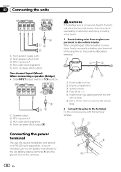
... the terminal screws. Connecting the power terminal The use of a special red battery and ground wire RD-223 (sold separately), is a risk of the amplifier to the positive (+) battery terminal. 1 Positive (+) terminal 2 Engine compartment 3 Vehicle interior 4 Fuse (30 A) × 2 5 Insert the O-... (input) switch to 1CH position. 2 3 14 1 Speaker output 2 RCA input jack A 3 RCA cable (sold separately) 5 From car stereo (RCA output) One-channel input (Mono) When connecting a speaker (Bridge) ! Section 02 Connecting the units 3 4 15 2 1 Front speaker output (Left) 2 Rear speaker output (Left) ...
... the terminal screws. Connecting the power terminal The use of a special red battery and ground wire RD-223 (sold separately), is a risk of the amplifier to the positive (+) battery terminal. 1 Positive (+) terminal 2 Engine compartment 3 Vehicle interior 4 Fuse (30 A) × 2 5 Insert the O-... (input) switch to 1CH position. 2 3 14 1 Speaker output 2 RCA input jack A 3 RCA cable (sold separately) 5 From car stereo (RCA output) One-channel input (Mono) When connecting a speaker (Bridge) ! Section 02 Connecting the units 3 4 15 2 1 Front speaker output (Left) 2 Rear speaker output (Left) ...
Owner's Manual
Page 14
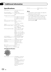
....8 V to 15.1 V allowable) Grounding system Negative type Current consumption 23 A (at continuous power, 4 W) Average current consumption 6.4 A (4 W for two channels) 4.1 A (4 W for one channel) 8 A (2 W for two channels) Fuse 30 A Dimensions (W × H × D) ... 255 mm × 50 mm × 104 mm (10 in. × 2 in....(at 14.4 V, 2 W and ≦ 1 % THD+N) 14 En The average current drawn is input. mum current drawn by multiple power amplifiers. Use this value when working out total current drawn by this unit when an audio signal is nearly the maxi- Power output 125 W RMS ×...
....8 V to 15.1 V allowable) Grounding system Negative type Current consumption 23 A (at continuous power, 4 W) Average current consumption 6.4 A (4 W for two channels) 4.1 A (4 W for one channel) 8 A (2 W for two channels) Fuse 30 A Dimensions (W × H × D) ... 255 mm × 50 mm × 104 mm (10 in. × 2 in....(at 14.4 V, 2 W and ≦ 1 % THD+N) 14 En The average current drawn is input. mum current drawn by multiple power amplifiers. Use this value when working out total current drawn by this unit when an audio signal is nearly the maxi- Power output 125 W RMS ×...


