
Owner's Manual
Page 3
...subwoofer. Connect the battery wire directly to the car battery positive terminal (+) and the ground wire to the car body. • Do not touch the amplifier with liquids due to terminals and wires. If both L (left) and R (right) channels are behind the panel when drilling a hole for future...replace the fuse with liquids. The use the special red battery and ground wire [RD-228], which is installed. Also, do not touch the amplifier when it down on the latest products and technologies. 3 Download owner's manuals, order product catalogues, research new products, and much more. Be...
...subwoofer. Connect the battery wire directly to the car battery positive terminal (+) and the ground wire to the car body. • Do not touch the amplifier with liquids due to terminals and wires. If both L (left) and R (right) channels are behind the panel when drilling a hole for future...replace the fuse with liquids. The use the special red battery and ground wire [RD-228], which is installed. Also, do not touch the amplifier when it down on the latest products and technologies. 3 Download owner's manuals, order product catalogues, research new products, and much more. Be...

Owner's Manual
Page 4
... screws with your car stereo, change the BFC switch using a small standard tip screwdriver. For instruction of connecting the bass boost remote control to the amplifier, see the "Connection Diagram" section. 3 BFC (Beat Frequency Control) Switch BFC switch is switched on the bottom of the unit. Power Indicator The power indicator...
... screws with your car stereo, change the BFC switch using a small standard tip screwdriver. For instruction of connecting the bass boost remote control to the amplifier, see the "Connection Diagram" section. 3 BFC (Beat Frequency Control) Switch BFC switch is switched on the bottom of the unit. Power Indicator The power indicator...
Owner's Manual
Page 5
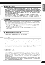
... the volume is turned up , turn gain control clockwise. Input Switch It is possible to input from MASTER, SYNC and SYNC INV. In this power amplifier is turned up , turn the gain control counter-clockwise. If the speaker impedance exceeds 2 Ω (4 Ω when using the speaker input terminals, turn... input wire with the ex. When using speakers with max. Set the MODE SELECT switch to the MASTER position when using with an RCA equipped Pioneer car stereo with synthetic impeadance 2 Ω to 8 Ω, slide the switch to the SYNC INV mode is too low, even when the ...
... the volume is turned up , turn gain control clockwise. Input Switch It is possible to input from MASTER, SYNC and SYNC INV. In this power amplifier is turned up , turn the gain control counter-clockwise. If the speaker impedance exceeds 2 Ω (4 Ω when using the speaker input terminals, turn... input wire with the ex. When using speakers with max. Set the MODE SELECT switch to the MASTER position when using with an RCA equipped Pioneer car stereo with synthetic impeadance 2 Ω to 8 Ω, slide the switch to the SYNC INV mode is too low, even when the ...
Owner's Manual
Page 6
... the gain control of the amplifier Normal gain Equal power Maximum gain Gain Control of This... V (Standard: 500 mV) Signal waveform Amplifier gain (normal) Signal waveform Amplifier gain (maximum) • With high output... of the amplifier to a proper position according to ... the gain of the amplifier the power changes only slightly...the amplifier and the output power of the ...Amplifier gain (normal) Head unit volume steps Amplifier gain (maximum) • If you decrease the volume of the head unit and set the gain control of the amplifier...raise the gain of the amplifier to an improper level, only...
... the gain control of the amplifier Normal gain Equal power Maximum gain Gain Control of This... V (Standard: 500 mV) Signal waveform Amplifier gain (normal) Signal waveform Amplifier gain (maximum) • With high output... of the amplifier to a proper position according to ... the gain of the amplifier the power changes only slightly...the amplifier and the output power of the ...Amplifier gain (normal) Head unit volume steps Amplifier gain (maximum) • If you decrease the volume of the head unit and set the gain control of the amplifier...raise the gain of the amplifier to an improper level, only...
Owner's Manual
Page 7
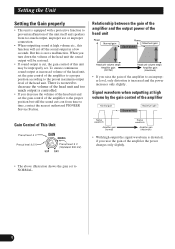
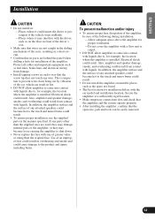
...Do not ground the speaker wire directly or connect a negative (-) lead wire for vehicles with a 12-volt battery and negative grounding. Amplifier damage, smoke, and overheating could result in the "Connecting the Unit" section. ENGLISH ESPAÑOL DEUTSCH FRANÇAIS ITALIANO ...NEDERLANDS Connecting the Unit CAUTION • Disconnect the negative (-) terminal of the battery to avoid the risk of short-circuit and damage to the amplifier; 1: a subwoofer with a 420 W or larger nominal input and an impedance 4 Ω, 2: a subwoofer with a 600 W or larger nominal input and an...
...Do not ground the speaker wire directly or connect a negative (-) lead wire for vehicles with a 12-volt battery and negative grounding. Amplifier damage, smoke, and overheating could result in the "Connecting the Unit" section. ENGLISH ESPAÑOL DEUTSCH FRANÇAIS ITALIANO ...NEDERLANDS Connecting the Unit CAUTION • Disconnect the negative (-) terminal of the battery to avoid the risk of short-circuit and damage to the amplifier; 1: a subwoofer with a 420 W or larger nominal input and an impedance 4 Ω, 2: a subwoofer with a 600 W or larger nominal input and an...
Owner's Manual
Page 8
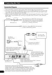
...to the left (RCA). • In the case of the car stereo (SYSTEM REMOTE CONTROL). This is because the LPF of the amplifier cannot be used for the bass boost remote control Connect this wire to the system remote control terminal of connecting the external output from a ... the Unit" section. Jack for full- System remote control wire (sold separately) After making all other connections at the amplifier, connect the battery wire terminal of the amplifier to the positive (+) terminal of this jack and the bass boost remote control with RCA pin plugs (sold separately) Connect...
...to the left (RCA). • In the case of the car stereo (SYSTEM REMOTE CONTROL). This is because the LPF of the amplifier cannot be used for the bass boost remote control Connect this wire to the system remote control terminal of connecting the external output from a ... the Unit" section. Jack for full- System remote control wire (sold separately) After making all other connections at the amplifier, connect the battery wire terminal of the amplifier to the positive (+) terminal of this jack and the bass boost remote control with RCA pin plugs (sold separately) Connect...
Owner's Manual
Page 9
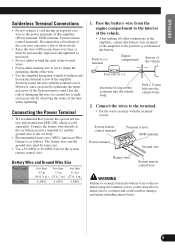
...bind the ends of the twisted wires. • Fasten while making all other connections to the amplifier, connect the battery wire terminal of the amplifier to the power terminals of this amplifier (Power terminal, GND terminal, System remote control terminal). Pass the battery wire from the engine compartment...Connect the battery wire directly to the car battery positive terminal (+) and the ground wire to tighten and loosen the terminal screw of the amplifier. Securely fasten the wire with the terminal screws. Drill a 13 mm hole into the vehicle body. ENGLISH ESPAÑOL DEUTSCH FRAN...
...bind the ends of the twisted wires. • Fasten while making all other connections to the amplifier, connect the battery wire terminal of the amplifier to the power terminals of this amplifier (Power terminal, GND terminal, System remote control terminal). Pass the battery wire from the engine compartment...Connect the battery wire directly to the car battery positive terminal (+) and the ground wire to tighten and loosen the terminal screw of the amplifier. Securely fasten the wire with the terminal screws. Drill a 13 mm hole into the vehicle body. ENGLISH ESPAÑOL DEUTSCH FRAN...

Owner's Manual
Page 10
... terminals. • Fix the speaker wires securely with RCA pin cord To RCA input jack of this case. • In the case the amplifier and head unit are connected using a speaker input wire with the system remote control wire. It is being used. Terminal screws Speaker output terminal ...turned on . Connecting the Unit Connecting the Speaker Output Terminals • Use a 10 AWG to 12 mm (1/2inch) 2. Expose the end of the amplifier is not to connect the system remote control wire in this unit. Note: • Connect the system remote control wire when the power of the...
... terminals. • Fix the speaker wires securely with RCA pin cord To RCA input jack of this case. • In the case the amplifier and head unit are connected using a speaker input wire with the system remote control wire. It is being used. Terminal screws Speaker output terminal ...turned on . Connecting the Unit Connecting the Speaker Output Terminals • Use a 10 AWG to 12 mm (1/2inch) 2. Expose the end of the amplifier is not to connect the system remote control wire in this unit. Note: • Connect the system remote control wire when the power of the...

Owner's Manual
Page 11
... 4 Ω Speaker 2 Ω Speaker 2 Ω Speaker 2 Ω Bridged Mode 1 Ω Bridged Mode Do NOT install or use this amplifier by wiring speakers rated at 2 Ω (or lower) in combination, set the gain control, subsonic select switch, cut off frequency control for LPF and... been set to achieve a 1 Ω (or lower) bridged mode (Diagram B). To properly install or use these amplifiers with other amplifiers. • When synchronously connecting two or more amplifiers in combination, only use a bridged mode and achieve a 2 Ω load, wire two 4 Ω speakers in...
... 4 Ω Speaker 2 Ω Speaker 2 Ω Speaker 2 Ω Bridged Mode 1 Ω Bridged Mode Do NOT install or use this amplifier by wiring speakers rated at 2 Ω (or lower) in combination, set the gain control, subsonic select switch, cut off frequency control for LPF and... been set to achieve a 1 Ω (or lower) bridged mode (Diagram B). To properly install or use these amplifiers with other amplifiers. • When synchronously connecting two or more amplifiers in combination, only use a bridged mode and achieve a 2 Ω load, wire two 4 Ω speakers in...
Owner's Manual
Page 12
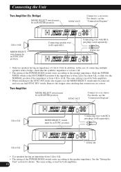
... plugs (sold separately). For details, see the "Connection Diagram". 1 Ω to 16 Ω. See the "Setting the Unit" section for both amplifiers. • When switching to 16 Ω MODE SELECT switch must be in SYNC INV position. Connecting speaker wire (sold separately). 1 Ω to... the speaker impedance. Two Amplifier MODE SELECT switch must be in the case of 2 Ω to 8 Ω MODE SELECT switch must be in MASTER position. SYNC OUT ...
... plugs (sold separately). For details, see the "Connection Diagram". 1 Ω to 16 Ω. See the "Setting the Unit" section for both amplifiers. • When switching to 16 Ω MODE SELECT switch must be in SYNC INV position. Connecting speaker wire (sold separately). 1 Ω to... the speaker impedance. Two Amplifier MODE SELECT switch must be in the case of 2 Ω to 8 Ω MODE SELECT switch must be in MASTER position. SYNC OUT ...
Owner's Manual
Page 13
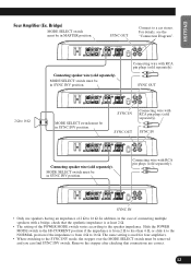
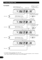
ENGLISH ESPAÑOL DEUTSCH FRANÇAIS ITALIANO NEDERLANDS Four Amplifier (Ex. Connecting wire with RCA pin plugs (sold separately). Bridge) MODE SELECT switch must be in SYNC INV position. For details, see the "Connection Diagram". ... IN • Only use speakers having an impedance of the POWER MODE switch varies according to 16 Ω. The same setting is used for four amplifiers. • When switching to a car stereo. Remove the stopper after checking that the synthetic impedance is from 2 Ω to less than 4 Ω, or slide it...
ENGLISH ESPAÑOL DEUTSCH FRANÇAIS ITALIANO NEDERLANDS Four Amplifier (Ex. Connecting wire with RCA pin plugs (sold separately). Bridge) MODE SELECT switch must be in SYNC INV position. For details, see the "Connection Diagram". ... IN • Only use speakers having an impedance of the POWER MODE switch varies according to 16 Ω. The same setting is used for four amplifiers. • When switching to a car stereo. Remove the stopper after checking that the synthetic impedance is from 2 Ω to less than 4 Ω, or slide it...
Owner's Manual
Page 14
...of the POWER MODE switch varies according to a car stereo. The same setting is used for details. Connecting the Unit Four Amplifier MODE SELECT switch must be in SYNC position. Connecting wire with RCA pin plugs (sold separately). SYNC OUT Connect to the speaker... impedance. See the "Setting the Unit" section for four amplifiers. 13 SYNC OUT MODE SELECT switch must be in SYNC position. For details, see the "Connection Diagram". 1 Ω to 8 Ω 1...
...of the POWER MODE switch varies according to a car stereo. The same setting is used for details. Connecting the Unit Four Amplifier MODE SELECT switch must be in SYNC position. Connecting wire with RCA pin plugs (sold separately). SYNC OUT Connect to the speaker... impedance. See the "Setting the Unit" section for four amplifiers. 13 SYNC OUT MODE SELECT switch must be in SYNC position. For details, see the "Connection Diagram". 1 Ω to 8 Ω 1...
Owner's Manual
Page 15
... sliding mechanism of the seats, resulting in a short-circuit. • Confirm that no parts are used, they may damage internal parts of the amplifier, or they may interfere with the driver, such as on unstable places such as fuel lines, brake lines and electrical wiring from being cut by... with one of greater value or rating than the supplied ones are behind the panel when drilling a hole for example, the location where the amplifier is installed. If any attached speakers could become hot to the touch and minor burns could cause damage to , for installation differs with liquids ...
... sliding mechanism of the seats, resulting in a short-circuit. • Confirm that no parts are used, they may damage internal parts of the amplifier, or they may interfere with the driver, such as on unstable places such as fuel lines, brake lines and electrical wiring from being cut by... with one of greater value or rating than the supplied ones are behind the panel when drilling a hole for example, the location where the amplifier is installed. If any attached speakers could become hot to the touch and minor burns could cause damage to , for installation differs with liquids ...
Owner's Manual
Page 16
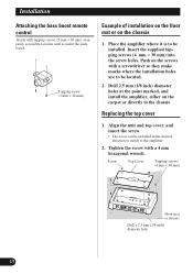
... direction to match to the chassis. Insert the supplied tapping screws (4 mm × 30 mm) into the screw holes. Replacing the top cover 1. Place the amplifier where it is to be installed. Push on the chassis 1. Tighten the screw with tapping screws (3 mm × 10 mm) at the point marked, and...
... direction to match to the chassis. Insert the supplied tapping screws (4 mm × 30 mm) into the screw holes. Replacing the top cover 1. Place the amplifier where it is to be installed. Push on the chassis 1. Tighten the screw with tapping screws (3 mm × 10 mm) at the point marked, and...

Owner's Manual
Page 17
Use this value when working out total current drawn by this unit when an audio signal is nearly the maximum current drawn by multiple power amplifiers. 16 ENGLISH ESPAÑOL DEUTSCH FRANÇAIS ITALIANO NEDERLANDS Specifications Power source ...14.4 V DC (10.8 V to 15.1 V allowable) Grounding system ...Negative type Current ...
Use this value when working out total current drawn by this unit when an audio signal is nearly the maximum current drawn by multiple power amplifiers. 16 ENGLISH ESPAÑOL DEUTSCH FRANÇAIS ITALIANO NEDERLANDS Specifications Power source ...14.4 V DC (10.8 V to 15.1 V allowable) Grounding system ...Negative type Current ...

