Service Manual
Page 1
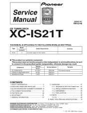
... DISASSEMBLY 60 7.1.4 PCB LOCATION 64 7.2 PARTS 65 7.2.1 IC 65 8. Box 1760, Long Beach, CA 90801-1760, U.S.A. PIONEER ELECTRONIC (EUROPE) N.V. Type Model XC-IS21T Power Requirement Remarks ZUCXJ O DC power supply from other system This product is a system(s) component. EXPLODED VIEWS AND PARTS...may result. P.O. CD TUNER DECK XC-IS21T ORDER NO. This product does not function properly when independent; SAFETY INFORMATION 2 2. Component System IS-21T Service Manual Remarks CD TUNER DECK STEREO POWER AMPLIFIER SPEAKER SYSTEM XC-IS21T M-IS21 S-IS21 RRV2148 RRV2143 ...
... DISASSEMBLY 60 7.1.4 PCB LOCATION 64 7.2 PARTS 65 7.2.1 IC 65 8. Box 1760, Long Beach, CA 90801-1760, U.S.A. PIONEER ELECTRONIC (EUROPE) N.V. Type Model XC-IS21T Power Requirement Remarks ZUCXJ O DC power supply from other system This product is a system(s) component. EXPLODED VIEWS AND PARTS...may result. P.O. CD TUNER DECK XC-IS21T ORDER NO. This product does not function properly when independent; SAFETY INFORMATION 2 2. Component System IS-21T Service Manual Remarks CD TUNER DECK STEREO POWER AMPLIFIER SPEAKER SYSTEM XC-IS21T M-IS21 S-IS21 RRV2148 RRV2143 ...
Service Manual
Page 3
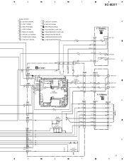
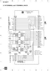
TERMINAL ASSY H C CN31 CN131 CN7101 V+12UN 9 V+12UN 9 1 V+12UN TO. STEREO PWER AMPLIFIER (M-IS21) AC 8 AC 8 3 AC V+5.6V 7 V+5UN 10 B2GND 3 V+5.6V 7 V+5UN 10 B2GND 3 4 V+5.6V 5 V+5UN 6 B2GND B1GND 2 B1GND 2 9 B1GND CN5 18 V+12TX 8 GNDU 16 ... V IN 8 VCC 9 GND OPT 7 (D.O) 12 3 OPT OUT LIN2 2 (L2) LINE IN2 CN3 8 9 7 (LO2) 1 LOUT2 1 (LO2) LINE OUT2 B LOUT2 OPT IN/OUT V+5 OPT GND OPT CN1 D. 5 6 7 8 XC-IS21T SIGNAL ROUTE (CD) : CD AUDIO SIGNAL (L1) : LINE 1 SIGNAL (PB) : DECK PB SIGNAL (L2) : LINE 2 SIGNAL (MO) : MAIN OUT SIGNAL (D.O) : OPTICAL OUT SIGNAL (TX...
TERMINAL ASSY H C CN31 CN131 CN7101 V+12UN 9 V+12UN 9 1 V+12UN TO. STEREO PWER AMPLIFIER (M-IS21) AC 8 AC 8 3 AC V+5.6V 7 V+5UN 10 B2GND 3 V+5.6V 7 V+5UN 10 B2GND 3 4 V+5.6V 5 V+5UN 6 B2GND B1GND 2 B1GND 2 9 B1GND CN5 18 V+12TX 8 GNDU 16 ... V IN 8 VCC 9 GND OPT 7 (D.O) 12 3 OPT OUT LIN2 2 (L2) LINE IN2 CN3 8 9 7 (LO2) 1 LOUT2 1 (LO2) LINE OUT2 B LOUT2 OPT IN/OUT V+5 OPT GND OPT CN1 D. 5 6 7 8 XC-IS21T SIGNAL ROUTE (CD) : CD AUDIO SIGNAL (L1) : LINE 1 SIGNAL (PB) : DECK PB SIGNAL (L2) : LINE 2 SIGNAL (MO) : MAIN OUT SIGNAL (D.O) : OPTICAL OUT SIGNAL (TX...
Service Manual
Page 5
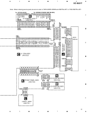
STEREO POWER AMP (M-IS21) CN7102 CN7101 H A R-TERMINAL ASSY CN132 (AWU7315) CN131 CN2 J2201 CN32 CN31 CN2603 CN150 CN50 CN20 J2202 DECK ASSY (AWU7334) CN5 CN105 C U- OPTION DECK To. COM ASSY (AWU7327) CN2701 B J CN2301 CN2302 K FRONT PANEL ASSY (AWU7308) CN51 J155 N CD CLOSE SW ASSY J55 (AWU7320) J154 M CD OPEN SW ASSY J54 (AWU7319) J51 L LIGHT-L ASSY (AWU7321) 5 6 7 C D 19 8 5 6 7 8 XC-IS21T Note : When ordering service parts, be sure to refer to "EXPLODED VIEWS and PARTS LIST" or "PCB PARTS LIST". To.
STEREO POWER AMP (M-IS21) CN7102 CN7101 H A R-TERMINAL ASSY CN132 (AWU7315) CN131 CN2 J2201 CN32 CN31 CN2603 CN150 CN50 CN20 J2202 DECK ASSY (AWU7334) CN5 CN105 C U- OPTION DECK To. COM ASSY (AWU7327) CN2701 B J CN2301 CN2302 K FRONT PANEL ASSY (AWU7308) CN51 J155 N CD CLOSE SW ASSY J55 (AWU7320) J154 M CD OPEN SW ASSY J54 (AWU7319) J51 L LIGHT-L ASSY (AWU7321) 5 6 7 C D 19 8 5 6 7 8 XC-IS21T Note : When ordering service parts, be sure to refer to "EXPLODED VIEWS and PARTS LIST" or "PCB PARTS LIST". To.
Service Manual
Page 14
OPTION DECK D H 28 1 2 3 4 STEREO POWER AMPLIFIER (M-IS21) E CN31 B VTL1096 (L1) VTL1096 (L1) (LO1) VTL1096 VTL1096 (MO) (LO1) (L1) E CN32 C VTL1096 VTL1096 (MO) (MO) CN132 CN7102 VTL1096 SIGNAL ROUTE (MO) : MAIN OUT SIGNAL (L1) : LINE 1 SIGNAL (LO1) : LINE OUT1 SIGNAL To. 1 2 3 XC-IS21T 3.7 R-TERMINAL and F-TERMINAL ASSYS A H R- TERMINAL ASSY (AWU7315) CN7101 4 CN131 TO.
OPTION DECK D H 28 1 2 3 4 STEREO POWER AMPLIFIER (M-IS21) E CN31 B VTL1096 (L1) VTL1096 (L1) (LO1) VTL1096 VTL1096 (MO) (LO1) (L1) E CN32 C VTL1096 VTL1096 (MO) (MO) CN132 CN7102 VTL1096 SIGNAL ROUTE (MO) : MAIN OUT SIGNAL (L1) : LINE 1 SIGNAL (LO1) : LINE OUT1 SIGNAL To. 1 2 3 XC-IS21T 3.7 R-TERMINAL and F-TERMINAL ASSYS A H R- TERMINAL ASSY (AWU7315) CN7101 4 CN131 TO.
Service Manual
Page 21
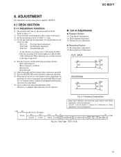
XC-IS21T 6. Use the labeled (A) side of Adjustments ¶ Playback Section (1) Tape Speed Confirmation (2) Head Azimuth Adjustment (3) Playback Level Adjustment ¶ Recording Section (1) Recording Bias Adjustment (2) .... (Refer to Fig. 6-3). (2) Clean the heads and demagnetize them using a head eraser. (3) Set the measurement level to 5 minutes before adjustment. ADJUSTMENT For adjustment, use the stereo power amplifier (M-IS21). 6.1 DECK SECTION 6.1.1 Adjustment Condition (1) The ground at the time of adjustment shall be achieved. 7 List of the test tape. "DOLBY" and the...
XC-IS21T 6. Use the labeled (A) side of Adjustments ¶ Playback Section (1) Tape Speed Confirmation (2) Head Azimuth Adjustment (3) Playback Level Adjustment ¶ Recording Section (1) Recording Bias Adjustment (2) .... (Refer to Fig. 6-3). (2) Clean the heads and demagnetize them using a head eraser. (3) Set the measurement level to 5 minutes before adjustment. ADJUSTMENT For adjustment, use the stereo power amplifier (M-IS21). 6.1 DECK SECTION 6.1.1 Adjustment Condition (1) The ground at the time of adjustment shall be achieved. 7 List of the test tape. "DOLBY" and the...

