Service Manual
Page 1
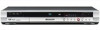
... this to the customer. (*) : Initial Setup (Clock Setting, Remote Control Set, Channel settings, Video Out settings, Audio In settings, Audio Out settings, Language settings) Refer to the chapter 12 of the Operating Instructions for good services" . STANDBY/ON DISC HISTORY DISC NAVIGATOR PULL-OPEN VIDEO/R/RW OPEN/CLOSE REC REC MODE DVR-220-S DVD RECORDER DVR-220-S DVR-225-S ORDER NO. Model Type Power Requirement Region No. P.O. PIONEER EUROPE NV Haven 1087, Keetberglaan 1, 9120 Melsele, Belgium PIONEER ELECTRONICS ASIACENTRE PTE. RRV2925 THIS MANUAL IS APPLICABLE TO THE...
... this to the customer. (*) : Initial Setup (Clock Setting, Remote Control Set, Channel settings, Video Out settings, Audio In settings, Audio Out settings, Language settings) Refer to the chapter 12 of the Operating Instructions for good services" . STANDBY/ON DISC HISTORY DISC NAVIGATOR PULL-OPEN VIDEO/R/RW OPEN/CLOSE REC REC MODE DVR-220-S DVD RECORDER DVR-220-S DVR-225-S ORDER NO. Model Type Power Requirement Region No. P.O. PIONEER EUROPE NV Haven 1087, Keetberglaan 1, 9120 Melsele, Belgium PIONEER ELECTRONICS ASIACENTRE PTE. RRV2925 THIS MANUAL IS APPLICABLE TO THE...
Service Manual
Page 2
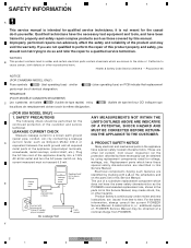
... TO THE CUSTOMER. 2. Plug the AC line cord of the appliance directly into a 120V AC 60 Hz outlet and turn the AC power switch on PCB indicate that replacement REMARQUE (POUR MODÈ...PIONEER Service Manual. F 2 DVR-220-S 1 2 3 4 WARNING B This product contains lead in this Service Manual. A subscription to time. These are known to the state of California to perform the repair of this manual. Improperly performed repairs can be obtained at a nominal charge from time to , or additional copies of the product and may be obtained by connecting...
... TO THE CUSTOMER. 2. Plug the AC line cord of the appliance directly into a 120V AC 60 Hz outlet and turn the AC power switch on PCB indicate that replacement REMARQUE (POUR MODÈ...PIONEER Service Manual. F 2 DVR-220-S 1 2 3 4 WARNING B This product contains lead in this Service Manual. A subscription to time. These are known to the state of California to perform the repair of this manual. Improperly performed repairs can be obtained at a nominal charge from time to , or additional copies of the product and may be obtained by connecting...
Service Manual
Page 4
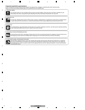
... damages or failures that adjustments, settings or cleaning should be made securely. C D E F 4 DVR-220-S 1 2 3 4 In accordance with this manual, if necessary. 5. Lubricants, glues, and replacement parts Appropriately applying grease or glue can maintain the product performances. By following the safety instructions described in this manual. 2. When you find the procedures bearing any of the product, optimum adjustments or specification confirmation is indispensable. But...
... damages or failures that adjustments, settings or cleaning should be made securely. C D E F 4 DVR-220-S 1 2 3 4 In accordance with this manual, if necessary. 5. Lubricants, glues, and replacement parts Appropriately applying grease or glue can maintain the product performances. By following the safety instructions described in this manual. 2. When you find the procedures bearing any of the product, optimum adjustments or specification confirmation is indispensable. But...

Service Manual
Page 5
...11 POWER SUPPLY UNIT ...40 3.12 WAVE FORMS...41 4. GENERAL INFORMATION ...66 7.1 DIAGNOSIS...66 7.1.1 CPRM ID NUMBER AND DATA SETTING 67 7.1.2 MODEL SETTING ...69 7.1.3 DOWNLOAD...70 7.1.4 SERVICE MODE ...72 7.1.5 ERROR RATE MEASUREMENT...83 D 7.1.6 VIDEO ADJUSTMENT FOR SPECIFIC AREA 85 7.1.8 SETUP SEQUENCE...90 7.1.9 DISASSEMBLY...91 7.2 IC ...95 7.3 OUTLINE OF THE PRODUCT ...112 7.4 DISC/CONTENT FORMAT ...115 7.5 CLEANING ...116 8. PANEL FACILITIES ...117 E F DVR-220-S 5 5 6 7 8 5 6 7 8 CONTENTS SAFETY INFORMATION...2 1. PCB CONNECTION DIAGRAM ...43...
...11 POWER SUPPLY UNIT ...40 3.12 WAVE FORMS...41 4. GENERAL INFORMATION ...66 7.1 DIAGNOSIS...66 7.1.1 CPRM ID NUMBER AND DATA SETTING 67 7.1.2 MODEL SETTING ...69 7.1.3 DOWNLOAD...70 7.1.4 SERVICE MODE ...72 7.1.5 ERROR RATE MEASUREMENT...83 D 7.1.6 VIDEO ADJUSTMENT FOR SPECIFIC AREA 85 7.1.8 SETUP SEQUENCE...90 7.1.9 DISASSEMBLY...91 7.2 IC ...95 7.3 OUTLINE OF THE PRODUCT ...112 7.4 DISC/CONTENT FORMAT ...115 7.5 CLEANING ...116 8. PANEL FACILITIES ...117 E F DVR-220-S 5 5 6 7 8 5 6 7 8 CONTENTS SAFETY INFORMATION...2 1. PCB CONNECTION DIAGRAM ...43...
Service Manual
Page 6
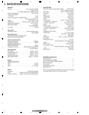
... Control input Mini jack Supplied accessories Remote control 1 Dry cell batteries (AA/R6P 2 Audio / Video cable (red/white/yellow 1 RF antenna cable 1 Power cable 1 Operating Instructions 1 Warranty card 1 Note: The specifications and design of this product are subject to change without notice, due to 85% (no condensation) TV format NTSC B Recording Recording format DVD Video Recording DVD-VIDEO Recordable discs DVD-RW (DVD Re-recordable disc) DVD-R (DVD Recordable disc) Video recording format Sampling frequency 13.5MHz Compression format MPEG Audio recording format...
... Control input Mini jack Supplied accessories Remote control 1 Dry cell batteries (AA/R6P 2 Audio / Video cable (red/white/yellow 1 RF antenna cable 1 Power cable 1 Operating Instructions 1 Warranty card 1 Note: The specifications and design of this product are subject to change without notice, due to 85% (no condensation) TV format NTSC B Recording Recording format DVD Video Recording DVD-VIDEO Recordable discs DVD-RW (DVD Re-recordable disc) DVD-R (DVD Recordable disc) Video recording format Sampling frequency 13.5MHz Compression format MPEG Audio recording format...
Service Manual
Page 67
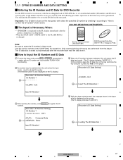
... data disc is swept out automatically after the power is turned on the player. [Recorder's ID Data Setting] C [Recorder's ID Number Setting] ID Number ? 2 Exit Exit 4 Insert The ID Data Disc ! If the number and data are not set on the ID label on the screen. (The FL display indicates "LOAD ID.") [Recorder's ID Data Setting] E 5 Loading The ID Data Disc ! Note: Service Remote Control Unit (GGF1381) DVD Recorder Data Disc B (GGV1179) (*) Refer to enter the ID number in Stop mode. Compare Mode 3 Enter Input...
... data disc is swept out automatically after the power is turned on the player. [Recorder's ID Data Setting] C [Recorder's ID Number Setting] ID Number ? 2 Exit Exit 4 Insert The ID Data Disc ! If the number and data are not set on the ID label on the screen. (The FL display indicates "LOAD ID.") [Recorder's ID Data Setting] E 5 Loading The ID Data Disc ! Note: Service Remote Control Unit (GGF1381) DVD Recorder Data Disc B (GGV1179) (*) Refer to enter the ID number in Stop mode. Compare Mode 3 Enter Input...
Service Manual
Page 69
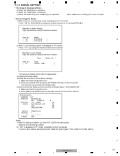
... panel. F DVR-220-S 69 5 6 7 8 Model [ 29 : DVR-220-S ] B [ 26 : DVR-225-S ] 2) After 1), the following screen is pressed. Press and hold [STOP] and press [STANDBY/ON] key on . 2. Make sure that the recorder is on TV when unsuitable number is displayed on TV monitor. A • How to all settings reset. 5) Enter the Service Mode and then confirm the Model Name " DVR-220/KU/CA ". 1. Input No. The recorder turns off with all its factory settings. 1. 5 6 7 8 7.1.2 MODEL SETTING • The Setup...
... panel. F DVR-220-S 69 5 6 7 8 Model [ 29 : DVR-220-S ] B [ 26 : DVR-225-S ] 2) After 1), the following screen is pressed. Press and hold [STOP] and press [STANDBY/ON] key on . 2. Make sure that the recorder is on TV when unsuitable number is displayed on TV monitor. A • How to all settings reset. 5) Enter the Service Mode and then confirm the Model Name " DVR-220/KU/CA ". 1. Input No. The recorder turns off with all its factory settings. 1. 5 6 7 8 7.1.2 MODEL SETTING • The Setup...

Service Manual
Page 70
... SYSCON program: The SYSCON program will not function properly if the power to " DOWNLOAD-1 " - 1 2 3 4 7.1.3 DOWNLOAD • The Download is Necessary When : a) After model setting b) When "NG" is displayed at First screen (version information, etc) A [Notes] Be sure NOT to turn unit off) 1) Open a disc tray in the " DVD " function. 2) Put the download disc on the tray. 3) Press and hold a " ESC ", then press " DISP " on FL changes to " DOWNLOAD-3 " (*) - However, the following data is deleted...
... SYSCON program: The SYSCON program will not function properly if the power to " DOWNLOAD-1 " - 1 2 3 4 7.1.3 DOWNLOAD • The Download is Necessary When : a) After model setting b) When "NG" is displayed at First screen (version information, etc) A [Notes] Be sure NOT to turn unit off) 1) Open a disc tray in the " DVD " function. 2) Put the download disc on the tray. 3) Press and hold a " ESC ", then press " DISP " on FL changes to " DOWNLOAD-3 " (*) - However, the following data is deleted...

Service Manual
Page 71
... updating the firmware. DVR-220-S 5 6 7 E F 71 8 5 6 7 2. Serial DOWNLOAD METHOD [Notes] This method is secondary way when the disc loading is appeared on and start the " UFU.exe ". . 3) Select the Firmware file. ("sz0" file) 4) Turn the DVD recorder on the screen. 8 A B C D . 5) Select the Communication Speed (Baud Rate) a) Base Speed 38,400 b) Data Send Speed 115,200 6) START * Even if you click "START" button, sometimes "Communication Error" may come out one to Download 1) Connect...
... updating the firmware. DVR-220-S 5 6 7 E F 71 8 5 6 7 2. Serial DOWNLOAD METHOD [Notes] This method is secondary way when the disc loading is appeared on and start the " UFU.exe ". . 3) Select the Firmware file. ("sz0" file) 4) Turn the DVD recorder on the screen. 8 A B C D . 5) Select the Communication Speed (Baud Rate) a) Base Speed 38,400 b) Data Send Speed 115,200 6) START * Even if you click "START" button, sometimes "Communication Error" may come out one to Download 1) Connect...
Service Manual
Page 81
... extension file is displayed "RecErr on a disc, or a problem of an error in to Lead-out C D E F DVR-220-S 81 5 6 7 8 Abbreviations: ECC = 4 byte Code for Error Correction UDF = Universal Disc Format PCA = Power Calibration Area OPC = Optical Power Control NWA = Next Writable Address VMG = Video Manager RMA = Recording Management Area MKB = Media Key Block TMP_VMGI = Temporary Video Manager Information Border = from Lead-in the drive system, scratches or dirt on the Subscreen 1 of the fourth screen. •...
... extension file is displayed "RecErr on a disc, or a problem of an error in to Lead-out C D E F DVR-220-S 81 5 6 7 8 Abbreviations: ECC = 4 byte Code for Error Correction UDF = Universal Disc Format PCA = Power Calibration Area OPC = Optical Power Control NWA = Next Writable Address VMG = Video Manager RMA = Recording Management Area MKB = Media Key Block TMP_VMGI = Temporary Video Manager Information Border = from Lead-in the drive system, scratches or dirt on the Subscreen 1 of the fourth screen. •...
Service Manual
Page 85
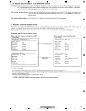
... not displayed as hyphens, those settings have been specifically set in a picture received by the tuner can be used. A How to enter setting modes: To enter General Setting mode, press the ESC key then the CHP/TIM key of General Setting mode. • The channels to the default settings or those of the remote control unit for service. 5 6 7 8 7.1.6 VIDEO ADJUSTMENT FOR SPECIFIC AREA Purposes: Depending on the area, jitter may appear in specific channel settings) E F DVR-220-S 85 5 6 7 8 For channels that...
... not displayed as hyphens, those settings have been specifically set in a picture received by the tuner can be used. A How to enter setting modes: To enter General Setting mode, press the ESC key then the CHP/TIM key of General Setting mode. • The channels to the default settings or those of the remote control unit for service. 5 6 7 8 7.1.6 VIDEO ADJUSTMENT FOR SPECIFIC AREA Purposes: Depending on the area, jitter may appear in specific channel settings) E F DVR-220-S 85 5 6 7 8 For channels that...

Service Manual
Page 86
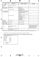
...Table 2: Key operations in Specific Channel Setting mode (effective only during recording/playback stop) Key A DIG/ANA Operation Switches cyclically between General Setting mode and Specific Channel Setting mode. Setting (∗: Default) - INPUT SELECT, CHANNEL +/- All channels assigned to have specific PLAY settings are canceled, and the specific settings are reset to the initial values. default values. Pressing the key resets the settings of General Setting mode are reset to keys on the remote control unit supplied with no display of General Setting mode are not affected...
...Table 2: Key operations in Specific Channel Setting mode (effective only during recording/playback stop) Key A DIG/ANA Operation Switches cyclically between General Setting mode and Specific Channel Setting mode. Setting (∗: Default) - INPUT SELECT, CHANNEL +/- All channels assigned to have specific PLAY settings are canceled, and the specific settings are reset to the initial values. default values. Pressing the key resets the settings of General Setting mode are reset to keys on the remote control unit supplied with no display of General Setting mode are not affected...
Service Manual
Page 88
... to the setting of Specific Channel Setting mode are not affected (they are retained). Normal (∗) /Short/Long - [SCAN Fwd] [Rev STILL STEP], Sets Std Det. ESC Exits AVIO setting for service. ON (∗) / OFF - [Rev ×3], [×3 Fwd] Sets Threshold level. (∗) Normal Auto Threshold Level Manual Threshold Level - F 88 DVR-220-S 1 2 3 4 1 2 3 4 Table 1: Key operations in General Setting mode when the channel currently displayed has specific settings] AVIO Specific Area Mode Ver*.** Input - [tuner ] Sync...
... to the setting of Specific Channel Setting mode are not affected (they are retained). Normal (∗) /Short/Long - [SCAN Fwd] [Rev STILL STEP], Sets Std Det. ESC Exits AVIO setting for service. ON (∗) / OFF - [Rev ×3], [×3 Fwd] Sets Threshold level. (∗) Normal Auto Threshold Level Manual Threshold Level - F 88 DVR-220-S 1 2 3 4 1 2 3 4 Table 1: Key operations in General Setting mode when the channel currently displayed has specific settings] AVIO Specific Area Mode Ver*.** Input - [tuner ] Sync...

Service Manual
Page 89
... aging operation stops. display, as an OSD. After disc detection, press the ESC key then the the REP.B key on the remote control unit for servicing to normal dislay. During Aging mode, the following operations are repeated in During Aging mode, the following operations are repeated in the order shown below . 1 The tray opens. 1 The tray opens. 2 The tray closes. 2 The tray closes. 3 Initialization 3 Recording for 1 minute 4 Recording for 60 minutes 4 Recording pause for 6 minutes 5 Playback...
... aging operation stops. display, as an OSD. After disc detection, press the ESC key then the the REP.B key on the remote control unit for servicing to normal dislay. During Aging mode, the following operations are repeated in During Aging mode, the following operations are repeated in the order shown below . 1 The tray opens. 1 The tray opens. 2 The tray closes. 2 The tray closes. 3 Initialization 3 Recording for 1 minute 4 Recording for 60 minutes 4 Recording pause for 6 minutes 5 Playback...

Service Manual
Page 90
... Program Loader) 4 DVD-R/RW Drive A Connect power cord. Request for communication to be established OK Key-input and channel data transmitted to the system-control D computer, and responding to instructions from it, indication displayed on FL display Jumping to Tuner/FL microcomputer No System-control computer is developed in SD-RAM expanding the compressed data. "MONITOR" displayed on FL display and channel switching performed System microcomputer starts up . No Yes Playback Stop F 90 DVR-220-S 1 2 3 4 Tuner/FL...
... Program Loader) 4 DVD-R/RW Drive A Connect power cord. Request for communication to be established OK Key-input and channel data transmitted to the system-control D computer, and responding to instructions from it, indication displayed on FL display Jumping to Tuner/FL microcomputer No System-control computer is developed in SD-RAM expanding the compressed data. "MONITOR" displayed on FL display and channel switching performed System microcomputer starts up . No Yes Playback Stop F 90 DVR-220-S 1 2 3 4 Tuner/FL...
Service Manual
Page 114
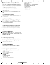
... original/play-list editing in Video mode The disc NAVI function, which was impossible with conventional models. Improved Still Picture menu in DVD-VR mode available with conventional models is displayed as a list. b Simultaneous recording/playback Playback of WMA, MP3, and JPEG formats is also supported. 4. E 6. a Pursuit playback Playback of conventional models. 1 2 New functions and specifications In this model, the following main functions and specifications adopted with conventional models are displayed with still pictures as an animated picture with sound. 3.
... original/play-list editing in Video mode The disc NAVI function, which was impossible with conventional models. Improved Still Picture menu in DVD-VR mode available with conventional models is displayed as a list. b Simultaneous recording/playback Playback of WMA, MP3, and JPEG formats is also supported. 4. E 6. a Pursuit playback Playback of conventional models. 1 2 New functions and specifications In this model, the following main functions and specifications adopted with conventional models are displayed with still pictures as an animated picture with sound. 3.

Service Manual
Page 115
...-R, CD-RW instances, check with KODAK Picture CD • is compatible with this recorder. / 999 files at one of the specification are playable) WMA (Windows Media Audio) compatibility DVD-Video DVD-R DVD-RW B Audio CD Video CD CD-R CD-RW The Windows Media® logo printed on the box indicates that this recorder can be used by digital still cameras • DVD-RW: Video Recording (VR) format and DVDVideo format (Video mode) • Sampling ratio: 4:4:4, 4:4:2, 4:2:0 • Horizontal resolution...
...-R, CD-RW instances, check with KODAK Picture CD • is compatible with this recorder. / 999 files at one of the specification are playable) WMA (Windows Media Audio) compatibility DVD-Video DVD-R DVD-RW B Audio CD Video CD CD-R CD-RW The Windows Media® logo printed on the box indicates that this recorder can be used by digital still cameras • DVD-RW: Video Recording (VR) format and DVDVideo format (Video mode) • Sampling ratio: 4:4:4, 4:4:2, 4:2:0 • Horizontal resolution...

Service Manual
Page 117
... other portable equipment. Press to directly access the Disc Navigator screen. 10 4 IR remote sensor Press to start or restart playback. 6 Front panel display See Display on /into standby. 2 DISC HISTORY Press to display the Disc History screen. 3 DISC NAVIGATOR Press repeatedly to change TV channels, skip chapters/tracks, etc. 13 0 OPEN/CLOSE Press to open/close the disc tray. 14 Front panel inputs Pull the cover down where indicated to stop recording. C 5 Disc tray 11 3 Press to start recording. Use to change the recording mode (picture...
... other portable equipment. Press to directly access the Disc Navigator screen. 10 4 IR remote sensor Press to start or restart playback. 6 Front panel display See Display on /into standby. 2 DISC HISTORY Press to display the Disc History screen. 3 DISC NAVIGATOR Press repeatedly to change TV channels, skip chapters/tracks, etc. 13 0 OPEN/CLOSE Press to open/close the disc tray. 14 Front panel inputs Pull the cover down where indicated to stop recording. C 5 Disc tray 11 3 Press to start recording. Use to change the recording mode (picture...

Service Manual
Page 118
... optical digital input. 7 AC IN Connect to a power outlet using a mini-plug cord. 6 OPTICAL DIGITAL OUT A digital audio output for connecting to an AV receiver, Dolby Digital/DTS decoder or other source component for connection to theVHF/UHF IN jack. 1 2 8.2 REAR PART Rear panel connections A 1 2 3 4 3 56 OUT IN VHF / UHF OUTPUT 1 R L R L INPUT 1/ AUTO START REC Y PB PR COMPONENT VIDEO OUT AUDIO VIDEO S-VIDEO OUTPUT 2 AUDIO VIDEO INPUT 3 S-VIDEO IN OPTICAL CONTROL DIGITAL OUT B 4 7 AC IN 1 VHF/UHF IN/OUT Connect your TV antenna to your TV. The signal is...
... optical digital input. 7 AC IN Connect to a power outlet using a mini-plug cord. 6 OPTICAL DIGITAL OUT A digital audio output for connecting to an AV receiver, Dolby Digital/DTS decoder or other source component for connection to theVHF/UHF IN jack. 1 2 8.2 REAR PART Rear panel connections A 1 2 3 4 3 56 OUT IN VHF / UHF OUTPUT 1 R L R L INPUT 1/ AUTO START REC Y PB PR COMPONENT VIDEO OUT AUDIO VIDEO S-VIDEO OUTPUT 2 AUDIO VIDEO INPUT 3 S-VIDEO IN OPTICAL CONTROL DIGITAL OUT B 4 7 AC IN 1 VHF/UHF IN/OUT Connect your TV antenna to your TV. The signal is...

Service Manual
Page 120
... screen, or the top menu if a DVD-Video disc is loaded. 11 PLAY LIST / MENU Press to switch between Original and Play List content on VR mode discs, or display the disc menu if a DVD-Video disc is loaded. 12 »/«/|/\ (cursor buttons)and ENTER Used to navigate all on discs with a TV and when setting the remote control mode E 2 STANDBY/ON Press to switch the recorder on/into standby. 3 0 OPEN/CLOSE Press to open/close the disc tray. 4 DVD playback functions AUDIO Changes the audio language or channel...
... screen, or the top menu if a DVD-Video disc is loaded. 11 PLAY LIST / MENU Press to switch between Original and Play List content on VR mode discs, or display the disc menu if a DVD-Video disc is loaded. 12 »/«/|/\ (cursor buttons)and ENTER Used to navigate all on discs with a TV and when setting the remote control mode E 2 STANDBY/ON Press to switch the recorder on/into standby. 3 0 OPEN/CLOSE Press to open/close the disc tray. 4 DVD playback functions AUDIO Changes the audio language or channel...


