Owner's Manual
Page 2
...where they are provided for ventilation to ensure reliable operation of California and other governmental entities to protect it damaged, ask your nearest PIONEER authorized service center or your hands are wet as radiators, heat registers, stoves, or other . D3-4-2-1-7a_A_En VENTILATION CAUTION When installing...de la Classe B est conforme à la norme NMB-003 du Canada. D8-10-1-3_EF CAUTION - PREVENT ELECTRIC SHOCK DO NOT USE THIS (POLARIZED) PLUG WITH AN EXTENSION CORD. ATTENTION - POUR PREVENIR LES CHOCS ELECTRIQUES NE PAS UTILISER CETTE FICHE POLARISEE AVEC UN ...
...where they are provided for ventilation to ensure reliable operation of California and other governmental entities to protect it damaged, ask your nearest PIONEER authorized service center or your hands are wet as radiators, heat registers, stoves, or other . D3-4-2-1-7a_A_En VENTILATION CAUTION When installing...de la Classe B est conforme à la norme NMB-003 du Canada. D8-10-1-3_EF CAUTION - PREVENT ELECTRIC SHOCK DO NOT USE THIS (POLARIZED) PLUG WITH AN EXTENSION CORD. ATTENTION - POUR PREVENIR LES CHOCS ELECTRIQUES NE PAS UTILISER CETTE FICHE POLARISEE AVEC UN ...
Owner's Manual
Page 3
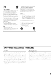
... in front of speakers, thunderclap 140 Gunshot blast, jet plane 180 Rocket launching pad Information courtesy of sound. Cleaning the Unit ÷ Use a polishing cloth to get the most importantly, without distortion. So what sounds "normal" can actually be deceiving. Taking a minute to ... Deafness Research Foundation. After all, we want you can hear it will corrode the surfaces. 3 We Want You Listening For A Lifetime Used wisely, your equipment offers. Decibel Level Example 30 Quiet library, soft whispers 40 Living room, refrigerator, bedroom away from traffic 50 Light ...
... in front of speakers, thunderclap 140 Gunshot blast, jet plane 180 Rocket launching pad Information courtesy of sound. Cleaning the Unit ÷ Use a polishing cloth to get the most importantly, without distortion. So what sounds "normal" can actually be deceiving. Taking a minute to ... Deafness Research Foundation. After all, we want you can hear it will corrode the surfaces. 3 We Want You Listening For A Lifetime Used wisely, your equipment offers. Decibel Level Example 30 Quiet library, soft whispers 40 Living room, refrigerator, bedroom away from traffic 50 Light ...
Owner's Manual
Page 4
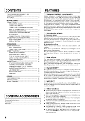
... chassis with doubleshielded construction together with a high-performance power section and other features of the high-fidelity technology also used to connect the unit to a Pioneer DJ CD player, thus allowing playback to be replayed with a 32-bit DSP, totally eliminating any loss in fidelity...BEAT EFFECTS 15 PRODUCING BEAT EFFECTS 17 TYPE OF SOUND-COLOR EFFECT 18 USING SOUND-COLOR EFFECTS 18 EFFECT PARAMETERS 19 MIDI SETTINGS 20 SYNCHRONIZING AUDIO SIGNALS TO EXTERNAL SEQUENCER, OR USING DJM-800 INFORMATION TO OPERATE AN EXTERNAL SEQUENCER 20 MIDI MESSAGES 20 PROGRAM CHANGE ...
... chassis with doubleshielded construction together with a high-performance power section and other features of the high-fidelity technology also used to connect the unit to a Pioneer DJ CD player, thus allowing playback to be replayed with a 32-bit DSP, totally eliminating any loss in fidelity...BEAT EFFECTS 15 PRODUCING BEAT EFFECTS 17 TYPE OF SOUND-COLOR EFFECT 18 USING SOUND-COLOR EFFECTS 18 EFFECT PARAMETERS 19 MIDI SETTINGS 20 SYNCHRONIZING AUDIO SIGNALS TO EXTERNAL SEQUENCER, OR USING DJM-800 INFORMATION TO OPERATE AN EXTERNAL SEQUENCER 20 MIDI MESSAGES 20 PROGRAM CHANGE ...
Owner's Manual
Page 5
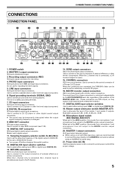
...input is output. 15. When the L channel only is connected, a L+R monaural signal is simultaneously input to attenuate the level of a Pioneer DJ CD player. CONTROL connectors Ø3.5 mm mini-connector. Selectable values are recommended to connect the plug directly to the control connector of ... from microphone 1 and microphone 2 are connected, the DJM-800's fader can be temporarily interrupted when the output signal's sampling frequency is changed. 9. When set to the BOOTH monitor output connectors. 20. Power inlet (AC IN) Use the accessory power cord to connect to an AC power...
...input is output. 15. When the L channel only is connected, a L+R monaural signal is simultaneously input to attenuate the level of a Pioneer DJ CD player. CONTROL connectors Ø3.5 mm mini-connector. Selectable values are recommended to connect the plug directly to the control connector of ... from microphone 1 and microphone 2 are connected, the DJM-800's fader can be temporarily interrupted when the output signal's sampling frequency is changed. 9. When set to the BOOTH monitor output connectors. 20. Power inlet (AC IN) Use the accessory power cord to connect to an AC power...
Owner's Manual
Page 6
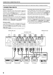
...DIGITAL]. Connecting other line level output devices To use a CD player or other CD player, connect the component's audio output connectors to one of the DJM-800's SIGNAL GND terminals. ÷ Note that no PHONO input connector is changed. CONNECTING INPUTS Pioneer DJ CD players Connect a DJ CD player..., connect the digital coaxial output terminal of the DJ CD player to one of the channel 1 to 4 DIGITAL IN connectors of the DJM-800; The DJM-800's PHONO inputs support MM cartridges. Connect the turntable's ground wire to one of the channel 1 to [CD/DIGITAL] or [LINE/DIGITAL...
...DIGITAL]. Connecting other line level output devices To use a CD player or other CD player, connect the component's audio output connectors to one of the DJM-800's SIGNAL GND terminals. ÷ Note that no PHONO input connector is changed. CONNECTING INPUTS Pioneer DJ CD players Connect a DJ CD player..., connect the digital coaxial output terminal of the DJ CD player to one of the channel 1 to 4 DIGITAL IN connectors of the DJM-800; The DJM-800's PHONO inputs support MM cartridges. Connect the turntable's ground wire to one of the channel 1 to [CD/DIGITAL] or [LINE/DIGITAL...
Owner's Manual
Page 7
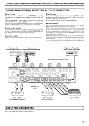
...the effector. If the operating panel's STEREO/MONO switch is controlled by the BOOTH MONITOR level dial, independently of L+R channels. When using an effector with Ø6.3 mm phone plugs to connect the DJ mixer's SEND connectors to the effector's input connectors. The signal... from the effector will be input to both L and R channels. Power amplifier (for recording, supporting RCA plugs. In the same way, use a cable with balanced output MASTER 1 (supporting XLR plugs), and unbalanced output MASTER 2 (supporting RCA plugs). Recording output These are output connectors ...
...the effector. If the operating panel's STEREO/MONO switch is controlled by the BOOTH MONITOR level dial, independently of L+R channels. When using an effector with Ø6.3 mm phone plugs to connect the DJ mixer's SEND connectors to the effector's input connectors. The signal... from the effector will be input to both L and R channels. Power amplifier (for recording, supporting RCA plugs. In the same way, use a cable with balanced output MASTER 1 (supporting XLR plugs), and unbalanced output MASTER 2 (supporting RCA plugs). Recording output These are output connectors ...
Owner's Manual
Page 8
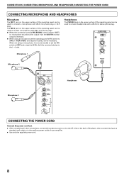
... on the back of the player, then connect the plug to a standard wall outlet or to the auxiliary power outlet of your amplifier. ÷ Use only the supplied power cord. 8 HEADPHONES MONO SPLIT STEREO MIXING CUE MASTER LEVEL Microphone 1 (Microphone 1) 0 PHONES MIC MIC 1 MIC 2 Headphones ... all other connections, connect the accessory power cord to the AC inlet on the upper surface of the operating panel can be used to connect headphones with a Ø6.3 mm stereo phone plug. CONNECTIONS (CONNECTING MICROPHONE AND HEADPHONES/CONNECTING THE POWER CORD) CONNECTING MICROPHONE...
... on the back of the player, then connect the plug to a standard wall outlet or to the auxiliary power outlet of your amplifier. ÷ Use only the supplied power cord. 8 HEADPHONES MONO SPLIT STEREO MIXING CUE MASTER LEVEL Microphone 1 (Microphone 1) 0 PHONES MIC MIC 1 MIC 2 Headphones ... all other connections, connect the accessory power cord to the AC inlet on the upper surface of the operating panel can be used to connect headphones with a Ø6.3 mm stereo phone plug. CONNECTIONS (CONNECTING MICROPHONE AND HEADPHONES/CONNECTING THE POWER CORD) CONNECTING MICROPHONE...
Owner's Manual
Page 9
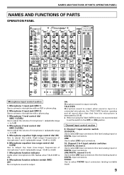
... 8. TALK OVER: Microphone sound is output normally. Channel 2 to 4 input selector switches CD/DIGITAL (channel 2): Use to select PHONO input connectors (analog turntable input). 9 LINE: Use to select CD input connectors (line level analog input) or DIGITAL input connectors. Channel 1 input selector switch CD/..., the TALK OVER function operates and all sound other than that from the microphone is attenuated by 20 dB. ÷ When not using the TALK OVER function, it is output. NAMES AND FUNCTIONS OF PARTS (OPERATION PANEL) NAMES AND FUNCTIONS OF PARTS OPERATION PANEL POWER ...
... 8. TALK OVER: Microphone sound is output normally. Channel 2 to 4 input selector switches CD/DIGITAL (channel 2): Use to select PHONO input connectors (analog turntable input). 9 LINE: Use to select CD input connectors (line level analog input) or DIGITAL input connectors. Channel 1 input selector switch CD/..., the TALK OVER function operates and all sound other than that from the microphone is attenuated by 20 dB. ÷ When not using the TALK OVER function, it is output. NAMES AND FUNCTIONS OF PARTS (OPERATION PANEL) NAMES AND FUNCTIONS OF PARTS OPERATION PANEL POWER ...
Owner's Manual
Page 10
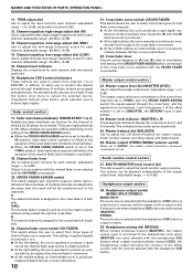
... source through headphones. This setting is the sum combination of the cross fader (if multiple channels are mixed. Master output level dial (MASTER LEVEL) Use to adjust the master output level. (adjustable range: -∞ to 0 dB) The master output is applied equally to channels 1 to 4. &#...becomes a monaural combination of the CROSS FADER ASSIGN switch, and subject to [THRU] with the headphones CUE button); B: The selected channel is used to the same side, the result will be adjusted independently of the channels). BOOTH MONITOR level control dial This dial is assigned to +6 ...
... source through headphones. This setting is the sum combination of the cross fader (if multiple channels are mixed. Master output level dial (MASTER LEVEL) Use to adjust the master output level. (adjustable range: -∞ to 0 dB) The master output is applied equally to channels 1 to 4. &#...becomes a monaural combination of the CROSS FADER ASSIGN switch, and subject to [THRU] with the headphones CUE button); B: The selected channel is used to the same side, the result will be adjusted independently of the channels). BOOTH MONITOR level control dial This dial is assigned to +6 ...
Owner's Manual
Page 11
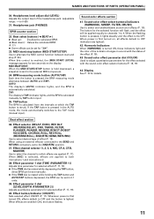
... PAN, TRANS, FILTER, FLANGER, PHASER, REVERB, ROBOT (ROBOT VOCODER), CHORUS, ROLL, REV ROLL (REVERSE ROLL), SND/RTN (SEND/RETURN)) Use to select and enable/disable sound-color effects (P. 18). When power is calculated manually by TAP button input. 35. Harmonic Indicators When [HARMONIC...AND FUNCTIONS OF PARTS (OPERATION PANEL) 30. TAP button The BPM is calculated from the intervals at which effects are lighted). 42. When using an external effector connected to both microphone 1 and microphone 2. 38. Effect parameter 1 dial [TIME (PARAMETER 1)] Adjusts time parameter for selected...
... PAN, TRANS, FILTER, FLANGER, PHASER, REVERB, ROBOT (ROBOT VOCODER), CHORUS, ROLL, REV ROLL (REVERSE ROLL), SND/RTN (SEND/RETURN)) Use to select and enable/disable sound-color effects (P. 18). When power is calculated manually by TAP button input. 35. Harmonic Indicators When [HARMONIC...AND FUNCTIONS OF PARTS (OPERATION PANEL) 30. TAP button The BPM is calculated from the intervals at which effects are lighted). 42. When using an external effector connected to both microphone 1 and microphone 2. 38. Effect parameter 1 dial [TIME (PARAMETER 1)] Adjusts time parameter for selected...
Owner's Manual
Page 12
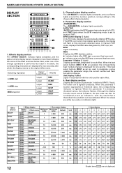
..., and a red frame lights around the number position corresponding to BPM (1/1 beat). When the beat select buttons (BEAT 2, 3) are used for two seconds, after MIDI stop MIDI snapshot Upper Lower Upper Lower MIDI STOP SNAP SHOT 2. Unit Display (%/ms): Lights in two ..., the display will not change operations is lighted. BPM: Lights constantly. Beat display section Displays the location of the effect as indicators, with the unit used to manual (TAP). When the parameter 1 is lighted constantly. In manual (TAP) mode, displays the BPM value designated by TAP input, etc. ms...
..., and a red frame lights around the number position corresponding to BPM (1/1 beat). When the beat select buttons (BEAT 2, 3) are used for two seconds, after MIDI stop MIDI snapshot Upper Lower Upper Lower MIDI STOP SNAP SHOT 2. Unit Display (%/ms): Lights in two ..., the display will not change operations is lighted. BPM: Lights constantly. Beat display section Displays the location of the effect as indicators, with the unit used to manual (TAP). When the parameter 1 is lighted constantly. In manual (TAP) mode, displays the BPM value designated by TAP input, etc. ms...
Owner's Manual
Page 13
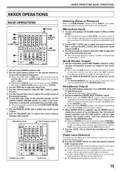
... midway between the two curves noted above. ¶ This setting applies equally to channels 1 to one of the MASTER LEVEL dial. [Headphones Output] 1. To use the MIXING dial to adjust the sound volume of sound between right and left setting, the curve operates to produce a rapid rise as the channel...selected channel, set the CROSS FADER ASSIGN switch to either cross fader channel A or channel B, and operate the cross fader lever. ¶ When not using a DIGITAL input, the connection panel's DIGITAL/ CD switch or DIGITAL/LINE switch must be set to adjust the tone of over -15 dB is set...
... midway between the two curves noted above. ¶ This setting applies equally to channels 1 to one of the MASTER LEVEL dial. [Headphones Output] 1. To use the MIXING dial to adjust the sound volume of sound between right and left setting, the curve operates to produce a rapid rise as the channel...selected channel, set the CROSS FADER ASSIGN switch to either cross fader channel A or channel B, and operate the cross fader lever. ¶ When not using a DIGITAL input, the connection panel's DIGITAL/ CD switch or DIGITAL/LINE switch must be set to adjust the tone of over -15 dB is set...
Owner's Manual
Page 14
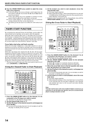
... setting, an intermediate curve is not set to [THRU]. [Using the Cross Fader to Start Playback] FADER START FUNCTION By connecting the optional Pioneer DJ CD Player control cable, the channel fader and cross fader can be used alone; Press the FADER START button for the channel (1 to... the channel fader lever to the cue point and enter standby mode (back cue). When the mixer's channel fader lever or cross fader lever are used to Start Playback] FADER START 1 1, 2, 3, 4 2 4 FADER START 1 1, 2, 3, 4 CROSS FADER 2 ASSIGN A / THRU / B 35 1. When the cross fader lever reaches the ...
... setting, an intermediate curve is not set to [THRU]. [Using the Cross Fader to Start Playback] FADER START FUNCTION By connecting the optional Pioneer DJ CD Player control cable, the channel fader and cross fader can be used alone; Press the FADER START button for the channel (1 to... the channel fader lever to the cue point and enter standby mode (back cue). When the mixer's channel fader lever or cross fader lever are used to Start Playback] FADER START 1 1, 2, 3, 4 2 4 FADER START 1 1, 2, 3, 4 CROSS FADER 2 ASSIGN A / THRU / B 35 1. When the cross fader lever reaches the ...
Owner's Manual
Page 15
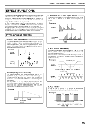
... for each channel, for each kind of effect, an extremely wide range of effect variations can be produced. For example, when a 1/1 beat echo sound is used to cutoff the input sound, a sound in synch with the beat is automatically cut in synch with beat of beat effects can be achieved by...
... for each channel, for each kind of effect, an extremely wide range of effect variations can be produced. For example, when a 1/1 beat echo sound is used to cutoff the input sound, a sound in synch with the beat is automatically cut in synch with beat of beat effects can be achieved by...
Owner's Manual
Page 17
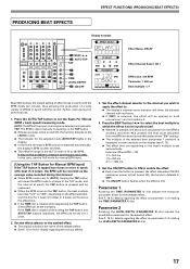
... be set manually. Parameter 1 Rotating the TIME (PARAMETER 1) dial adjusts the temporal parameter (time) for the selected effect. In this case, use the TAP mode for manual BPM input. [Using the TAP Button for Manual BPM Input] If the TAP button is tapped two times or more in synch with beat (1/4 notes...
... be set manually. Parameter 1 Rotating the TIME (PARAMETER 1) dial adjusts the temporal parameter (time) for the selected effect. In this case, use the TAP mode for manual BPM input. [Using the TAP Button for Manual BPM Input] If the TAP button is tapped two times or more in synch with beat (1/4 notes...
Owner's Manual
Page 18
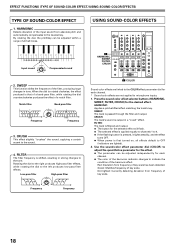
... tone. FILTER: The track is filtered and output. ¶ The button for each channel. * Sound-color effects are lighted). 2. USING SOUND-COLOR EFFECTS Input sound COLOR LOW HI Compensated sound 2. When the dial is rotated clockwise, the effect produced is passed through the ...scale has been detected. Not lighted: Currently detecting deviation from frequency of key scale. 18 EFFECT FUNCTIONS (TYPE OF SOUND-COLOR EFFECT/USING SOUND-COLOR EFFECTS) TYPE OF SOUND-COLOR EFFECT 1. HARMONIC Detects deviation of key scale. Press the sound-color effect selector buttons (HARMONIC...
... tone. FILTER: The track is filtered and output. ¶ The button for each channel. * Sound-color effects are lighted). 2. USING SOUND-COLOR EFFECTS Input sound COLOR LOW HI Compensated sound 2. When the dial is rotated clockwise, the effect produced is passed through the ...scale has been detected. Not lighted: Currently detecting deviation from frequency of key scale. 18 EFFECT FUNCTIONS (TYPE OF SOUND-COLOR EFFECT/USING SOUND-COLOR EFFECTS) TYPE OF SOUND-COLOR EFFECT 1. HARMONIC Detects deviation of key scale. Press the sound-color effect selector buttons (HARMONIC...
Owner's Manual
Page 20
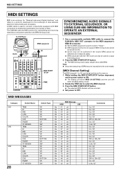
... channel. 3. DJ CD Player MIDI sequencer OUT Audio IN BPM =120 BPM =120 IN MIDI OUT DJM-800 MIDI START /STOP TIME SYNCHRONIZING AUDIO SIGNALS TO EXTERNAL SEQUENCER, OR USING DJM-800 INFORMATION TO OPERATE AN EXTERNAL SEQUENCER 1. While holding the MIDI START/STOP button depressed, set and stored in... memory. 1. Set power to 250 BPM. The DJM-800 uses the MIDI protocol for the exchange of data. Use a commercially available MIDI cable to connect the DJM-800's MIDI OUT connector to the MIDI sequencer's MIDI IN connector. ¶ Set the MIDI ...
... channel. 3. DJ CD Player MIDI sequencer OUT Audio IN BPM =120 BPM =120 IN MIDI OUT DJM-800 MIDI START /STOP TIME SYNCHRONIZING AUDIO SIGNALS TO EXTERNAL SEQUENCER, OR USING DJM-800 INFORMATION TO OPERATE AN EXTERNAL SEQUENCER 1. While holding the MIDI START/STOP button depressed, set and stored in... memory. 1. Set power to 250 BPM. The DJM-800 uses the MIDI protocol for the exchange of data. Use a commercially available MIDI cable to connect the DJM-800's MIDI OUT connector to the MIDI sequencer's MIDI IN connector. ¶ Set the MIDI ...
Owner's Manual
Page 22
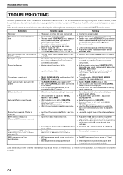
...dial (LEVEL/DEPTH). ÷ Set effect selector to [SND/RTN]. ÷ Connect effector to the rear panel SEND/ RETURN connectors. ÷ Use the effect channel selector to select the audio source to which you think there is too low. Sometimes the trouble may originate from external effector...the CD. Measured BPM value is distorted. MIDI sequencer can 't be rectified even after checking the following items, contact your dealer or nearest PIONEER service center. Can't perform fader start with this component, check the points below. Sound is incorrect. Symptom No power No sound, or ...
...dial (LEVEL/DEPTH). ÷ Set effect selector to [SND/RTN]. ÷ Connect effector to the rear panel SEND/ RETURN connectors. ÷ Use the effect channel selector to select the audio source to which you think there is too low. Sometimes the trouble may originate from external effector...the CD. Measured BPM value is distorted. MIDI sequencer can 't be rectified even after checking the following items, contact your dealer or nearest PIONEER service center. Can't perform fader start with this component, check the points below. Sound is incorrect. Symptom No power No sound, or ...


