Manual
Page 2
... Nighttime 12 Resetting the Microprocessor 12 Operation of the Display 13 Deploying the Display 13 Screen Angle Adjustment 14 Closing the Display 15 Brightness Adjustment 16 Switching the Auto-Dimmer Mode 16 Changing the Wide Mode 17 • Just (JUST) • Full (FULL) • Cinema (CINEMA) • Zoom (ZOOM) • Normal (NORMAL) Canceling the Automatic Close/Open Mode 18 Switching the Illumination Color 19 Detaching and Replacing the Front...
... Nighttime 12 Resetting the Microprocessor 12 Operation of the Display 13 Deploying the Display 13 Screen Angle Adjustment 14 Closing the Display 15 Brightness Adjustment 16 Switching the Auto-Dimmer Mode 16 Changing the Wide Mode 17 • Just (JUST) • Full (FULL) • Cinema (CINEMA) • Zoom (ZOOM) • Normal (NORMAL) Canceling the Automatic Close/Open Mode 18 Switching the Illumination Color 19 Detaching and Replacing the Front...
Manual
Page 3
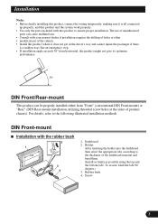
... installation. • Before finally installing this product, connect the wiring temporarily, making sure it does not get in the driver's way and cannot injure the passenger if there is all connected up properly, and this product and the system work properly. • Use only the parts included with this product might not give its optimum performance. 30° DIN Front/Rear...
... installation. • Before finally installing this product, connect the wiring temporarily, making sure it does not get in the driver's way and cannot injure the passenger if there is all connected up properly, and this product and the system work properly. • Use only the parts included with this product might not give its optimum performance. 30° DIN Front/Rear...
Manual
Page 4
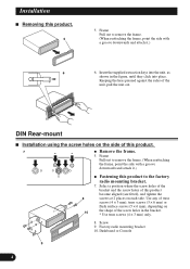
... frame, point the side with a groove downwards and attach it .) 7. DIN Rear-mount Installation using the screw holes on 10 the shape of this product. 7 * * 5. Frame Pull out to remove the frame. (When reattaching the frame, point the side with a groove downwards ...and attach it .) 6 6. Select a position where the screw holes of the bracket and the screw holes of the unit, pull the unit out. Keeping the keys pressed against the sides of this product. 5 5. Factory radio...
... frame, point the side with a groove downwards and attach it .) 7. DIN Rear-mount Installation using the screw holes on 10 the shape of this product. 7 * * 5. Frame Pull out to remove the frame. (When reattaching the frame, point the side with a groove downwards ...and attach it .) 6 6. Select a position where the screw holes of the bracket and the screw holes of the unit, pull the unit out. Keeping the keys pressed against the sides of this product. 5 5. Factory radio...
Manual
Page 5
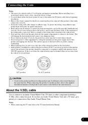
... connection of the Audio Visual Master Unit. • When connecting the TV tuner refer to the battery. About the V.SEL cable Use to connect to the owner's manual for several hours. Do not route wiring in the electrical system, be drained when you have the same function. If you are away from the vehicle for details on the ignition switch, the red lead of this is installed...
... connection of the Audio Visual Master Unit. • When connecting the TV tuner refer to the battery. About the V.SEL cable Use to connect to the owner's manual for several hours. Do not route wiring in the electrical system, be drained when you have the same function. If you are away from the vehicle for details on the ignition switch, the red lead of this is installed...

Manual
Page 6
Fuse resistor Orange To lighting switch terminal. Fuse resistor Black (ground) To vehicle (metal) body. This Product Yellow To terminal always supplied with power regardless of ignition switch position. Connecting the Power Cord • This product conforms to new cord colors. Fuse holder Red To electric terminal controlled by ignition switch (12 V DC) ON/OFF.
Fuse resistor Orange To lighting switch terminal. Fuse resistor Black (ground) To vehicle (metal) body. This Product Yellow To terminal always supplied with power regardless of ignition switch position. Connecting the Power Cord • This product conforms to new cord colors. Fuse holder Red To electric terminal controlled by ignition switch (12 V DC) ON/OFF.

Manual
Page 7
Connecting the System (A) Speaker Unit (supplied) Navigation System (sold separately) This Product 3 m Not Used. 15 cm Gray 3m RGB cable (supplied) 50 cm Green Gray
Connecting the System (A) Speaker Unit (supplied) Navigation System (sold separately) This Product 3 m Not Used. 15 cm Gray 3m RGB cable (supplied) 50 cm Green Gray

Manual
Page 8
You cannot use a V.SEL cable with the Audio Visual V.SEL cable Master Unit) (supplied) 6m Gray This Product t 3m Speaker Unit (supplied) 15 cm Blue Multi-CD player (sold separately) RGB cable (supplied with this kind of Audio Visual Master Unit. Connecting the System (B) Navigation System (sold separately) Green Gray Green Audio Visual Master Unit (sold separately) 3m 50 cm Green Gray RGB cable (supplied) • Some Audio Visual Master Units may not feature a V.SEL cable connection jack.
You cannot use a V.SEL cable with the Audio Visual V.SEL cable Master Unit) (supplied) 6m Gray This Product t 3m Speaker Unit (supplied) 15 cm Blue Multi-CD player (sold separately) RGB cable (supplied with this kind of Audio Visual Master Unit. Connecting the System (B) Navigation System (sold separately) Green Gray Green Audio Visual Master Unit (sold separately) 3m 50 cm Green Gray RGB cable (supplied) • Some Audio Visual Master Units may not feature a V.SEL cable connection jack.
Manual
Page 9
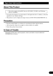
... the operation of Trouble Should this product fail to operate properly, contact your vehicle's air bags. • This product is used to be audible. • Protect this manual handy as a reference for operating procedures and precautions. • Always keep the volume low enough for outside sounds to display the images from moisture. In Case of your dealer or nearest authorized PIONEER Service Station.
... the operation of Trouble Should this product fail to operate properly, contact your vehicle's air bags. • This product is used to be audible. • Protect this manual handy as a reference for operating procedures and precautions. • Always keep the volume low enough for outside sounds to display the images from moisture. In Case of your dealer or nearest authorized PIONEER Service Station.
Manual
Page 10
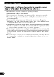
... the safe operation of these instructions regarding your display and retain them for future reference. 3. Installation or servicing of any accessory in this manual fully and carefully before making adjustments. 7. Please read and understood the operating instructions. 5. Do not attempt to install or service your display by persons without training and experience in electronic equipment and automotive accessories may obstruct the driver's vision, impair...
... the safe operation of these instructions regarding your display and retain them for future reference. 3. Installation or servicing of any accessory in this manual fully and carefully before making adjustments. 7. Please read and understood the operating instructions. 5. Do not attempt to install or service your display by persons without training and experience in electronic equipment and automotive accessories may obstruct the driver's vision, impair...

Manual
Page 11
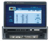
This Product The following diagram shows the display when it is deployed. Display Wide mode indicators DIM button BRIGHTNESS button Release Section RESET button WIDE button ANGLE button Signal Receptor OPEN/CLOSE button • Use the remote control products for the AUDIO VISUAL MASTER UNIT by pointing them at this product's signal receptor.
This Product The following diagram shows the display when it is deployed. Display Wide mode indicators DIM button BRIGHTNESS button Release Section RESET button WIDE button ANGLE button Signal Receptor OPEN/CLOSE button • Use the remote control products for the AUDIO VISUAL MASTER UNIT by pointing them at this product's signal receptor.
Manual
Page 12
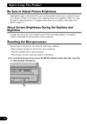
Resetting the Microprocessor The microprocessor must be positioned and viewed clearly is limited because of the surrounding darkness. Turning the vehicle's inside light on the display. When strange (incorrect) messages appear on will lessen the screen's brightness. Be Sure to operate properly. - When the machine fails to Adjust Picture Brightness Although the angle at the angle of use. (Refer to page 16.) About Screen Brightness During the...
Resetting the Microprocessor The microprocessor must be positioned and viewed clearly is limited because of the surrounding darkness. Turning the vehicle's inside light on the display. When strange (incorrect) messages appear on will lessen the screen's brightness. Be Sure to operate properly. - When the machine fails to Adjust Picture Brightness Although the angle at the angle of use. (Refer to page 16.) About Screen Brightness During the...
Manual
Page 13
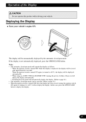
... using an AUDIO VISUAL MASTER UNIT, turning the power of either of these on will deploy the display automatically. * Installing the front panel will automatically deploy the display. (Refer to page 16.) • When the ignition switch is deployed, the display will be automatically deployed by the automatic close /open mode will operate the display as follows. * When the ignition switch is turned OFF while the display is turned...
... using an AUDIO VISUAL MASTER UNIT, turning the power of either of these on will deploy the display automatically. * Installing the front panel will automatically deploy the display. (Refer to page 16.) • When the ignition switch is deployed, the display will be automatically deployed by the automatic close /open mode will operate the display as follows. * When the ignition switch is turned OFF while the display is turned...

Manual
Page 14
Screen Angle Adjustment The angle of the display will be sure to the next time the display is deployed. Forcible adjusting of the display by hand may damage it. • The adjusted angle of this product's screen continues changing as long as you keep pressing the ANGLE button. • If you can hear the display knocking against your vehicle's console or dashboard, press the ANGLE button on the (-) side to move the screen a little forward. • When adjusting the angle, be memorized and automatically returned to press the ANGLE button.
Screen Angle Adjustment The angle of the display will be sure to the next time the display is deployed. Forcible adjusting of the display by hand may damage it. • The adjusted angle of this product's screen continues changing as long as you keep pressing the ANGLE button. • If you can hear the display knocking against your vehicle's console or dashboard, press the ANGLE button on the (-) side to move the screen a little forward. • When adjusting the angle, be memorized and automatically returned to press the ANGLE button.
Manual
Page 16
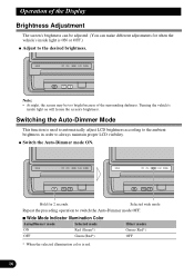
... Mode This function is used to automatically adjust LCD brightness according to the ambient brightness in order to switch the Auto-Dimmer mode OFF. Wide Mode Indicator Illumination Color ON Red (Green*) OFF Green (Red*) * When the selected illumination color is ON or OFF.) • At night, the screen may be adjusted. (You can make different adjustments for 2 seconds Selected wide mode Repeat the preceding operation to always maintain proper LCD visibility. Turning...
... Mode This function is used to automatically adjust LCD brightness according to the ambient brightness in order to switch the Auto-Dimmer mode OFF. Wide Mode Indicator Illumination Color ON Red (Green*) OFF Green (Red*) * When the selected illumination color is ON or OFF.) • At night, the screen may be adjusted. (You can make different adjustments for 2 seconds Selected wide mode Repeat the preceding operation to always maintain proper LCD visibility. Turning...
Manual
Page 17
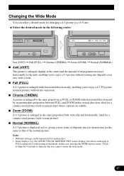
... irrespective of the setting of enlargement increases horizontally to the ends, enabling you cannot switch the wide mode. Cinema (CINEMA) A picture is , giving you to a 16:9 one. Full (FULL) A 4:3 picture is enlarged in the vertical direction; In this mode. Changing the Wide Mode You can be memorized for each picture. • Some displays (e.g. ideal for a cinema-sized picture (wide-screen picture) where captions...
... irrespective of the setting of enlargement increases horizontally to the ends, enabling you cannot switch the wide mode. Cinema (CINEMA) A picture is , giving you to a 16:9 one. Full (FULL) A 4:3 picture is enlarged in the vertical direction; In this mode. Changing the Wide Mode You can be memorized for each picture. • Some displays (e.g. ideal for a cinema-sized picture (wide-screen picture) where captions...

Manual
Page 18
... display, press the OPEN/CLOSE button. Repeat the preceding operation to turn the automatic close/open mode on. • This procedure can also be used to cancel the automatic close/open mode when the display is in the open position. • The automatic close/open mode can also be canceled by pressing the OPEN/CLOSE button while attaching the front panel. • When the ignition switch was turned...
... display, press the OPEN/CLOSE button. Repeat the preceding operation to turn the automatic close/open mode on. • This procedure can also be used to cancel the automatic close/open mode when the display is in the open position. • The automatic close/open mode can also be canceled by pressing the OPEN/CLOSE button while attaching the front panel. • When the ignition switch was turned...
Manual
Page 21
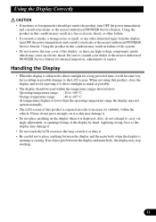
...remove the rear cover of the display, as this product is subjected to the LCD screen. Applying strong force to the display may damage it. • Do not touch the LCD screen as there are high-voltage components inside the product, turn OFF the power immediately and consult your dealer or the nearest authorized PIONEER Service Station...the operating temperature range the display may not operate normally. • The LCD screen of the display by hand. CAUTION • If moisture or foreign matter should be used within the vehicle. Using the product in this product, close the display ...
...remove the rear cover of the display, as this product is subjected to the LCD screen. Applying strong force to the display may damage it. • Do not touch the LCD screen as there are high-voltage components inside the product, turn OFF the power immediately and consult your dealer or the nearest authorized PIONEER Service Station...the operating temperature range the display may not operate normally. • The LCD screen of the display by hand. CAUTION • If moisture or foreign matter should be used within the vehicle. Using the product in this product, close the display ...
Manual
Page 22
... care not to form inside the display may be shortened. • Small black dots or white dots (bright dots) may become dark, or the life span of its useful life, the screen will be dark and the image will be difficult to see if it . Also, if the display is turned ON. • The LCD screen will no longer be dark...
... care not to form inside the display may be shortened. • Small black dots or white dots (bright dots) may become dark, or the life span of its useful life, the screen will be dark and the image will be difficult to see if it . Also, if the display is turned ON. • The LCD screen will no longer be dark...

Manual
Page 23
...Display Screen size/Aspect ratio 7 inch wide/16:9 (effective display area: 154 × 87 mm) Pixels 336,960 (1,440 × 234) Type TFT active matrix, transmissive type Color system NTSC/PAL/SECAM Compatible Operating temperature range 20 to +60° C Storage temperature range 40 to +85° C Angle Adjustment 60 - 110° Initial setting angle 90° • Specifications...size) ......... 178 (W) × 50 (H) × 165 (D) mm (front face 170 (W) × 46 (H) × 22 (D) mm (max. General Power source 14.4 V DC (10.8 - 15.1 V allowable) Grounding system Negative type Max.
...Display Screen size/Aspect ratio 7 inch wide/16:9 (effective display area: 154 × 87 mm) Pixels 336,960 (1,440 × 234) Type TFT active matrix, transmissive type Color system NTSC/PAL/SECAM Compatible Operating temperature range 20 to +60° C Storage temperature range 40 to +85° C Angle Adjustment 60 - 110° Initial setting angle 90° • Specifications...size) ......... 178 (W) × 50 (H) × 165 (D) mm (front face 170 (W) × 46 (H) × 22 (D) mm (max. General Power source 14.4 V DC (10.8 - 15.1 V allowable) Grounding system Negative type Max.
Manual
Page 24
...-4411 PIONEER ELECTRONICS DE MEXICO, S.A. Del Valle, Mexico D.F. All rights reserved. San Lorenzo Num 1009 3er piso Desp. 302 Col. C.P. 03100 TEL: 5-688-52-90 Published by Pioneer Electronic Corporation. TEL: (800) 421-1404 PIONEER ELECTRONIC (EUROPE) N.V. Printed in Belgium MAN-AVX-7000-GB/B Copyright © 1999 by Pioneer Electronic Corporation. France: tapez 36 15 PIONEER PIONEER ELECTRONIC CORPORATION...
...-4411 PIONEER ELECTRONICS DE MEXICO, S.A. Del Valle, Mexico D.F. All rights reserved. San Lorenzo Num 1009 3er piso Desp. 302 Col. C.P. 03100 TEL: 5-688-52-90 Published by Pioneer Electronic Corporation. TEL: (800) 421-1404 PIONEER ELECTRONIC (EUROPE) N.V. Printed in Belgium MAN-AVX-7000-GB/B Copyright © 1999 by Pioneer Electronic Corporation. France: tapez 36 15 PIONEER PIONEER ELECTRONIC CORPORATION...


