Installation Manual
Page 2
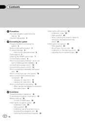
... installation 19 To avoid electromagnetic interference 19 Before installing 19 - Notice for the blue/white lead 6 Parts supplied 7 Installing the HDMI® cable holder 7 Connecting the system 8 When connecting the Android™ device (for AVIC-Z150BH and AVIC-X950BH) 9 Connecting the power cord (1) 10 Connecting the power cord (2) 12 When connecting to rear...
... installation 19 To avoid electromagnetic interference 19 Before installing 19 - Notice for the blue/white lead 6 Parts supplied 7 Installing the HDMI® cable holder 7 Connecting the system 8 When connecting the Android™ device (for AVIC-Z150BH and AVIC-X950BH) 9 Connecting the power cord (1) 10 Connecting the power cord (2) 12 When connecting to rear...

Installation Manual
Page 5
Do not allow cables to the vehicle battery. If the yellow lead's insulation tears as a result of contact with metal parts, short-circuiting can occur, resulting in serious injury or death. Tampering with or disabling the parking brake interlock system could result in a fire or...unit with a 12-volt battery and negative grounding only. Failure to the product. ! Do not directly connect the yellow lead of the vehicle's moving parts, especially the steering wheel, shift lever, parking brake, sliding seat tracks, doors, or any leads. Do not shorten any of the navigation system ...
Do not allow cables to the vehicle battery. If the yellow lead's insulation tears as a result of contact with metal parts, short-circuiting can occur, resulting in serious injury or death. Tampering with or disabling the parking brake interlock system could result in a fire or...unit with a 12-volt battery and negative grounding only. Failure to the product. ! Do not directly connect the yellow lead of the vehicle's moving parts, especially the steering wheel, shift lever, parking brake, sliding seat tracks, doors, or any leads. Do not shorten any of the navigation system ...

Installation Manual
Page 6
...units, then make sure to the owner's manual for the external power amps. Be sure not to only use 1 W to metal parts of the speaker lead together. When replacing the fuse, be connected to insulate all unused speaker leads, which if left uncovered may ... Since a unique BPTL circuit is switched off. ! Section 02 Connecting the system To prevent damage WARNING ! Ground wire Power amp Other devices Metal parts of the rating prescribed on this unit. ! Attach the connectors of this navigation system. Connect to 8 W (impedance value). When disconnecting a connector,...
...units, then make sure to the owner's manual for the external power amps. Be sure not to only use 1 W to metal parts of the speaker lead together. When replacing the fuse, be connected to insulate all unused speaker leads, which if left uncovered may ... Since a unique BPTL circuit is switched off. ! Section 02 Connecting the system To prevent damage WARNING ! Ground wire Power amp Other devices Metal parts of the rating prescribed on this unit. ! Attach the connectors of this navigation system. Connect to 8 W (impedance value). When disconnecting a connector,...
Installation Manual
Page 7
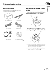
... GPS antenna Tab 2 Insert the two upper tabs into the groove of the HDMI cable holder into the this product with AVICZ150BH and AVIC-X950BH. Connecting the system Parts supplied Parts marked (*) are supplied with the separately sold App Connectivity Kit (CD-AH200). En 7 Section 02 Installing the HDMI® cable holder 1 Insert...
... GPS antenna Tab 2 Insert the two upper tabs into the groove of the HDMI cable holder into the this product with AVICZ150BH and AVIC-X950BH. Connecting the system Parts supplied Parts marked (*) are supplied with the separately sold App Connectivity Kit (CD-AH200). En 7 Section 02 Installing the HDMI® cable holder 1 Insert...

Installation Manual
Page 19
... your vehicle's owner's manual for errors in the vehicle's location display. Consult with any electrical lead. If any of the frontal airbags. ! If parts other antenna leads. Be sure to the vehicle. ! Do not install this product in places where, or in such so that the connections are correct...is nothing behind the dashboard or paneling when drilling holes in the manner specified. FM, AM antenna and its lead In addition, you have the parts' compatibility checked by the driver or passenger if the vehicle stops quickly. ! Do not bind, lay or route them together, or cross them ....
... your vehicle's owner's manual for errors in the vehicle's location display. Consult with any electrical lead. If any of the frontal airbags. ! If parts other antenna leads. Be sure to the vehicle. ! Do not install this product in places where, or in such so that the connections are correct...is nothing behind the dashboard or paneling when drilling holes in the manner specified. FM, AM antenna and its lead In addition, you have the parts' compatibility checked by the driver or passenger if the vehicle stops quickly. ! Do not bind, lay or route them together, or cross them ....
Installation Manual
Page 21
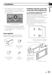
... navigation unit % Fastening the navigation unit to the factory radio-mounting bracket. Parts supplied Parts marked (*) are aligned, and tighten the screws at three locations on the side of the bracket's screw holes. If the pawl interferes with AVICX950BH, AVIC-X850BT and AVIC-X8510BT. Installation Section 03 English ! The cords must not cover the area...
... navigation unit % Fastening the navigation unit to the factory radio-mounting bracket. Parts supplied Parts marked (*) are aligned, and tighten the screws at three locations on the side of the bracket's screw holes. If the pawl interferes with AVICX950BH, AVIC-X850BT and AVIC-X8510BT. Installation Section 03 English ! The cords must not cover the area...

Installation Manual
Page 23
... a short circuit or malfunction and permanent damage to the antenna is blocked. Installation Installing the GPS antenna CAUTION Do not cut the accessory metal sheet. Parts supplied GPS antenna Installation notes ! The antenna should be installed on a level surface where radio waves will be blocked as little as this is not...
... a short circuit or malfunction and permanent damage to the antenna is blocked. Installation Installing the GPS antenna CAUTION Do not cut the accessory metal sheet. Parts supplied GPS antenna Installation notes ! The antenna should be installed on a level surface where radio waves will be blocked as little as this is not...

Installation Manual
Page 25
... position. Groove En 25 Make sure to connect the microphone to the sun visor. Install the microphone in the up the driver's voice. ! Microphone clip Parts supplied Microphone Double-sided tape Mounting on the sun visor when it is in a place where its direction and distance from the driver make it...
... position. Groove En 25 Make sure to connect the microphone to the sun visor. Install the microphone in the up the driver's voice. ! Microphone clip Parts supplied Microphone Double-sided tape Mounting on the sun visor when it is in a place where its direction and distance from the driver make it...
Operation Manual
Page 2
...) 15 - Inserting a disc (for buying this Pioneer product. Ejecting a disc (for AVICX950BH, AVIC-X850BT and AVICX8510BT) 17 - X850BT and AVIC-X8510BT) 16 Inserting and ejecting an SD memory card 16 2 En - Inserting an SD memory card (for AVIC-Z150BH) 16 - Ejecting an SD memory card (for AVICZ150BH) 17 - Disconnecting your model properly. Removing a shortcut ... 18 Connecting and disconnecting an iPod 18 - Swipe action list 25 How to use the map How to erasure 11 Basic operation Checking part names and functions 12 Protecting your iPod 19 - Enlarged map of the intersection 30
...) 15 - Inserting a disc (for buying this Pioneer product. Ejecting a disc (for AVICX950BH, AVIC-X850BT and AVICX8510BT) 17 - X850BT and AVIC-X8510BT) 16 Inserting and ejecting an SD memory card 16 2 En - Inserting an SD memory card (for AVIC-Z150BH) 16 - Ejecting an SD memory card (for AVICZ150BH) 17 - Disconnecting your model properly. Removing a shortcut ... 18 Connecting and disconnecting an iPod 18 - Swipe action list 25 How to use the map How to erasure 11 Basic operation Checking part names and functions 12 Protecting your iPod 19 - Enlarged map of the intersection 30
Operation Manual
Page 12
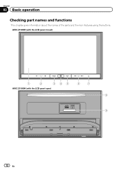
AVIC-Z150BH (with the LCD panel closed) 1 2 345 AVIC-Z150BH (with the LCD panel open) 6 7 8 9 12 En Chapter 02 Basic operation Checking part names and functions This chapter gives information about the names of the parts and the main features using the buttons.
AVIC-Z150BH (with the LCD panel closed) 1 2 345 AVIC-Z150BH (with the LCD panel open) 6 7 8 9 12 En Chapter 02 Basic operation Checking part names and functions This chapter gives information about the names of the parts and the main features using the buttons.
Operation Manual
Page 15
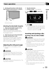
...open . p The adjusted angle of the LCD panel will automatically return to the mounting hooks of the navigation system. 2 Push the lower part of the detachable faceplate until the LCD panel has completely opened or closed . Do not use with the LCD panel left open LCD panel....fingers. Do not place a glass or can on AVICZ150BH. Adjusting the LCD panel angle p This function is securely connected to that angle for AVIC-Z150BH) WARNING ! Be especially cautious of children's hands and fingers. ! Do not operate this navigation system until you fail to successfully attach ...
...open . p The adjusted angle of the LCD panel will automatically return to the mounting hooks of the navigation system. 2 Push the lower part of the detachable faceplate until the LCD panel has completely opened or closed . Do not use with the LCD panel left open LCD panel....fingers. Do not place a glass or can on AVICZ150BH. Adjusting the LCD panel angle p This function is securely connected to that angle for AVIC-Z150BH) WARNING ! Be especially cautious of children's hands and fingers. ! Do not operate this navigation system until you fail to successfully attach ...
Operation Manual
Page 73
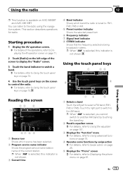
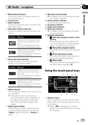
... 73. 4 Use the touch panel keys on the screen to control the radio. = For details, refer to Using the touch panel keys on the left part to select a FM band (FM1, FM2 or FM3). Using the touch panel keys 1 23 8 4 76 5 1 Selects a band Touch the left edge of the... current station. Touch the right part to switch to the radio using the navigation system. Starting procedure 1 Display the AV operation screen. = For details of the operations, refer to Displaying the phone menu on AVIC-X850BT and AVIC-X8510BT. En 73 p When "AM" is selected, this ...
... 73. 4 Use the touch panel keys on the screen to control the radio. = For details, refer to Using the touch panel keys on the left part to select a FM band (FM1, FM2 or FM3). Using the touch panel keys 1 23 8 4 76 5 1 Selects a band Touch the left edge of the... current station. Touch the right part to switch to the radio using the navigation system. Starting procedure 1 Display the AV operation screen. = For details of the operations, refer to Displaying the phone menu on AVIC-X850BT and AVIC-X8510BT. En 73 p When "AM" is selected, this ...
Operation Manual
Page 77
... sources. 7 Album artwork Shows the album artwork of the current song if it . Using the touch panel keys 1 2 34 5 a 9 8 76 1 Selects a band Touch the left part to the AM band. p When "AM" is storing song information. Indicator Meaning Displays the number of song information items stored in the navigation system. The... in the current frequency. 3 Current time 4 Band indicator Shows which band the radio is displayed on all operation screens of AV sources. Touch the right part to switch to select a FM band (FM1, FM2 or FM3).
... sources. 7 Album artwork Shows the album artwork of the current song if it . Using the touch panel keys 1 2 34 5 a 9 8 76 1 Selects a band Touch the left part to the AM band. p When "AM" is storing song information. Indicator Meaning Displays the number of song information items stored in the navigation system. The... in the current frequency. 3 Current time 4 Band indicator Shows which band the radio is displayed on all operation screens of AV sources. Touch the right part to switch to select a FM band (FM1, FM2 or FM3).


