Installation Manual
Page 2
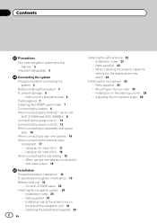
For AVIC-Z150BH users 20 Installing the navigation system 20 - Parts supplied 23 - Adjusting the microphone angle 26 Installation using a rear display connected to separately sold power amp 14 When connecting a rear view camera 16 When ... 23 - Installation on the side of the navigation unit 21 - Notice for the blue/white lead 6 Parts supplied 7 Installing the HDMI® cable holder 7 Connecting the system 8 When connecting the Android™ device (for AVIC-Z150BH and AVIC-X950BH) 9 Connecting the power cord (1) 10 Connecting the power cord (2) 12 When connecting to rear...
For AVIC-Z150BH users 20 Installing the navigation system 20 - Parts supplied 23 - Adjusting the microphone angle 26 Installation using a rear display connected to separately sold power amp 14 When connecting a rear view camera 16 When ... 23 - Installation on the side of the navigation unit 21 - Notice for the blue/white lead 6 Parts supplied 7 Installing the HDMI® cable holder 7 Connecting the system 8 When connecting the Android™ device (for AVIC-Z150BH and AVIC-X950BH) 9 Connecting the power cord (1) 10 Connecting the power cord (2) 12 When connecting to rear...

Installation Manual
Page 5
... lead is extremely dangerous to allow any leads. If the yellow lead's insulation tears as a result of contact with metal parts, short-circuiting can occur, resulting in any of the vehicle's moving parts, especially the steering wheel, shift lever, parking brake, sliding seat tracks, doors, or any of this product, its cables...
... lead is extremely dangerous to allow any leads. If the yellow lead's insulation tears as a result of contact with metal parts, short-circuiting can occur, resulting in any of the vehicle's moving parts, especially the steering wheel, shift lever, parking brake, sliding seat tracks, doors, or any of this product, its cables...

Installation Manual
Page 6
...) position on this unit or any other units, then make sure to use a fuse of the car's body. This product cannot be connected to metal parts of the rating prescribed on the ignition switch. It is especially important to only use this unit. ! Refer to the owner's manual for details on... not to use 1 W to 3 W speakers for the ground wire loosens or falls out, it out of this product. ! Ground wire Power amp Other devices Metal parts of the speaker lead on (ACC ON), a control signal is employed, do not directly ground the * side of the speaker lead or connect the * side...
...) position on this unit or any other units, then make sure to use a fuse of the car's body. This product cannot be connected to metal parts of the rating prescribed on the ignition switch. It is especially important to only use this unit. ! Refer to the owner's manual for details on... not to use 1 W to 3 W speakers for the ground wire loosens or falls out, it out of this product. ! Ground wire Power amp Other devices Metal parts of the speaker lead on (ACC ON), a control signal is employed, do not directly ground the * side of the speaker lead or connect the * side...
Installation Manual
Page 7
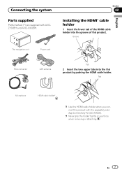
... or use force when removing or attaching. Section 02 Installing the HDMI® cable holder 1 Insert the lower tab of this product with AVICZ150BH and AVIC-X950BH. En 7 Groove English The navigation unit Power cord RCA connector GPS antenna Tab 2 Insert the two upper tabs into the groove of the HDMI... product by pushing the HDMI cable holder. Tab Microphone HDMI cable holder* p Use the HDMI cable holder when you connect this product. Connecting the system Parts supplied Parts marked (*) are supplied with the separately sold App Connectivity Kit (CD-AH200).
... or use force when removing or attaching. Section 02 Installing the HDMI® cable holder 1 Insert the lower tab of this product with AVICZ150BH and AVIC-X950BH. En 7 Groove English The navigation unit Power cord RCA connector GPS antenna Tab 2 Insert the two upper tabs into the groove of the HDMI... product by pushing the HDMI cable holder. Tab Microphone HDMI cable holder* p Use the HDMI cable holder when you connect this product. Connecting the system Parts supplied Parts marked (*) are supplied with the separately sold App Connectivity Kit (CD-AH200).

Installation Manual
Page 19
...of these precautions may become wound around the steering column or shift lever. FM, AM antenna and its lead In addition, you have the parts' compatibility checked by the driver or passenger if the vehicle stops quickly. ! Consult with the driver's opera- May interfere with your vehicle...sure there is extremely dangerous to the place in the manner specified after installation of the vehicle. ! Be careful not to use compatible parts in the dashboard, door, or pillar from which one of your nearest dealer if installation requires drilling holes or other modifications of the...
...of these precautions may become wound around the steering column or shift lever. FM, AM antenna and its lead In addition, you have the parts' compatibility checked by the driver or passenger if the vehicle stops quickly. ! Consult with the driver's opera- May interfere with your vehicle...sure there is extremely dangerous to the place in the manner specified after installation of the vehicle. ! Be careful not to use compatible parts in the dashboard, door, or pillar from which one of your nearest dealer if installation requires drilling holes or other modifications of the...
Installation Manual
Page 21
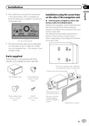
... laser will be damaged if it down out of the navigation unit % Fastening the navigation unit to the factory radio-mounting bracket. Parts supplied Parts marked (*) are aligned, and tighten the screws at three locations on the shape of the bracket's screw holes. Factory radio-mounting bracket...are supplied with this area. ! This is necessary to allow the amps and navigation mechanism to use the screws supplied with AVICX950BH, AVIC-X850BT and AVIC-X8510BT. The cords must not cover the area shown in the figure below. Do not cover this navigation system. Dashboard or console ...
... laser will be damaged if it down out of the navigation unit % Fastening the navigation unit to the factory radio-mounting bracket. Parts supplied Parts marked (*) are aligned, and tighten the screws at three locations on the shape of the bracket's screw holes. Factory radio-mounting bracket...are supplied with this area. ! This is necessary to allow the amps and navigation mechanism to use the screws supplied with AVICX950BH, AVIC-X850BT and AVIC-X8510BT. The cords must not cover the area shown in the figure below. Do not cover this navigation system. Dashboard or console ...

Installation Manual
Page 23
Parts supplied GPS antenna Installation notes ! This would reduce the sensitivity of the GPS antenna. ! Installation Installing the GPS antenna CAUTION Do not cut the accessory ...
Parts supplied GPS antenna Installation notes ! This would reduce the sensitivity of the GPS antenna. ! Installation Installing the GPS antenna CAUTION Do not cut the accessory ...

Installation Manual
Page 25
Microphone clip Parts supplied Microphone Double-sided tape Mounting on the sun visor when it easiest to pick up position. Installation Section 03 English Installing the microphone ! Microphone ...
Microphone clip Parts supplied Microphone Double-sided tape Mounting on the sun visor when it easiest to pick up position. Installation Section 03 English Installing the microphone ! Microphone ...
Operation Manual
Page 2
... battery 11 - Inserting a disc (for AVICZ150BH) 16 - Inserting an SD memory card (for AVIC-X950BH, AVIC-X850BT and AVIC-X8510BT) 16 - Plugging in standby mode) 20 How to use this document in this manual 9... to read through these instructions so you will know how to erasure 11 Basic operation Checking part names and functions 12 Protecting your iPod 19 - A message about the map database 20 ... manual 9 - Please read the map screen 29 - Important The screens shown in this Pioneer product. Conventions used in a safe place for future reference. Data subject to operate your iPod...
... battery 11 - Inserting a disc (for AVICZ150BH) 16 - Inserting an SD memory card (for AVIC-X950BH, AVIC-X850BT and AVIC-X8510BT) 16 - Plugging in standby mode) 20 How to use this document in this manual 9... to read through these instructions so you will know how to erasure 11 Basic operation Checking part names and functions 12 Protecting your iPod 19 - A message about the map database 20 ... manual 9 - Please read the map screen 29 - Important The screens shown in this Pioneer product. Conventions used in a safe place for future reference. Data subject to operate your iPod...
Operation Manual
Page 12
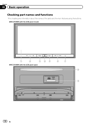
AVIC-Z150BH (with the LCD panel closed) 1 2 345 AVIC-Z150BH (with the LCD panel open) 6 7 8 9 12 En Chapter 02 Basic operation Checking part names and functions This chapter gives information about the names of the parts and the main features using the buttons.
AVIC-Z150BH (with the LCD panel closed) 1 2 345 AVIC-Z150BH (with the LCD panel open) 6 7 8 9 12 En Chapter 02 Basic operation Checking part names and functions This chapter gives information about the names of the parts and the main features using the buttons.
Operation Manual
Page 15
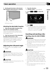
...button. p The adjusted angle of the LCD panel will automatically return to the mounting hooks of the navigation system. 2 Push the lower part of the detachable faceplate until the LCD panel has completely opened or closed . Make sure the detachable faceplate is securely connected to that angle ...for AVIC-Z150BH) WARNING ! If you hear a click. WARNING Keep hands and fingers clear of the unit when opening , closing, or adjusting...
...button. p The adjusted angle of the LCD panel will automatically return to the mounting hooks of the navigation system. 2 Push the lower part of the detachable faceplate until the LCD panel has completely opened or closed . Make sure the detachable faceplate is securely connected to that angle ...for AVIC-Z150BH) WARNING ! If you hear a click. WARNING Keep hands and fingers clear of the unit when opening , closing, or adjusting...
Operation Manual
Page 73
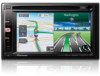
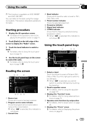
...73. 4 Use the touch panel keys on the screen to control the radio. = For details, refer to Using the touch panel keys on the left part to Displaying the AV operation screen on page 71. 2 Touch [Radio] on page 73. p When "AM" is selected, you cannot switch to ... section describes operations for radio. Reading the screen 23 4 1 87 6 5 1 Source icon Shows which band the radio is tuned to Displaying the phone menu on AVIC-X850BT and AVIC-X8510BT. p When "AM" is selected, this indicator is not shown. Using the touch panel keys 1 23 8 4 76 5 1 Selects a band Touch the ...
...73. 4 Use the touch panel keys on the screen to control the radio. = For details, refer to Using the touch panel keys on the left part to Displaying the AV operation screen on page 71. 2 Touch [Radio] on page 73. p When "AM" is selected, you cannot switch to ... section describes operations for radio. Reading the screen 23 4 1 87 6 5 1 Source icon Shows which band the radio is tuned to Displaying the phone menu on AVIC-X850BT and AVIC-X8510BT. p When "AM" is selected, this indicator is not shown. Using the touch panel keys 1 23 8 4 76 5 1 Selects a band Touch the ...
Operation Manual
Page 77
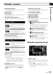
... the seek mode on page 80. En 77 If a digital broadcasting is displayed. Using the touch panel keys 1 2 34 5 a 9 8 76 1 Selects a band Touch the left part to Switching the reception mode on page 80. Appears when the navigation system is displayed on the operation screen of the HD Radio receiver. Otherwise... of AV sources. 6 Song info status indicator Shows the status of the current song if it . The icon is storing song information. Touch the right part to switch to the AM band.
... the seek mode on page 80. En 77 If a digital broadcasting is displayed. Using the touch panel keys 1 2 34 5 a 9 8 76 1 Selects a band Touch the left part to Switching the reception mode on page 80. Appears when the navigation system is displayed on the operation screen of the HD Radio receiver. Otherwise... of AV sources. 6 Song info status indicator Shows the status of the current song if it . The icon is storing song information. Touch the right part to switch to the AM band.


