Owner's Manual
Page 4
... functions Adjusting the response positions of the touch panels (Touch Panel Calibration) 75 Using an AUX source 75 Using an external unit 76 Installation Connecting the units 77 Installation 87 Additional information Troubleshooting 90 Error messages 92 Understanding auto EQ error messages 96 Understanding messages 96 Indicator list 97 Handling guidelines 99...
... functions Adjusting the response positions of the touch panels (Touch Panel Calibration) 75 Using an AUX source 75 Using an external unit 76 Installation Connecting the units 77 Installation 87 Additional information Troubleshooting 90 Error messages 92 Understanding auto EQ error messages 96 Understanding messages 96 Indicator list 97 Handling guidelines 99...
Owner's Manual
Page 5
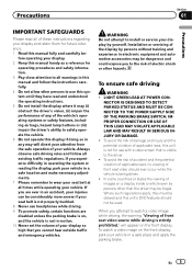
... your vehicle in any of applicable laws, this unit is not for future reference. 1 Read this manual fully and carefully be illegal. Installation or servicing of the display by yourself. To ensure safe driving WARNING ! If you are disabled unless the parking brake is on a display... , and the vehicle is strictly prohibited." Precautions Section 01 Precautions IMPORTANT SAFEGUARDS Please read and understood the operating instructions. 5 Do not install the display where it may be used. To avoid the risk of accident and the potential violation of applicable laws, no viewing of...
... your vehicle in any of applicable laws, this unit is not for future reference. 1 Read this manual fully and carefully be illegal. Installation or servicing of the display by yourself. To ensure safe driving WARNING ! If you are disabled unless the parking brake is on a display... , and the vehicle is strictly prohibited." Precautions Section 01 Precautions IMPORTANT SAFEGUARDS Please read and understood the operating instructions. 5 Do not install the display where it may be used. To avoid the risk of accident and the potential violation of applicable laws, no viewing of...
Owner's Manual
Page 6
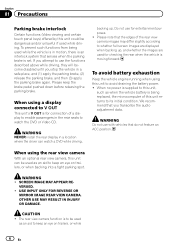
... up , and whether the images are used as an aid to its initial condition. Please keep an eye on trailers, or while 6 En WARNING NEVER install the rear display in a location where the driver can be dangerous and/or unlawful if used as when the vehicle battery is for connection of...
... up , and whether the images are used as an aid to its initial condition. Please keep an eye on trailers, or while 6 En WARNING NEVER install the rear display in a location where the driver can be dangerous and/or unlawful if used as when the vehicle battery is for connection of...
Owner's Manual
Page 7
...co-located or operated in accordance with any other antenna or transmitter. Information to which can radiate radio frequency energy and, if not installed and used in conjunction with the instructions, may cause undesired operation. However, there is subject to the following two conditions: (1) ... interference by one or more away from that interference will not occur in a residential installation. Before you start Section 02 Before you start FCC ID: AJDK044 MODEL NO.: AVH-P4400BH/AVH-P3400BH/ AVH-P2400BT IC: 775E-K044 This device complies with Part 15 of the FCC Rules. Note ...
...co-located or operated in accordance with any other antenna or transmitter. Information to which can radiate radio frequency energy and, if not installed and used in conjunction with the instructions, may cause undesired operation. However, there is subject to the following two conditions: (1) ... interference by one or more away from that interference will not occur in a residential installation. Before you start Section 02 Before you start FCC ID: AJDK044 MODEL NO.: AVH-P4400BH/AVH-P3400BH/ AVH-P2400BT IC: 775E-K044 This device complies with Part 15 of the FCC Rules. Note ...
Owner's Manual
Page 10
...remote control fall onto the floor, where it may become jammed under the brake or accelerator pedal. 10 En Batteries (battery pack or batteries installed) must not be swallowed, consult a doctor immediately. ! CAUTION ! Replace only with metallic tools. ! If the battery leaks, wipe the ...remote control completely clean and install a new battery. ! Important Failure to operate. ! When using for the first time, pull out the film protruding from the actual positions that...
...remote control fall onto the floor, where it may become jammed under the brake or accelerator pedal. 10 En Batteries (battery pack or batteries installed) must not be swallowed, consult a doctor immediately. ! CAUTION ! Replace only with metallic tools. ! If the battery leaks, wipe the ...remote control completely clean and install a new battery. ! Important Failure to operate. ! When using for the first time, pull out the film protruding from the actual positions that...
Owner's Manual
Page 30
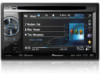
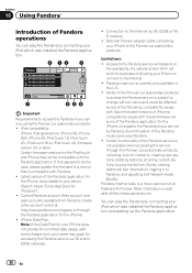
... service via 3G, EDGE or WiFi network. ! Pandora's service is available at http://www.pandora.com/register or through the Pioneer car audio/video products, including, but not limited to, creating new stations, deleting stations, emailing current stations, buying tracks from...by Pandora; Section 10 Using Pandoraâ Introduction of Pandora operations You can play the Pandora by connecting your iPod which was installed the Pandora application. 8 12 3 Pandora S.Rtrv Abcdeabcdeabcdeabcde Abcdeabcdeabcdeabcde Abcdeabcdeabcdeabcde Abcdeabcdeabcdeabcde Wed 28 May 12:45 PM 01:45 7 ...
... service via 3G, EDGE or WiFi network. ! Pandora's service is available at http://www.pandora.com/register or through the Pioneer car audio/video products, including, but not limited to, creating new stations, deleting stations, emailing current stations, buying tracks from...by Pandora; Section 10 Using Pandoraâ Introduction of Pandora operations You can play the Pandora by connecting your iPod which was installed the Pandora application. 8 12 3 Pandora S.Rtrv Abcdeabcdeabcdeabcde Abcdeabcdeabcdeabcde Abcdeabcdeabcdeabcde Abcdeabcdeabcdeabcde Wed 28 May 12:45 PM 01:45 7 ...
Owner's Manual
Page 31
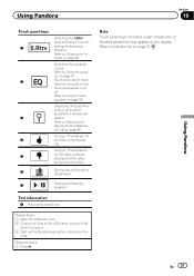
... Pandora operations may appear on page 48. Refer to Selecting and playing the QuickMix/station list on the display. Giving a "Thumbs-up the Pandora application installed on page 97. Refer to the next track. 6 Storing track information (Bookmark). 7 Pausing and starting playback. Playing tracks 1 Open the USB port cover. 2 Connect an...
... Pandora operations may appear on page 48. Refer to Selecting and playing the QuickMix/station list on the display. Giving a "Thumbs-up the Pandora application installed on page 97. Refer to the next track. 6 Storing track information (Bookmark). 7 Pausing and starting playback. Playing tracks 1 Open the USB port cover. 2 Connect an...
Owner's Manual
Page 67
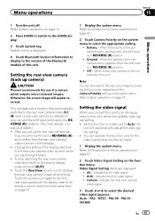
Menu operations Section 15 Menu operations 1 Turn the unit off . System menu is initially set up camera) CAUTION Pioneer recommends the use of this function only for the video signal input into the AV input. 1 Display the system menu. Setting the rear view camera (... off . Touch the source icon again to this unit Note You can operate this unit. Adjusts the AV video signal ! When a rear view camera is installed on the system menu to the rear view camera video by pressing the touch key, regardless of the connected lead is positive while the shift...
Menu operations Section 15 Menu operations 1 Turn the unit off . System menu is initially set up camera) CAUTION Pioneer recommends the use of this function only for the video signal input into the AV input. 1 Display the system menu. Setting the rear view camera (... off . Touch the source icon again to this unit Note You can operate this unit. Adjusts the AV video signal ! When a rear view camera is installed on the system menu to the rear view camera video by pressing the touch key, regardless of the connected lead is positive while the shift...
Owner's Manual
Page 75
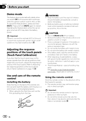
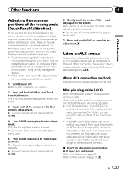
...Touch the screen gently for the adjusted position is saved. # Do not turn off the engine while the data is assigned to your local Pioneer dealer. 1 Turn the unit off the engine while the data is con- Data for the sound and video image to this unit. Refer ...on page 14. 2 Press and hold HOME. 4 Press HOME to complete 4-point adjustment. A portable audio/video player can connect auxiliary devices to Installation on this unit. About AUX connection methods You can be connected to complete the adjustment. Refer to this unit. There are two adjustment methods: 4-...
...Touch the screen gently for the adjusted position is saved. # Do not turn off the engine while the data is assigned to your local Pioneer dealer. 1 Turn the unit off the engine while the data is con- Data for the sound and video image to this unit. Refer ...on page 14. 2 Press and hold HOME. 4 Press HOME to complete 4-point adjustment. A portable audio/video player can connect auxiliary devices to Installation on this unit. About AUX connection methods You can be connected to complete the adjustment. Refer to this unit. There are two adjustment methods: 4-...
Owner's Manual
Page 77
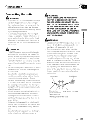
... sure to connect the ground wire first. In some countries or states the viewing of the display unit to the driver. ! Secure all installation and servicing of front seat video should not be in a location where they must be illegal. Take extra care in the car) En ...wire of the power amp and the one of electric shock or other hazards. CAUTION ! Installing or servicing the product may be connected to metal parts of smoke or malfunction. Do not use 1 W to authorized Pioneer service personnel. ! If the screw for this unit or power amp (sold commercially. ...
... sure to connect the ground wire first. In some countries or states the viewing of the display unit to the driver. ! Secure all installation and servicing of front seat video should not be in a location where they must be illegal. Take extra care in the car) En ...wire of the power amp and the one of electric shock or other hazards. CAUTION ! Installing or servicing the product may be connected to metal parts of smoke or malfunction. Do not use 1 W to authorized Pioneer service personnel. ! If the screw for this unit or power amp (sold commercially. ...
Owner's Manual
Page 78
... When this unit in a vehicle without ACC (accessory) position on , control signals are color-coded. To prevent a short-circuit, overheating or malfunction, be installed in order to share the power with metal parts to the engine compartment. - Wrap adhesive tape around wiring that comes into contact with other devices... cable to the battery by passing it to the power terminal of the auto antenna. Use a fuse of the battery before installation. - Never connect the blue/white cable to the antenna booster power supply terminal. ! Also, never connect it to ground. - Section 17...
... When this unit in a vehicle without ACC (accessory) position on , control signals are color-coded. To prevent a short-circuit, overheating or malfunction, be installed in order to share the power with metal parts to the engine compartment. - Wrap adhesive tape around wiring that comes into contact with other devices... cable to the battery by passing it to the power terminal of the auto antenna. Use a fuse of the battery before installation. - Never connect the blue/white cable to the antenna booster power supply terminal. ! Also, never connect it to ground. - Section 17...
Owner's Manual
Page 79
Installation Section 17 Installation En 79
Installation Section 17 Installation En 79
Owner's Manual
Page 80
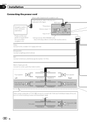
... controlled by ignition switch (12 V DC). Green Green/black Violet Violet/black Subwoofer (4 Ω) × 2 80 En Not used. Section 17 Installation Connecting the power cord 26 pin cable (Supplied with Violet and Violet/black leads of this unit. RGB input Navigation system (AVIC-U220(sold separately...)) Please contact your dealer to connect with auxiliary device. This product Antenna input Fuse (10 A) AUX jack (3.5 ø) (AVH-P4400BH only) Use a mini plug cable to inquire about the connectable navigation unit.
... controlled by ignition switch (12 V DC). Green Green/black Violet Violet/black Subwoofer (4 Ω) × 2 80 En Not used. Section 17 Installation Connecting the power cord 26 pin cable (Supplied with Violet and Violet/black leads of this unit. RGB input Navigation system (AVIC-U220(sold separately...)) Please contact your dealer to connect with auxiliary device. This product Antenna input Fuse (10 A) AUX jack (3.5 ø) (AVH-P4400BH only) Use a mini plug cable to inquire about the connectable navigation unit.
Owner's Manual
Page 81
...back lamp, connect the one in which the voltage changes when the gear shift is in .) Microphone (AVH-P4400BH/AVH-P3400BH/AVH-P2400BT only) Microphone input (AVH-P4400BH/AVH-P3400BH/AVH-P2400BT only) Wired remote input Hard-wired remote control adaptor can be connected to detect the ON/OFF status ...max. 300 mA 12 V DC). This connection enables the unit to system control terminal of this unit is moving forwards or backwards. Installation Section 17 Installation 4 m (13 ft. 1 in the REVERSE (R) position. Yellow/black If you use an equipment with needle-nosed pliers. The ...
...back lamp, connect the one in which the voltage changes when the gear shift is in .) Microphone (AVH-P4400BH/AVH-P3400BH/AVH-P2400BT only) Microphone input (AVH-P4400BH/AVH-P3400BH/AVH-P2400BT only) Wired remote input Hard-wired remote control adaptor can be connected to detect the ON/OFF status ...max. 300 mA 12 V DC). This connection enables the unit to system control terminal of this unit is moving forwards or backwards. Installation Section 17 Installation 4 m (13 ft. 1 in the REVERSE (R) position. Yellow/black If you use an equipment with needle-nosed pliers. The ...
Owner's Manual
Page 82
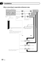
Section 17 Installation When connecting to separately sold power amp Rear output Front output Subwoofer output This product To rear output To front output To subwoofer output Power ...
Section 17 Installation When connecting to separately sold power amp Rear output Front output Subwoofer output This product To rear output To front output To subwoofer output Power ...
Owner's Manual
Page 83
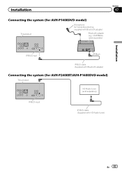
Installation Connecting the system (for AVH-P1400DVD model) This product Microphone for AVH-P2400BT/AVH-P1400DVD model) This product HD Radio tuner (sold separately) IP-BUS input IP-BUS cable (Supplied with Bluetooth adapter) Bluetooth adapter (e.g. CD-BTB200) (sold separately) Section 17 Installation IP-BUS input Black IP-BUS cable (Supplied with Bluetooth adapter) Connecting the system (for hands-free phoning (supplied with HD Radio tuner) En 83
Installation Connecting the system (for AVH-P1400DVD model) This product Microphone for AVH-P2400BT/AVH-P1400DVD model) This product HD Radio tuner (sold separately) IP-BUS input IP-BUS cable (Supplied with Bluetooth adapter) Bluetooth adapter (e.g. CD-BTB200) (sold separately) Section 17 Installation IP-BUS input Black IP-BUS cable (Supplied with Bluetooth adapter) Connecting the system (for hands-free phoning (supplied with HD Radio tuner) En 83
Owner's Manual
Page 84
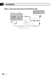
Section 17 Installation When connecting with optional CD-IU201V cable This product USB input iPod with video capabilities (sold separately) Dock connector AUX input (AUX) 1.5 m (4 ft. 11 in.) USB cable (Supplied with this unit for other models.) Interface cable (CD-IU201V) (sold separately) 2 m (6 ft. 7 in.) 84 En Sold separately for AVH-P4400BH.
Section 17 Installation When connecting with optional CD-IU201V cable This product USB input iPod with video capabilities (sold separately) Dock connector AUX input (AUX) 1.5 m (4 ft. 11 in.) USB cable (Supplied with this unit for other models.) Interface cable (CD-IU201V) (sold separately) 2 m (6 ft. 7 in.) 84 En Sold separately for AVH-P4400BH.
Owner's Manual
Page 85
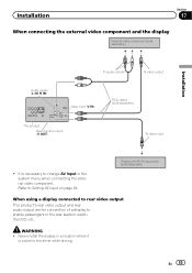
... is visible to change AV Input in the rear seats to Setting AV input on page 64. Installation Section 17 When connecting the external video component and the display External video component (sold separately) Installation Audio inputs (L IN, R IN) To audio outputs To video output Video input (V IN) RCA cables (sold separately...
... is visible to change AV Input in the rear seats to Setting AV input on page 64. Installation Section 17 When connecting the external video component and the display External video component (sold separately) Installation Audio inputs (L IN, R IN) To audio outputs To video output Video input (V IN) RCA cables (sold separately...
Owner's Manual
Page 86
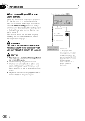
... view camera (sold separately) Violet/white Of the two lead wires connected to the back lamp, connect the one in the system menu. Section 17 Installation When connecting with a rear view camera When the shift lever is switched to REVERSE (R), the display on page 67. You need to set the Camera...
... view camera (sold separately) Violet/white Of the two lead wires connected to the back lamp, connect the one in the system menu. Section 17 Installation When connecting with a rear view camera When the shift lever is switched to REVERSE (R), the display on page 67. You need to set the Camera...
Owner's Manual
Page 87
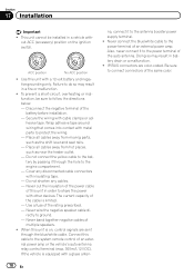
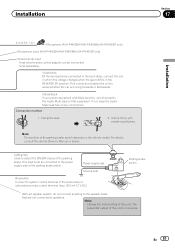
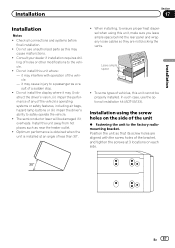
...'s ability to a passenger as a result of a sudden stop. ! In such case, use unauthorized parts as near the heater outlet. ! Installation using this unit cannot be damaged if it may cause injury to safely operate the vehicle. ! Position the unit so that its screw holes are...performance of any loose cables so they are aligned with operation of holes or other modifications to the factory radiomounting bracket. Consult your dealer if installation requires drilling of the vehicle. - it may cause malfunctions. ! Leave ample space 5 cm 5 cm 5cm ! En 87 Optimum performance...
...'s ability to a passenger as a result of a sudden stop. ! In such case, use unauthorized parts as near the heater outlet. ! Installation using this unit cannot be damaged if it may cause injury to safely operate the vehicle. ! Position the unit so that its screw holes are...performance of any loose cables so they are aligned with operation of holes or other modifications to the factory radiomounting bracket. Consult your dealer if installation requires drilling of the vehicle. - it may cause malfunctions. ! Leave ample space 5 cm 5 cm 5cm ! En 87 Optimum performance...


