
WVCU161C User Guide
Page 1
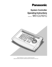
System Controller Operating Instructions Model No. WV-CU161C OPERATE SHIFT ALARM SUSRPEENSDET SCEATMUEPRA SETUP ALARM SLOW FUCNACMTIEORNA PROGRAM 7 HOME 1 2 4 5 6 8 9 3 AUTO B/W WIPPEARTROL STOP AUX 1 PPLAATYROL DEPAFTROL LEARN ESC 0 PRESET PPRREOSGERTSAEMT NEAR AUX 2 WIDE AUTO FOCUS FOCUS CLOSE IRIS IRIZSOOM RESET OPEN TELE FAR L System Controller WV-CU C UP R DOWN Before attempting to connect or operate this product, please read these instructions carefully and save this manual for future use.
System Controller Operating Instructions Model No. WV-CU161C OPERATE SHIFT ALARM SUSRPEENSDET SCEATMUEPRA SETUP ALARM SLOW FUCNACMTIEORNA PROGRAM 7 HOME 1 2 4 5 6 8 9 3 AUTO B/W WIPPEARTROL STOP AUX 1 PPLAATYROL DEPAFTROL LEARN ESC 0 PRESET PPRREOSGERTSAEMT NEAR AUX 2 WIDE AUTO FOCUS FOCUS CLOSE IRIS IRIZSOOM RESET OPEN TELE FAR L System Controller WV-CU C UP R DOWN Before attempting to connect or operate this product, please read these instructions carefully and save this manual for future use.
WVCU161C User Guide
Page 5
PREFACE The WV-CU161C System Controller is designed for one-to-one use with camera control functions. The controller can operate the pan/tilt head, lens and patrol play function from the controller in the connected Receiver. 5 You can transmit camera control commands via an RS-485 line or a coaxial cable. A... audio board is provided with a Combination Camera or WV-RC100/WV-RC150 Receiver that is installed in normal operations. FEATURES The WV-CU161C offers the following features when used with a combination camera. • Pan/tilt control: Manual Pan/Tilt Slow ON/OFF, Auto Panning ON...
PREFACE The WV-CU161C System Controller is designed for one-to-one use with camera control functions. The controller can operate the pan/tilt head, lens and patrol play function from the controller in the connected Receiver. 5 You can transmit camera control commands via an RS-485 line or a coaxial cable. A... audio board is provided with a Combination Camera or WV-RC100/WV-RC150 Receiver that is installed in normal operations. FEATURES The WV-CU161C offers the following features when used with a combination camera. • Pan/tilt control: Manual Pan/Tilt Slow ON/OFF, Auto Panning ON...
WVCU161C User Guide
Page 11
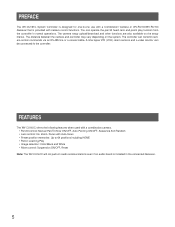
... be connected with a camera, a Time Lapse VCR and a video monitor as in the typical system configuration shown below. Combination Camera ALARM INPUT/OUTPUT (See page 14) WV-CU161C OPERATE ALARM System Controller WV-CU C SHIFT 1 2 AUTO 3 PATROL PLAY B/W UP ALARM RESET WIPER DEF SUSPEND 4 5 6 AUX1 AUX2 CAMERA SETUP SETUP 7 8 9 ...900 m or less (Using RG-59U, BELDEN 9259 or equivalent cable) (Coaxial Multiplex Communication) DATA COAX RS485 Control Site Video Monitor Note: Refer to the operating instructions of each system component for connection and operation. 11
... be connected with a camera, a Time Lapse VCR and a video monitor as in the typical system configuration shown below. Combination Camera ALARM INPUT/OUTPUT (See page 14) WV-CU161C OPERATE ALARM System Controller WV-CU C SHIFT 1 2 AUTO 3 PATROL PLAY B/W UP ALARM RESET WIPER DEF SUSPEND 4 5 6 AUX1 AUX2 CAMERA SETUP SETUP 7 8 9 ...900 m or less (Using RG-59U, BELDEN 9259 or equivalent cable) (Coaxial Multiplex Communication) DATA COAX RS485 Control Site Video Monitor Note: Refer to the operating instructions of each system component for connection and operation. 11
WVCU161C User Guide
Page 12
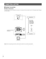
... to the operating instructions of the switcher. Camera Camera Housing Combination Camera Receiver Video Switcher System Controller WV-CU161C OPERATE ALARM System Controller WV-CU C SHIFT 1 2 AUTO 3 PATROL PLAY B/W UP ALARM RESET WIPER DEF SUSPEND 4 5 6 AUX1 AUX2 CAMERA SETUP SETUP 7 8 9 NEAR FAR L...VIDEO OUT Time Lapse VCR VIDEO IN VIDEO OUT DATA COAX RS485 Video Monitor Note: Refer to the nature of each system component for connection and operation. 12 q Connecting more Cameras A bi-directional video switcher purchased separately can be installed when ...
... to the operating instructions of the switcher. Camera Camera Housing Combination Camera Receiver Video Switcher System Controller WV-CU161C OPERATE ALARM System Controller WV-CU C SHIFT 1 2 AUTO 3 PATROL PLAY B/W UP ALARM RESET WIPER DEF SUSPEND 4 5 6 AUX1 AUX2 CAMERA SETUP SETUP 7 8 9 NEAR FAR L...VIDEO OUT Time Lapse VCR VIDEO IN VIDEO OUT DATA COAX RS485 Video Monitor Note: Refer to the nature of each system component for connection and operation. 12 q Connecting more Cameras A bi-directional video switcher purchased separately can be installed when ...

WVCU161C User Guide
Page 13
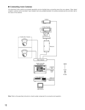
...public line is extended for the system operation. 13 An RS-485 is used when the communication line is busy, then it may cause instability for more than 1200 m (400 ft). Camera Site Control Site RS-485 Cable Coaxial Cable WV-CS854A Transmitter DATA PORT Network Interface...L FOCUS R PROGRAM RESET CAMERA FUNCTION HOME ESC PRESET 0 SET PROGRAM PRESET AUTO FOCUS WIDE TELE IRIS CLOSS OPEN IRIS RESET DOWN CAMERA IN VIDEO OUT System Controller WV-CU161C RS485 DATA T R TERM LINE G B A B A ON 4 COAX OFF 2 RS485 Video Monitor Video signal RS-485 signal Notes: • ...
...public line is extended for the system operation. 13 An RS-485 is used when the communication line is busy, then it may cause instability for more than 1200 m (400 ft). Camera Site Control Site RS-485 Cable Coaxial Cable WV-CS854A Transmitter DATA PORT Network Interface...L FOCUS R PROGRAM RESET CAMERA FUNCTION HOME ESC PRESET 0 SET PROGRAM PRESET AUTO FOCUS WIDE TELE IRIS CLOSS OPEN IRIS RESET DOWN CAMERA IN VIDEO OUT System Controller WV-CU161C RS485 DATA T R TERM LINE G B A B A ON 4 COAX OFF 2 RS485 Video Monitor Video signal RS-485 signal Notes: • ...

WVCU161C User Guide
Page 14
... Contact Alarm Indicator etc. +12 V s Cable-loss Compensation Setting The maximum allowable cable length between the time lapse VCR and the rear of the controller. Camera 14 A m (A ft) WV-CU161C Cable length (with a Time Lapse VCR Alarm in/out and recover-reset in the setup menu as a buzzer that exceeds 16 V DC 100...
... Contact Alarm Indicator etc. +12 V s Cable-loss Compensation Setting The maximum allowable cable length between the time lapse VCR and the rear of the controller. Camera 14 A m (A ft) WV-CU161C Cable length (with a Time Lapse VCR Alarm in/out and recover-reset in the setup menu as a buzzer that exceeds 16 V DC 100...
WVCU161C User Guide
Page 19
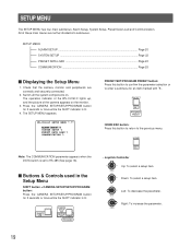
All of the camera appears on . WV-CU161C SETUP MENU *.** ALARM SETUP SYSTEM SETUP PRESET DATA LOAD COMMUNICATION Note: The COMMUNICATION parameter appears when the DATA switch is set to enter a submenu for an item marked with . Down: ... SHIFT indicator is lit. 4. HOME ESC • Joystick Controller L R DOWN UP L R Up: To select a setup item. SETUP MENU ALARM SETUP ...Page 20 SYSTEM SETUP ...Page 22 PRESET DATA LOAD Page 22 COMMUNICATION ...Page 25 s Displaying the Setup Menu 1. The operation indicator of the WV-CU161C lights up, and the picture of these main menus...
All of the camera appears on . WV-CU161C SETUP MENU *.** ALARM SETUP SYSTEM SETUP PRESET DATA LOAD COMMUNICATION Note: The COMMUNICATION parameter appears when the DATA switch is set to enter a submenu for an item marked with . Down: ... SHIFT indicator is lit. 4. HOME ESC • Joystick Controller L R DOWN UP L R Up: To select a setup item. SETUP MENU ALARM SETUP ...Page 20 SYSTEM SETUP ...Page 22 PRESET DATA LOAD Page 22 COMMUNICATION ...Page 25 s Displaying the Setup Menu 1. The operation indicator of the WV-CU161C lights up, and the picture of these main menus...
WVCU161C User Guide
Page 20
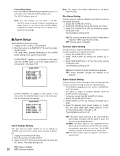
... or down. 3. s Alarm Setup Alarm related functions are not saved if the WVCU161C power is reset. Display the WV-CU161CC SETUP MENU. 2. ALARM TERMINAL appears on the monitor when an alarm is ...OFF: Alarm activation through the terminal is ON. Select ALARM OUTPUT by moving the joystick to the WV-CU161C SETUP MENU, complete the setup, and then turn the power off . • Closing Setup Menu... the joystick to connect with four sensors. Select the desired alarm output duration of the controller. ALARM SETUP ALARM DISPLAY ON SITE ALARM ON TERM.ALARM ON ALARM OUTPUT 10S ALARM ...
... or down. 3. s Alarm Setup Alarm related functions are not saved if the WVCU161C power is reset. Display the WV-CU161CC SETUP MENU. 2. ALARM TERMINAL appears on the monitor when an alarm is ...OFF: Alarm activation through the terminal is ON. Select ALARM OUTPUT by moving the joystick to the WV-CU161C SETUP MENU, complete the setup, and then turn the power off . • Closing Setup Menu... the joystick to connect with four sensors. Select the desired alarm output duration of the controller. ALARM SETUP ALARM DISPLAY ON SITE ALARM ON TERM.ALARM ON ALARM OUTPUT 10S ALARM ...

WVCU161C User Guide
Page 22
...: CAM6: CAM7: CAM8: P : Data saved. Select DOWN LOAD by the controller operation. A set of preset data can be given a title by moving the joystick to other cameras. 1. Display the SYSTEM SETUP menu. 2. Press the PRESET/SET/PROGRAM PRESET button. CAM1: DOWN LOAD ... s Preset Data Loading The data settings preset to the camera are downloaded to sound the switch buzzer when a button is s.) Downloading 1. Display the WV-CU161C SETUP MENU. 2. Display the SYSTEM SETUP menu. 2. Downloading starts. S: Less than 400 m (1 300 ft) M: 400 m (1 300 ft) to 700 m (2 300 ft) L: ...
...: CAM6: CAM7: CAM8: P : Data saved. Select DOWN LOAD by the controller operation. A set of preset data can be given a title by moving the joystick to other cameras. 1. Display the SYSTEM SETUP menu. 2. Press the PRESET/SET/PROGRAM PRESET button. CAM1: DOWN LOAD ... s Preset Data Loading The data settings preset to the camera are downloaded to sound the switch buzzer when a button is s.) Downloading 1. Display the WV-CU161C SETUP MENU. 2. Display the SYSTEM SETUP menu. 2. Downloading starts. S: Less than 400 m (1 300 ft) M: 400 m (1 300 ft) to 700 m (2 300 ft) L: ...

WVCU161C User Guide
Page 31
ALARM CONTROL FUNCTIONS When the WV-CU161C receives an alarm signal from a camera site, an alarm is multiplexed with video signals from the camera. The WV-CU161C can be continued even when an alarm is lit. RS-485 Site Communication Alarm is automatically reset after the programmed alarm output time has ... on the monitor. The alarm output signal is supplied to the time lapse VCR. The ALARM SUSPEND indicator lights up the camera or the WVCU161C. 1. Press the ALARM RESET/SUSPEND button to the preset position when an alarm is lit. If the preset number is on the rear panel...
ALARM CONTROL FUNCTIONS When the WV-CU161C receives an alarm signal from a camera site, an alarm is multiplexed with video signals from the camera. The WV-CU161C can be continued even when an alarm is lit. RS-485 Site Communication Alarm is automatically reset after the programmed alarm output time has ... on the monitor. The alarm output signal is supplied to the time lapse VCR. The ALARM SUSPEND indicator lights up the camera or the WVCU161C. 1. Press the ALARM RESET/SUSPEND button to the preset position when an alarm is lit. If the preset number is on the rear panel...

WVCU161C User Guide
Page 33
... SETUP SETUP PROGRAM AUTO B/W PATROL STOP [LEARNING] appears on the monitor. Follow the procedures described below to preset using the following controls so that it traces the routine course that is programmed for future recall. UP L R DOWN Adjust the picture using the joystick....set the camera patrol learning up the camera preset position while operating the combination camera. 1. Follow the procedures described below to the WV-CU161C SETUP MENU or camera SETUP MENU. 2. CAMERA SETUP SETUP PROGRAM PATROL PLAY PATROL LEARN [LEARNING] appears on the monitor. q...
... SETUP SETUP PROGRAM AUTO B/W PATROL STOP [LEARNING] appears on the monitor. Follow the procedures described below to preset using the following controls so that it traces the routine course that is programmed for future recall. UP L R DOWN Adjust the picture using the joystick....set the camera patrol learning up the camera preset position while operating the combination camera. 1. Follow the procedures described below to the WV-CU161C SETUP MENU or camera SETUP MENU. 2. CAMERA SETUP SETUP PROGRAM PATROL PLAY PATROL LEARN [LEARNING] appears on the monitor. q...
WVCU161C User Guide
Page 34
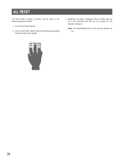
Note: The downloaded data for the Operate Indicator). Turn off (except for the camera remains as follows: 1. Turn on the Power Switch while simultaneously pressing numeric buttons 2, 4 and 6. 3. Resetting has been completed when all LEDs light up for a few seconds and then go off the Power Switch. 2. ALL RESET The WV-CU161C System Controller can be reset to the default settings as it is. 1 2 3 4 5 6 7 8 9 HOME ESC PRESET 0 SET PROGRAM PRESET 34
Note: The downloaded data for the Operate Indicator). Turn off (except for the camera remains as follows: 1. Turn on the Power Switch while simultaneously pressing numeric buttons 2, 4 and 6. 3. Resetting has been completed when all LEDs light up for a few seconds and then go off the Power Switch. 2. ALL RESET The WV-CU161C System Controller can be reset to the default settings as it is. 1 2 3 4 5 6 7 8 9 HOME ESC PRESET 0 SET PROGRAM PRESET 34


