

WVCU161C User Guide
Page 2
... not installed and used in the event of this equipment. Operation of theft. You should note the serial number of your purchase to aid identification in accordance with the instruction manual, may be required to rain or moisture. 2 WARNING: To reduce the risk of fire or electric shock, do not expose this book as a permanent record of this unit...
... not installed and used in the event of this equipment. Operation of theft. You should note the serial number of your purchase to aid identification in accordance with the instruction manual, may be required to rain or moisture. 2 WARNING: To reduce the risk of fire or electric shock, do not expose this book as a permanent record of this unit...

WVCU161C User Guide
Page 4
... s Cable-loss Compensation Setting ...14 s RS-485 Connection ...15 s Switch Setting ...16 SETUP MENU ...19 s Displaying the Setup Menu ...19 s Buttons & Controls used in Setup Menu ...19 s Alarm Setup ...20 s System Setup ...22 s Preset Data Loading ...22 s Communication Setup ...25 OPERATING PROCEDURES ...26 CAMERA CONTROL FUNCTIONS ...26 s Pan/Tilt Control ...26 s Lens Control ...26 s Operation of Combination Camera ...27 s Camera Housing Control ...30 s External Device Control ...30 ALARM CONTROL FUNCTIONS ...31 s Alarm Operation ...31 s Alarm Reset ...31 s Alarm Suspend ...31 CAMERA SETUP...
... s Cable-loss Compensation Setting ...14 s RS-485 Connection ...15 s Switch Setting ...16 SETUP MENU ...19 s Displaying the Setup Menu ...19 s Buttons & Controls used in Setup Menu ...19 s Alarm Setup ...20 s System Setup ...22 s Preset Data Loading ...22 s Communication Setup ...25 OPERATING PROCEDURES ...26 CAMERA CONTROL FUNCTIONS ...26 s Pan/Tilt Control ...26 s Lens Control ...26 s Operation of Combination Camera ...27 s Camera Housing Control ...30 s External Device Control ...30 ALARM CONTROL FUNCTIONS ...31 s Alarm Operation ...31 s Alarm Reset ...31 s Alarm Suspend ...31 CAMERA SETUP...
WVCU161C User Guide
Page 5
... with camera control functions. PREFACE The WV-CU161C System Controller is designed for one-to-one use with a Combination Camera or WV-RC100/WV-RC150 Receiver that is provided with Auto-focus • Preset position memories: Up to the controller. The camera setup upload/download and other functions are also available on the system. A time lapse VTR (VCR), alarm sensors and a video monitor can transmit camera control commands...
... with camera control functions. PREFACE The WV-CU161C System Controller is designed for one-to-one use with a Combination Camera or WV-RC100/WV-RC150 Receiver that is provided with Auto-focus • Preset position memories: Up to the controller. The camera setup upload/download and other functions are also available on the system. A time lapse VTR (VCR), alarm sensors and a video monitor can transmit camera control commands...

WVCU161C User Guide
Page 7
... 0 SET PROGRAM PRESET AUTO FOCUS WIDE TELE ZOOM IRIS CLOSE OPEN IRIS RESET DOWN u !2 !1 !0 o i q Operate Indicator (OPERATE) Lights up while the System Controller power is on the monitor. e Auto Panning/Black and White Selection/Patrol Stop Button (AUTO/B/W/PATROL STOP) AUTO: Pressing this button while holding down the CAMERA SETUP button will start to turn the indicator off. ton. PATROL STOP: Pressing this button will start the camera patrol play function. w Alarm Indicator (ALARM) Blinks when an alarm...
... 0 SET PROGRAM PRESET AUTO FOCUS WIDE TELE ZOOM IRIS CLOSE OPEN IRIS RESET DOWN u !2 !1 !0 o i q Operate Indicator (OPERATE) Lights up while the System Controller power is on the monitor. e Auto Panning/Black and White Selection/Patrol Stop Button (AUTO/B/W/PATROL STOP) AUTO: Pressing this button while holding down the CAMERA SETUP button will start to turn the indicator off. ton. PATROL STOP: Pressing this button will start the camera patrol play function. w Alarm Indicator (ALARM) Blinks when an alarm...
WVCU161C User Guide
Page 8
... is lit will turn on or off the AUX2 function controlling accessories that are connected to the camera or the specified receiver. When these buttons simultaneously for cameras provided with this function. The LED next to the button is lit while the alarm suspension mode operates. !5 Camera Setup/Setup/Program Button (CAMERA SETUP/SETUP/PROGRAM) Pressing this button for 2 seconds or more will open or close the Camera Setup menu. Pressing this button for 2 seconds or...
... is lit will turn on or off the AUX2 function controlling accessories that are connected to the camera or the specified receiver. When these buttons simultaneously for cameras provided with this function. The LED next to the button is lit while the alarm suspension mode operates. !5 Camera Setup/Setup/Program Button (CAMERA SETUP/SETUP/PROGRAM) Pressing this button for 2 seconds or more will open or close the Camera Setup menu. Pressing this button for 2 seconds or...

WVCU161C User Guide
Page 9
... position. This is to be used to turn the System Controller power on a coaxial cable or when using an RS-485 line. 9 u Video Output Connector (VIDEO OUT) This connector supplies composite video signals from the specified camera or a specified receiver. When the switch is in the table. o AC Cord !0 Power Switch (POWER) This switch is used when the controller needs to be isolated from the service outlet, or switch off . When the switch is set to page 14 for a long...
... position. This is to be used to turn the System Controller power on a coaxial cable or when using an RS-485 line. 9 u Video Output Connector (VIDEO OUT) This connector supplies composite video signals from the specified camera or a specified receiver. When the switch is in the table. o AC Cord !0 Power Switch (POWER) This switch is used when the controller needs to be isolated from the service outlet, or switch off . When the switch is set to page 14 for a long...
WVCU161C User Guide
Page 11
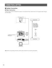
... the typical system configuration shown below. Combination Camera ALARM INPUT/OUTPUT (See page 14) WV-CU161C OPERATE ALARM System Controller WV-CU C SHIFT 1 2 AUTO 3 PATROL PLAY B/W UP ALARM RESET WIPER DEF SUSPEND 4 5 6 AUX1 AUX2 CAMERA SETUP SETUP 7 8 9 NEAR FAR L FOCUS R PROGRAM RESET CAMERA FUNCTION HOME ESC PRESET 0 SET PROGRAM PRESET AUTO FOCUS WIDE TELE IRIS CLOSS OPEN IRIS RESET DOWN CAMERA IN VIDEO OUT Time Lapse VCR VIDEO IN VIDEO OUT Camera Site 900 m or less (Using RG-59U...
... the typical system configuration shown below. Combination Camera ALARM INPUT/OUTPUT (See page 14) WV-CU161C OPERATE ALARM System Controller WV-CU C SHIFT 1 2 AUTO 3 PATROL PLAY B/W UP ALARM RESET WIPER DEF SUSPEND 4 5 6 AUX1 AUX2 CAMERA SETUP SETUP 7 8 9 NEAR FAR L FOCUS R PROGRAM RESET CAMERA FUNCTION HOME ESC PRESET 0 SET PROGRAM PRESET AUTO FOCUS WIDE TELE IRIS CLOSS OPEN IRIS RESET DOWN CAMERA IN VIDEO OUT Time Lapse VCR VIDEO IN VIDEO OUT Camera Site 900 m or less (Using RG-59U...
WVCU161C User Guide
Page 12
... L FOCUS R PROGRAM RESET CAMERA FUNCTION HOME ESC PRESET 0 SET PROGRAM PRESET AUTO FOCUS WIDE TELE IRIS CLOSS OPEN IRIS RESET DOWN CAMERA IN VIDEO OUT Time Lapse VCR VIDEO IN VIDEO OUT DATA COAX RS485 Video Monitor Note: Refer to the nature of each system component for connection and operation. 12 Video signal reception, camera control and alarm input reception are only available between the camera selected and the controller due to the operating instructions of the switcher.
... L FOCUS R PROGRAM RESET CAMERA FUNCTION HOME ESC PRESET 0 SET PROGRAM PRESET AUTO FOCUS WIDE TELE IRIS CLOSS OPEN IRIS RESET DOWN CAMERA IN VIDEO OUT Time Lapse VCR VIDEO IN VIDEO OUT DATA COAX RS485 Video Monitor Note: Refer to the nature of each system component for connection and operation. 12 Video signal reception, camera control and alarm input reception are only available between the camera selected and the controller due to the operating instructions of the switcher.

WVCU161C User Guide
Page 13
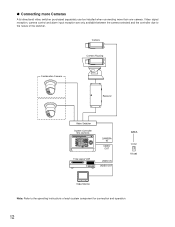
... Cable WV-CS854A Transmitter DATA PORT Network Interface Unit Receiver Public lines Network Interface Unit VIDEO OUT DATA PORT OPERATE ALARM System Controller WV-CU C SHIFT 1 2 AUTO 3 PATROL PAY B/W UP ALARM RESET SUSPEND WIPER DEF 4 5 6 AUX1 AUX2 CAMERA SETUP SERUP 7 8 9 NEAR FAR L FOCUS R PROGRAM RESET CAMERA FUNCTION HOME ESC PRESET 0 SET PROGRAM PRESET AUTO FOCUS WIDE TELE IRIS CLOSS OPEN IRIS RESET DOWN CAMERA IN VIDEO OUT System Controller WV-CU161C RS485 DATA T R TERM LINE G B A B A ON 4 COAX OFF 2 RS485 Video Monitor Video signal...
... Cable WV-CS854A Transmitter DATA PORT Network Interface Unit Receiver Public lines Network Interface Unit VIDEO OUT DATA PORT OPERATE ALARM System Controller WV-CU C SHIFT 1 2 AUTO 3 PATROL PAY B/W UP ALARM RESET SUSPEND WIPER DEF 4 5 6 AUX1 AUX2 CAMERA SETUP SERUP 7 8 9 NEAR FAR L FOCUS R PROGRAM RESET CAMERA FUNCTION HOME ESC PRESET 0 SET PROGRAM PRESET AUTO FOCUS WIDE TELE IRIS CLOSS OPEN IRIS RESET DOWN CAMERA IN VIDEO OUT System Controller WV-CU161C RS485 DATA T R TERM LINE G B A B A ON 4 COAX OFF 2 RS485 Video Monitor Video signal...

WVCU161C User Guide
Page 17
... bottom panel by removing the two screws. Recover Output Switch (SW1) 1. O.C: Open collector output, active when it is 16 V 500 mA maximum. The SW100 mounted inside the controller can be performed by qualified service personnel or system installers. • Unplug the controller power cord from the default settings. Place the bottom cover as described above. 2. q Internal Switch Setting Caution: • The internal switch setting should be seen.
... bottom panel by removing the two screws. Recover Output Switch (SW1) 1. O.C: Open collector output, active when it is 16 V 500 mA maximum. The SW100 mounted inside the controller can be performed by qualified service personnel or system installers. • Unplug the controller power cord from the default settings. Place the bottom cover as described above. 2. q Internal Switch Setting Caution: • The internal switch setting should be seen.
WVCU161C User Guide
Page 19
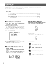
... of the camera appears on . The operation indicator of the WV-CU161C lights up, and the picture of these main menus are correctly and securely connected. 2. s Buttons & Controls used in the Setup Menu SHIFT button + CAMERA SETUP/SETUP/PROGRAM button: Press the CAMERA SETUP/SETUP/PROGRAM button for an item marked with . Switch all the system components on the monitor. 3. Down: To select a setup item. The SETUP MENU appears. PRESET SET PROGRAM PRESET HOME/ESC button: Press this button to...
... of the camera appears on . The operation indicator of the WV-CU161C lights up, and the picture of these main menus are correctly and securely connected. 2. s Buttons & Controls used in the Setup Menu SHIFT button + CAMERA SETUP/SETUP/PROGRAM button: Press the CAMERA SETUP/SETUP/PROGRAM button for an item marked with . Switch all the system components on the monitor. 3. Down: To select a setup item. The SETUP MENU appears. PRESET SET PROGRAM PRESET HOME/ESC button: Press this button to...
WVCU161C User Guide
Page 20
... (ALARM DISPLAY ON mode). • The alarm is reset. Note: The new settings are set up or down . 3. Move the cursor to ALARM DISPLAY. 3. The setup menu appears depending on the ALARM switch setting on the Alarm Output Setting. The initial factory setting is turned off before completing the setup. ON: The controller receives the site alarm (Video Motion Detection: VMD) issued by moving the joystick up or down. 3. EXT: The alarm signal continues to be output from the alarm output connector...
... (ALARM DISPLAY ON mode). • The alarm is reset. Note: The new settings are set up or down . 3. Move the cursor to ALARM DISPLAY. 3. The setup menu appears depending on the ALARM switch setting on the Alarm Output Setting. The initial factory setting is turned off before completing the setup. ON: The controller receives the site alarm (Video Motion Detection: VMD) issued by moving the joystick up or down. 3. EXT: The alarm signal continues to be output from the alarm output connector...

WVCU161C User Guide
Page 21
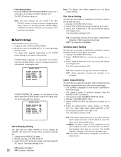
.../ESC button to return to select the desired preset numbers. Select ALARM TERMINAL by moving the joy- The ALARM TERMINAL menu opens. ALARM SETUP ALARM DISPLAY ON SITE ALARM ON TERM.ALARM ON ALARM OUTPUT 10S ALARM BUZZER ON ALARM PRESET - The camera will move its pan/tilt head to the position when the alarm operates. • The menu below appears when the ALARM switch on (4) alarm output setting. The initial factory setting is connected. 4. The initial factory setting...
.../ESC button to return to select the desired preset numbers. Select ALARM TERMINAL by moving the joy- The ALARM TERMINAL menu opens. ALARM SETUP ALARM DISPLAY ON SITE ALARM ON TERM.ALARM ON ALARM OUTPUT 10S ALARM BUZZER ON ALARM PRESET - The camera will move its pan/tilt head to the position when the alarm operates. • The menu below appears when the ALARM switch on (4) alarm output setting. The initial factory setting is connected. 4. The initial factory setting...

WVCU161C User Guide
Page 22
... right or left . Display the SYSTEM SETUP menu. 2. The initial factory setting is ON. Downloading starts. Select SYSTEM SETUP by the controller operation. A set of preset data can be given a title by moving the joystick up or down . 3. Select the ON or OFF mode by moving the joystick to CAM8 is pressed. 1. Press the PRESET/SET/PROGRAM PRESET button. s : No Data saved. (The factory default setting for all cameras from CAM1 to the...
... right or left . Display the SYSTEM SETUP menu. 2. The initial factory setting is ON. Downloading starts. Select SYSTEM SETUP by the controller operation. A set of preset data can be given a title by moving the joystick up or down . 3. Select the ON or OFF mode by moving the joystick to CAM8 is pressed. 1. Press the PRESET/SET/PROGRAM PRESET button. s : No Data saved. (The factory default setting for all cameras from CAM1 to the...

WVCU161C User Guide
Page 23
... data cannot be downloaded. • Downloading time is approximately 2 minutes per camera. Uploading 1. Press the PRESET/SET/PROGRAM PRESET button. The camera number and upload menu appear on the monitor as the WV-CS854 will move during downloading. CAM1: DOWN LOAD UP LOAD DATA TITLE 4. Uploading starts. CAM1: DOWN LOAD UP LOAD LOADING DATA TITLE END Blinking 6. The bar graph changing from s to fit the new settings. • The camera picture...
... data cannot be downloaded. • Downloading time is approximately 2 minutes per camera. Uploading 1. Press the PRESET/SET/PROGRAM PRESET button. The camera number and upload menu appear on the monitor as the WV-CS854 will move during downloading. CAM1: DOWN LOAD UP LOAD DATA TITLE 4. Uploading starts. CAM1: DOWN LOAD UP LOAD LOADING DATA TITLE END Blinking 6. The bar graph changing from s to fit the new settings. • The camera picture...

WVCU161C User Guide
Page 25
... moving the joystick up or down . 3. Data Bit This item lets you set the parity check mode for some functions such as resetting alarms. • This setting must be compatible with the peripherals connected. Display the COMMUNICATION menu. 2. Note: This setting must be operated if an address different from that set on the camera is OFF. Display the COMMUNICATION menu. 2. Select STOP BIT by moving the...
... moving the joystick up or down . 3. Data Bit This item lets you set the parity check mode for some functions such as resetting alarms. • This setting must be compatible with the peripherals connected. Display the COMMUNICATION menu. 2. Note: This setting must be operated if an address different from that set on the camera is OFF. Display the COMMUNICATION menu. 2. Select STOP BIT by moving the...
WVCU161C User Guide
Page 26
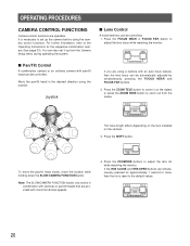
.../CAMERA FUNCTION button only works in the desired direction using the joystick. WIDE TELE ZOOM IRIS CLOSE OPEN IRIS RESET The focal length differs depending on the lens installed on the object or press the ZOOM WIDE button to adjust the lens focus while watching the monitor. If the IRIS CLOSE and IRIS OPEN buttons are using the camera control functions. OPERATING PROCEDURES CAMERA CONTROL FUNCTIONS Camera control...
.../CAMERA FUNCTION button only works in the desired direction using the joystick. WIDE TELE ZOOM IRIS CLOSE OPEN IRIS RESET The focal length differs depending on the lens installed on the object or press the ZOOM WIDE button to adjust the lens focus while watching the monitor. If the IRIS CLOSE and IRIS OPEN buttons are using the camera control functions. OPERATING PROCEDURES CAMERA CONTROL FUNCTIONS Camera control...

WVCU161C User Guide
Page 31
... reset mode in the Alarm On mode ALARM Character display (ALARM DISPLAY ON) The alarm indicator starts to blink and the buzzer sounds. (ALARM BUZZER is preset to the time lapse VCR until the alarm is activated. RS-485 Site Communication Alarm is generated. Light on the monitor screen when the alarm signal is supplied in this case is automatically reset after the programmed alarm output time has elapsed. The camera picture at the factory.) OPERATE ALARM Blinking: Alarm has been activated. q Automatic Reset...
... reset mode in the Alarm On mode ALARM Character display (ALARM DISPLAY ON) The alarm indicator starts to blink and the buzzer sounds. (ALARM BUZZER is preset to the time lapse VCR until the alarm is activated. RS-485 Site Communication Alarm is generated. Light on the monitor screen when the alarm signal is supplied in this case is automatically reset after the programmed alarm output time has elapsed. The camera picture at the factory.) OPERATE ALARM Blinking: Alarm has been activated. q Automatic Reset...

WVCU161C User Guide
Page 32
... System Controller, then all future setup operations must be performed using the same controller. • For further information, refer to the Operating Instructions for the selected camera. CAMERA SETUP SETUP PROGRAM (Example of Camera Setup menu) *** SET UP MENU *** PRESET 1* MAP HOME POSITION 15 SELF RETURN 10MIN AUTO MODE AUTO PAN AUTO PAN KEY SEQ DIGITAL FLIP OFF LOCAL/REMOTE LOCAL SPECIAL1 CAMERA RS485 SET UP 2. HOME ESC 5. Hold down the CAMERA SETUP/SETUP/PROGRAM button for the individual combination cameras. If camera setup is started using the WVCU161C...
... System Controller, then all future setup operations must be performed using the same controller. • For further information, refer to the Operating Instructions for the selected camera. CAMERA SETUP SETUP PROGRAM (Example of Camera Setup menu) *** SET UP MENU *** PRESET 1* MAP HOME POSITION 15 SELF RETURN 10MIN AUTO MODE AUTO PAN AUTO PAN KEY SEQ DIGITAL FLIP OFF LOCAL/REMOTE LOCAL SPECIAL1 CAMERA RS485 SET UP 2. HOME ESC 5. Hold down the CAMERA SETUP/SETUP/PROGRAM button for the individual combination cameras. If camera setup is started using the WVCU161C...

WVCU161C User Guide
Page 33
... the CAMERA SETUP/SETUP/PROGRAM button. UP L R DOWN Adjust the picture using the following controls so that it traces the routine course that is to the WV-CU161C SETUP MENU or camera SETUP MENU. 2. Refer to the manual included with the camera. 2. Press the PRESET/SET/PROGRAM PRESET button while holding down the PROGRAM button. The position and its number are memorized for 2 seconds will change the screen to operate the camera. LEARNING Note: Pressing the PROGRAM button...
... the CAMERA SETUP/SETUP/PROGRAM button. UP L R DOWN Adjust the picture using the following controls so that it traces the routine course that is to the WV-CU161C SETUP MENU or camera SETUP MENU. 2. Refer to the manual included with the camera. 2. Press the PRESET/SET/PROGRAM PRESET button while holding down the PROGRAM button. The position and its number are memorized for 2 seconds will change the screen to operate the camera. LEARNING Note: Pressing the PROGRAM button...


