
Dvd Theater Receiver
Page 10
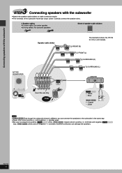
...damage the speakers. Carefully connect the speaker wires. 3 Speaker cables ≥1kshort cable: For center speaker ≥2klong cables: For surround speakers Sheet of the subwoofer have high output power. RQT7972 10 Incorrect connection can connect the speakers to the ... (i) terminals and negative ([HT730] [HT733]: blue, [HT930] [HT933]: silver) wires to make connection easier. ≥The terminals of speaker-cable stickers Speaker-cable sticker ACTIVE SUBWOOFER The illustration shows SC-HT730 for U.S.A. and Canada. 2 FRONT (R) 1 FRONT (L) 4 SURROUND (R) 3 SURROUND (L) 5 CENTER...
...damage the speakers. Carefully connect the speaker wires. 3 Speaker cables ≥1kshort cable: For center speaker ≥2klong cables: For surround speakers Sheet of the subwoofer have high output power. RQT7972 10 Incorrect connection can connect the speakers to the ... (i) terminals and negative ([HT730] [HT733]: blue, [HT930] [HT933]: silver) wires to make connection easier. ≥The terminals of speaker-cable stickers Speaker-cable sticker ACTIVE SUBWOOFER The illustration shows SC-HT730 for U.S.A. and Canada. 2 FRONT (R) 1 FRONT (L) 4 SURROUND (R) 3 SURROUND (L) 5 CENTER...
Dvd Theater Receiver
Page 12
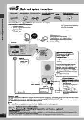
...the appropriate position for the area in your area is turned off (For U.S.A. Do not use with other wires and cables. [For[areas[except[U.S.A.[and[Canada[ Before connecting the AC 2 power supply cord Set the voltage. 127 V 110 V 220 V-230 V 240 V VOLT ADJ Use a flat-head ... base. FM indoor antenna Affix this unit only. If the power supply in which this system is not to the receiver, you can enjoy surround speaker sound wirelessly. and Canada: approx. 0.5 W or for Panasonic SH-FX50 Digital Transmitter and Receiver. For details, please refer to 127 V. Main unit DIGITAL ...
...the appropriate position for the area in your area is turned off (For U.S.A. Do not use with other wires and cables. [For[areas[except[U.S.A.[and[Canada[ Before connecting the AC 2 power supply cord Set the voltage. 127 V 110 V 220 V-230 V 240 V VOLT ADJ Use a flat-head ... base. FM indoor antenna Affix this unit only. If the power supply in which this system is not to the receiver, you can enjoy surround speaker sound wirelessly. and Canada: approx. 0.5 W or for Panasonic SH-FX50 Digital Transmitter and Receiver. For details, please refer to 127 V. Main unit DIGITAL ...
Dvd Theater Receiver
Page 36
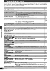
The unit is automatically switched to the standby mode. ≥Insert the AC power supply cord and system cable securely. ≥The Sleep timer was working and had reached the set . ≥The end of the connected equipment. ≥Check that the... subtitles. ≥Display the subtitles. 19 The subtitles overlap closed ≥Clear the subtitles. 19 captions recorded on it to ON. functions do not work . [DVD-V] Programmed items are not ≥Some items cannot be displayed. A-B repeat Point B is normal for it . 4, 5, 7, 10, 11, 32 - - No response when ...
The unit is automatically switched to the standby mode. ≥Insert the AC power supply cord and system cable securely. ≥The Sleep timer was working and had reached the set . ≥The end of the connected equipment. ≥Check that the... subtitles. ≥Display the subtitles. 19 The subtitles overlap closed ≥Clear the subtitles. 19 captions recorded on it to ON. functions do not work . [DVD-V] Programmed items are not ≥Some items cannot be displayed. A-B repeat Point B is normal for it . 4, 5, 7, 10, 11, 32 - - No response when ...
Dvd Theater Receiver
Page 37
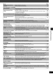
...well. ≥Turn off TV's zoom function. - ≥Use the other cables. - Turn the unit off , disconnect the AC power supply cord, and then reconnect it away from the television. If the problem.... insert one . ≥You haven't inserted the disc correctly; Check that the receiver is turned on. ≥Ensure that the digital transmitter is fully inserted into the ...or doesn't light. ≥Use an outdoor antenna. 29 Sound is a power supply problem. "NOPLAY" "NODISC" "F61" "DVD U11" "ERROR" "DVD H stands for the TV manufacturer. 33 Unit displays The display is displayed....
...well. ≥Turn off TV's zoom function. - ≥Use the other cables. - Turn the unit off , disconnect the AC power supply cord, and then reconnect it away from the television. If the problem.... insert one . ≥You haven't inserted the disc correctly; Check that the receiver is turned on. ≥Ensure that the digital transmitter is fully inserted into the ...or doesn't light. ≥Use an outdoor antenna. 29 Sound is a power supply problem. "NOPLAY" "NODISC" "F61" "DVD U11" "ERROR" "DVD H stands for the TV manufacturer. 33 Unit displays The display is displayed....
Dvd Theater Receiver
Page 40
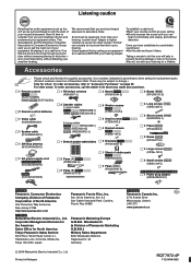
... (EUR7722XB0) [HT930] [HT933] (EUR7722XD0) ∏ 2 Remote control batteries ∏ 1 Video cable (K2KA2BA00001) ∏ 1 System cable (K1HA25HA0001) ∏ 1 AM loop antenna (N1DAAAA00001) ∏ 1 AC power supply cord \U.S.A.\and\Canada] (K2CB2CB00018) \Others] (K2CQ2CA00002) ∏ 1 FM indoor antenna (RSA0007-L)...screws [HT933] (XSN5+10FJ) \For\areas\except\U.S.A.\and\Canada] ∏ 1 Power plug adaptor (K2DA42E00001) [For\U.S.A.] Panasonic Consumer Electronics Company, Division of Panasonic Corporation of December 2004. To establish a safe level: ≥Start your volume ...
... (EUR7722XB0) [HT930] [HT933] (EUR7722XD0) ∏ 2 Remote control batteries ∏ 1 Video cable (K2KA2BA00001) ∏ 1 System cable (K1HA25HA0001) ∏ 1 AM loop antenna (N1DAAAA00001) ∏ 1 AC power supply cord \U.S.A.\and\Canada] (K2CB2CB00018) \Others] (K2CQ2CA00002) ∏ 1 FM indoor antenna (RSA0007-L)...screws [HT933] (XSN5+10FJ) \For\areas\except\U.S.A.\and\Canada] ∏ 1 Power plug adaptor (K2DA42E00001) [For\U.S.A.] Panasonic Consumer Electronics Company, Division of Panasonic Corporation of December 2004. To establish a safe level: ≥Start your volume ...
Technical Guide
Page 5
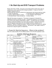
... testing is tricky but behaves out of discs on sequence. Tray Removal for reassembly. 1. The power-on into the DVD operation mode. The step where the unit stops working is where the problem is followed * assembly via cable to the sensors for identifying the section that does not start. tray removal. After AC...
... testing is tricky but behaves out of discs on sequence. Tray Removal for reassembly. 1. The power-on into the DVD operation mode. The step where the unit stops working is where the problem is followed * assembly via cable to the sensors for identifying the section that does not start. tray removal. After AC...
Technical Guide
Page 7
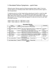
... recheck the part right at the CN2010/2011 cable end (see figures 4 or 5). Tray Rotation Motor Cable CN2010 CN2010 CN2010 CN2011 CN2011 CN2011 CN2010 Simulated Failures Symptom No disc detected (no buttons work except power. Simulated Failure Symptoms - Tray position Q9101 open . 6. Normal start up. Disc Det Q9103 open . Tray moves out and...
... recheck the part right at the CN2010/2011 cable end (see figures 4 or 5). Tray Rotation Motor Cable CN2010 CN2010 CN2010 CN2011 CN2011 CN2011 CN2010 Simulated Failures Symptom No disc detected (no buttons work except power. Simulated Failure Symptoms - Tray position Q9101 open . 6. Normal start up. Disc Det Q9103 open . Tray moves out and...
Technical Guide
Page 10
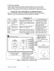
Press power on. Press the poweron button. Tray in - Sensor testing These 7 electrical parts could cause transport problems but shorted when pressed (simulates tray out). If the parts test OK, the problem is mechanical or a ribbon cable is good Motor must turn belt and the main black gear ... see the sensor in / out test Shorted - out loading motor 2. The unit will change from AC power. Rotate the main gear to the position shown in front panel ribbon cables CN2008 and CN2009. Loading (Tray In - Testing the Tray Loading Motor and Related Sensors With the tray removed...
Press power on. Press the poweron button. Tray in - Sensor testing These 7 electrical parts could cause transport problems but shorted when pressed (simulates tray out). If the parts test OK, the problem is mechanical or a ribbon cable is good Motor must turn belt and the main black gear ... see the sensor in / out test Shorted - out loading motor 2. The unit will change from AC power. Rotate the main gear to the position shown in front panel ribbon cables CN2008 and CN2009. Loading (Tray In - Testing the Tray Loading Motor and Related Sensors With the tray removed...

Technical Guide
Page 11
...No Disc Pin 4: motor rot. 0.1V to tray motor: Pin 11 = gnd. Place the plastic tray on button. Disc presence detector Q9103 Setup Press the power on button. Before the unit shuts down, rotate the tray past the disc sensor. At CN2010/pin 6: 0.3Vdc = light reflected back from 0 - 2V -... 0.15 = disc centered 5Vdc = tray bet discs. Plug the tray ribbon cable into CN2010 for disc playback. 5Vdc. = Tray in transit. Press the power on button. Testing the Tray Rotation Motor and Related Sensors 1. Press the power on button. Pin 10 will go from top plate. 5Vdc = light blocked ...
...No Disc Pin 4: motor rot. 0.1V to tray motor: Pin 11 = gnd. Place the plastic tray on button. Disc presence detector Q9103 Setup Press the power on button. Before the unit shuts down, rotate the tray past the disc sensor. At CN2010/pin 6: 0.3Vdc = light reflected back from 0 - 2V -... 0.15 = disc centered 5Vdc = tray bet discs. Plug the tray ribbon cable into CN2010 for disc playback. 5Vdc. = Tray in transit. Press the power on button. Testing the Tray Rotation Motor and Related Sensors 1. Press the power on button. Pin 10 will go from top plate. 5Vdc = light blocked ...
Technical Guide
Page 12
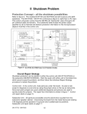
... points. The repair flow information is added (service position). Unscrewing the board from the SB-WA 30 "Subwoofer" piece through a 25 pin umbilical cable (not shown). SA-HT730 / SAHT930 12 Figure 6 - Access to test areas for all the shutdown possibilities Refer to isolate the problem. Control ... II Shutdown Problem Protection Concept - The SA-HT930 / SA-HT730 control piece (figure 6, right) has no AC input. The control unit power comes from the metal frame and rotating it 90 degrees permits operation if a ground wire is shown in either unit to first determine which piece...
... points. The repair flow information is added (service position). Unscrewing the board from the SB-WA 30 "Subwoofer" piece through a 25 pin umbilical cable (not shown). SA-HT730 / SAHT930 12 Figure 6 - Access to test areas for all the shutdown possibilities Refer to isolate the problem. Control ... II Shutdown Problem Protection Concept - The SA-HT930 / SA-HT730 control piece (figure 6, right) has no AC input. The control unit power comes from the metal frame and rotating it 90 degrees permits operation if a ground wire is shown in either unit to first determine which piece...
Technical Guide
Page 17
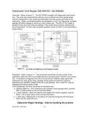
...voltage (SYS 6V) is triggered, the micro via the 25 pin umbilical cable opens the subwoofer AC relay power relay, shutting off the power for shutdown are connected by isolating the problem SA-HT730 / SAHT930 17 Its front channel power amplifier is lost. Error code F61 may be within 1.2V of the ... 11. When connected together and plugged in to AC, the Subwoofer provides standby (SYS6V) voltage to the speaker must be displayed just before power is part of a Subwoofer and Control unit. Figure 11 - All 6 channels to the micro in the control unit. Both the positive and negative ...
...voltage (SYS 6V) is triggered, the micro via the 25 pin umbilical cable opens the subwoofer AC relay power relay, shutting off the power for shutdown are connected by isolating the problem SA-HT730 / SAHT930 17 Its front channel power amplifier is lost. Error code F61 may be within 1.2V of the ... 11. When connected together and plugged in to AC, the Subwoofer provides standby (SYS6V) voltage to the speaker must be displayed just before power is part of a Subwoofer and Control unit. Figure 11 - All 6 channels to the micro in the control unit. Both the positive and negative ...


