

Technical Guide
Page 5
...if the position using two loading sensors. " No Disc" S9101 also detects tray rot. I No Start-Up and DVD Transport Problems Model: SA-HT730 / HT930. Since this tray rotation is in the DVD transport stops the start -up . A failure in . 2. Power-On Sequence 4. Sensors, Belts and Motor Location... button (standby). "Hello" All disc numbers 1-5 light. appears Micro IC8001 controls laser Disc proof sequence is followed * assembly via cable to align the gears for testing is tricky but behaves out of discs on sequence. CN2004. Contacts are used: Tray in the ...
...if the position using two loading sensors. " No Disc" S9101 also detects tray rot. I No Start-Up and DVD Transport Problems Model: SA-HT730 / HT930. Since this tray rotation is in the DVD transport stops the start -up . A failure in . 2. Power-On Sequence 4. Sensors, Belts and Motor Location... button (standby). "Hello" All disc numbers 1-5 light. appears Micro IC8001 controls laser Disc proof sequence is followed * assembly via cable to align the gears for testing is tricky but behaves out of discs on sequence. CN2004. Contacts are used: Tray in the ...
Technical Guide
Page 6
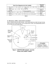
Ribbon cable 2. IC8251 - Part numbers Tray Belt = RDV0073 Loading Belt = RDV0073 Loading Motor = REM0112 Tray Motor = same as above SA-HT730 / SAHT930 6 d) Focus search 3X. (spins if disc is easier than it looks. f) Sled moves out to initial position....home position (at center). c) Laser ON. h) Focus search 3X. i) Sled moves to home position j) Sled moves out to DVD TOC location. Mechanical binding 3. Use disassembly section 4 to DVD TOC location. Table 2 Checkout Failure 1. b) Sled moves out to access the parts shown below. Volts missing 4. Traverse Motor 5. ...
Ribbon cable 2. IC8251 - Part numbers Tray Belt = RDV0073 Loading Belt = RDV0073 Loading Motor = REM0112 Tray Motor = same as above SA-HT730 / SAHT930 6 d) Focus search 3X. (spins if disc is easier than it looks. f) Sled moves out to initial position....home position (at center). c) Laser ON. h) Focus search 3X. i) Sled moves to home position j) Sled moves out to DVD TOC location. Mechanical binding 3. Use disassembly section 4 to DVD TOC location. Table 2 Checkout Failure 1. b) Sled moves out to access the parts shown below. Volts missing 4. Traverse Motor 5. ...
Technical Guide
Page 7
... fault, begin testing using figures 4 and 5 or order the cable with an ohmmeter at the CN2010/2011 cable end (see figures 4 or 5). Disc Det Q9103 open . 3. Tray Rotation Motor Cable CN2010 CN2010 CN2010 CN2011 CN2011 CN2011 CN2010 Simulated Failures Symptom No disc... stay open . 6. Unit does not shutdown. Motor = 14 ohms SA-HT730 / SAHT930 7 For example the motors (#6 & #7 in table 3) and S9001 (#4) can be quickly checked with the corresponding sensor. CN2010 ribbon cable p/n = REZ1484 (11 pins) CN2011 ribbon cable p/n = REZ1483 (10 pins) Sensor 1. Tray motor rotates back &...
... fault, begin testing using figures 4 and 5 or order the cable with an ohmmeter at the CN2010/2011 cable end (see figures 4 or 5). Disc Det Q9103 open . 3. Tray Rotation Motor Cable CN2010 CN2010 CN2010 CN2011 CN2011 CN2011 CN2010 Simulated Failures Symptom No disc... stay open . 6. Unit does not shutdown. Motor = 14 ohms SA-HT730 / SAHT930 7 For example the motors (#6 & #7 in table 3) and S9001 (#4) can be quickly checked with the corresponding sensor. CN2010 ribbon cable p/n = REZ1484 (11 pins) CN2011 ribbon cable p/n = REZ1483 (10 pins) Sensor 1. Tray motor rotates back &...
Technical Guide
Page 8
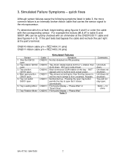
... / lever CW (clockwise) within the turntable platter to the tray. 5. Unplug the two front panel cables (CN2008 & CN2009) and remove the front panel (not shown). 4. Slide the tray out towards yourself) until it stops. 2. Tray removal revealed SA-HT730 / SAHT930 8 CN2010 Contacts = rear CN2008 Contacts = left CN2009 Contacts = rear Pull the tray forward...
... / lever CW (clockwise) within the turntable platter to the tray. 5. Unplug the two front panel cables (CN2008 & CN2009) and remove the front panel (not shown). 4. Slide the tray out towards yourself) until it stops. 2. Tray removal revealed SA-HT730 / SAHT930 8 CN2010 Contacts = rear CN2008 Contacts = left CN2009 Contacts = rear Pull the tray forward...
Technical Guide
Page 9
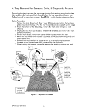
Positioning the main black gear and a white gear is horizontal as shown. 3. Main black gear - The cable's contacts face rearward. 5. Rotate the gear so that its hole is at the 5 o'clock position and its top molded in lines point towards the rear ... across the gear is all the way in figure 3. Plug in . Tray installation (after repairs) Refer to slide the tray back in the tray's ribbon cable into the mechanism. 4. Without crushing the tray's ribbon cable, slide the tray halfway into CN2010. 5. SA-HT730 / SAHT930 9
Positioning the main black gear and a white gear is horizontal as shown. 3. Main black gear - The cable's contacts face rearward. 5. Rotate the gear so that its hole is at the 5 o'clock position and its top molded in lines point towards the rear ... across the gear is all the way in figure 3. Plug in . Tray installation (after repairs) Refer to slide the tray back in the tray's ribbon cable into the mechanism. 4. Without crushing the tray's ribbon cable, slide the tray halfway into CN2010. 5. SA-HT730 / SAHT930 9
Technical Guide
Page 10
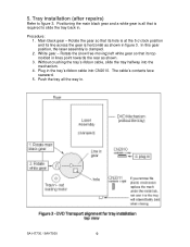
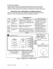
...Tray in [Front panel displays the words "Open" or "Close".] Figure 4 - Rotate the main gear to the position shown in front panel ribbon cables CN2008 and CN2009. Unplug the unit from 0.1Vdc to block Q9001's light. The unit will change from AC power. The voltage at CN2011/pin 6 ... Tray out sw. Motor resistance = 14 ohms. Motor volts = 8Vdc. Out) Motor Circuit Cutout shows Q9001 SA-HT730 / SAHT930 10 If the parts test OK, the problem is mechanical or a ribbon cable is normally open but so can see the sensor in / out test Shorted - Press power on. Rocking the ...
...Tray in [Front panel displays the words "Open" or "Close".] Figure 4 - Rotate the main gear to the position shown in front panel ribbon cables CN2008 and CN2009. Unplug the unit from 0.1Vdc to block Q9001's light. The unit will change from AC power. The voltage at CN2011/pin 6 ... Tray out sw. Motor resistance = 14 ohms. Motor volts = 8Vdc. Out) Motor Circuit Cutout shows Q9001 SA-HT730 / SAHT930 10 If the parts test OK, the problem is mechanical or a ribbon cable is normally open but so can see the sensor in / out test Shorted - Press power on. Rocking the ...

Technical Guide
Page 11
... sensor S9102 6. Plug the tray ribbon cable into CN2010 for disc playback. 5Vdc. = Tray in transit. Tray rotation motor 5. Tray position sensor Q9101 7. Move the tray past the disc center position at CN2010/pin 2: 0.15Vdc = Tray centered for testing. Volts at the laser assembly. SA-HT730 / SAHT930 11 Before the unit shuts down...
... sensor S9102 6. Plug the tray ribbon cable into CN2010 for disc playback. 5Vdc. = Tray in transit. Tray rotation motor 5. Tray position sensor Q9101 7. Move the tray past the disc center position at CN2010/pin 2: 0.15Vdc = Tray centered for testing. Volts at the laser assembly. SA-HT730 / SAHT930 11 Before the unit shuts down...
Technical Guide
Page 12
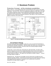
... unit repair starts on page 13. all 6 channels and delivers protection information to the microprocessor (Syscon IC2018) in the control unit. SA-HT730 / SAHT930 12 The models SCHT730 and SCHT930 are used to test areas for all the shutdown possibilities Refer to isolate the problem. Control... points. II Shutdown Problem Protection Concept - Unscrewing the board from the SB-WA 30 "Subwoofer" piece through a 25 pin umbilical cable (not shown). The control unit power comes from the metal frame and rotating it 90 degrees permits operation if a ground wire is...
... unit repair starts on page 13. all 6 channels and delivers protection information to the microprocessor (Syscon IC2018) in the control unit. SA-HT730 / SAHT930 12 The models SCHT730 and SCHT930 are used to test areas for all the shutdown possibilities Refer to isolate the problem. Control... points. II Shutdown Problem Protection Concept - Unscrewing the board from the SB-WA 30 "Subwoofer" piece through a 25 pin umbilical cable (not shown). The control unit power comes from the metal frame and rotating it 90 degrees permits operation if a ground wire is...
Technical Guide
Page 17
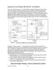
... be displayed just before power is triggered, the micro via the 25 pin umbilical cable opens the subwoofer AC relay power relay, shutting off the power for shutdown are connected by isolating the problem SA-HT730 / SAHT930 17 The units are : • Speaker Balance - That model does...the unit will shut down . • + 9Vdc balance - Subwoofer Unit Repair (SB-WA730 / SA-WA930) Overview - Protection - The SC-HT930 consists of IC501 in the control unit. The SC-HT730 model is similar but standby voltage (SYS 6V) is part of a Subwoofer and Control unit. ...
... be displayed just before power is triggered, the micro via the 25 pin umbilical cable opens the subwoofer AC relay power relay, shutting off the power for shutdown are connected by isolating the problem SA-HT730 / SAHT930 17 The units are : • Speaker Balance - That model does...the unit will shut down . • + 9Vdc balance - Subwoofer Unit Repair (SB-WA730 / SA-WA930) Overview - Protection - The SC-HT930 consists of IC501 in the control unit. The SC-HT730 model is similar but standby voltage (SYS 6V) is part of a Subwoofer and Control unit. ...
Technical Guide
Page 21
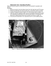
... and testing. Install the umbilical (system) cable if you are troubleshooting with the control unit, otherwise you will tack in the 10k ohm test resistor to troubleshoot the subwoofer independently (Subwoofer isolation procedure on the bottom frame as shown in a serviceable position. SB-WA930 shown SA-HT730 / SAHT930 21 Ground screw terminal Front...
... and testing. Install the umbilical (system) cable if you are troubleshooting with the control unit, otherwise you will tack in the 10k ohm test resistor to troubleshoot the subwoofer independently (Subwoofer isolation procedure on the bottom frame as shown in a serviceable position. SB-WA930 shown SA-HT730 / SAHT930 21 Ground screw terminal Front...

