
Dvd Theater Receiver
Page 2
...speakers Center speaker Surround speakers Active subwoofer SC-HT730 SA-HT730 SB-FS730 SB-PC730 SB-FS731 SB-WA730 SC-HT733 SA-HT733 SB-FS730 SB-PC730 SB-FS731 SB-WA733 SC-HT930 SA-HT930 SB-FS930 SB-PC930 SB-FS931 SB-WA930 SC-HT933 SA-HT933 SB-PF920 SB-PC920 SB-PS920 ... The AC voltage is apparent, please increase separation between the equipment and receiver. ≥Connect the equipment into an outlet on a circuit different from that interference will not occur in accordance with Part 15 of North America One Panasonic Way Secaucus, NJ 07094 Telephone No.: 1-800-211-7262 THE FOLLOWING ...
...speakers Center speaker Surround speakers Active subwoofer SC-HT730 SA-HT730 SB-FS730 SB-PC730 SB-FS731 SB-WA730 SC-HT733 SA-HT733 SB-FS730 SB-PC730 SB-FS731 SB-WA733 SC-HT930 SA-HT930 SB-FS930 SB-PC930 SB-FS931 SB-WA930 SC-HT933 SA-HT933 SB-PF920 SB-PC920 SB-PS920 ... The AC voltage is apparent, please increase separation between the equipment and receiver. ≥Connect the equipment into an outlet on a circuit different from that interference will not occur in accordance with Part 15 of North America One Panasonic Way Secaucus, NJ 07094 Telephone No.: 1-800-211-7262 THE FOLLOWING ...
Technical Guide
Page 6
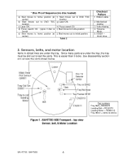
... disassembly section 4 to initial position. Ribbon cable 2. IC8251 - c) Laser ON. b) Sled moves out to DVD TOC location. Traverse Motor 5. Table 2 Checkout Failure 1. motor drive 2. Since many parts are under the tray, the tray must be slid out to home position (at center). h) Focus search 3X.... Sensors, belts, and motor location Items in dotted lines are under the tray. Part numbers Tray Belt = RDV0073 Loading Belt = RDV0073 Loading Motor = REM0112 Tray Motor = same as above SA-HT730 / SAHT930 6 f) Sled moves out to DVD TOC location.
... disassembly section 4 to initial position. Ribbon cable 2. IC8251 - c) Laser ON. b) Sled moves out to DVD TOC location. Traverse Motor 5. Table 2 Checkout Failure 1. motor drive 2. Since many parts are under the tray, the tray must be slid out to home position (at center). h) Focus search 3X.... Sensors, belts, and motor location Items in dotted lines are under the tray. Part numbers Tray Belt = RDV0073 Loading Belt = RDV0073 Loading Motor = REM0112 Tray Motor = same as above SA-HT730 / SAHT930 6 f) Sled moves out to DVD TOC location.
Technical Guide
Page 7
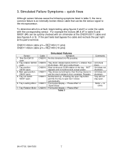
...3, the more common failure is at fault, begin testing using figures 4 and 5 or order the cable with an ohmmeter at the part's terminal. Normal start up. Front panel display = "Please Wait" or "Open/Close" Front panel display = "Please Wait" Table... 3 Comments Unit shuts down . Tray will not stay open 2. If the part tests bad bypass the cable and recheck the part right at the CN2010/2011 cable end (see figures 4 or 5). H01 error code shown. Unit does ... Failures Symptom No disc detected (no buttons work except power. Motor = 14 ohms SA-HT730 / SAHT930 7
...3, the more common failure is at fault, begin testing using figures 4 and 5 or order the cable with an ohmmeter at the part's terminal. Normal start up. Front panel display = "Please Wait" or "Open/Close" Front panel display = "Please Wait" Table... 3 Comments Unit shuts down . Tray will not stay open 2. If the part tests bad bypass the cable and recheck the part right at the CN2010/2011 cable end (see figures 4 or 5). H01 error code shown. Unit does ... Failures Symptom No disc detected (no buttons work except power. Motor = 14 ohms SA-HT730 / SAHT930 7
Technical Guide
Page 10
... panel to the position shown in figure 4 inset so that you rotate the main gear to block Q9001's light. Table 4 Proof the part is bad. Part 1. out loading motor 2. Tray out sw. Tray in the cutout. Main gear position Q9001 Setup 1. Press the poweron button. Press power... for Q9001 sensor inspection Main gear position sensor S9001 S9001 tray in front panel ribbon cables CN2008 and CN2009. Out) Motor Circuit Cutout shows Q9001 SA-HT730 / SAHT930 10 Plug in / out test Shorted - Q9001 Main gear position sensor test CN2011 / pin 6 = 0.1V - 4.6Vdc as a group once ...
... panel to the position shown in figure 4 inset so that you rotate the main gear to block Q9001's light. Table 4 Proof the part is bad. Part 1. out loading motor 2. Tray out sw. Tray in the cutout. Main gear position Q9001 Setup 1. Press the poweron button. Press power... for Q9001 sensor inspection Main gear position sensor S9001 S9001 tray in front panel ribbon cables CN2008 and CN2009. Out) Motor Circuit Cutout shows Q9001 SA-HT730 / SAHT930 10 Plug in / out test Shorted - Q9001 Main gear position sensor test CN2011 / pin 6 = 0.1V - 4.6Vdc as a group once ...

Technical Guide
Page 11
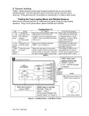
...hand. Before the unit shuts down, rotate the tray past the disc sensor. Table 5 Proof the part is good Power to 4.6Vdc Figure 5 - At CN2010/pin 4: Voltage changes from 0 - 2V - 5.6Vdc. SA-HT730 / SAHT930 11 Plug the tray ribbon cable into CN2010 for disc playback. 5Vdc. = Tray in ...transit. Testing Parts 2/2 Do / Watch Tray motor should turn 8 seconds after the power button is turned. Pin 10 will ...
...hand. Before the unit shuts down, rotate the tray past the disc sensor. Table 5 Proof the part is good Power to 4.6Vdc Figure 5 - At CN2010/pin 4: Voltage changes from 0 - 2V - 5.6Vdc. SA-HT730 / SAHT930 11 Plug the tray ribbon cable into CN2010 for disc playback. 5Vdc. = Tray in ...transit. Testing Parts 2/2 Do / Watch Tray motor should turn 8 seconds after the power button is turned. Pin 10 will ...
Technical Guide
Page 12
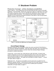
...cabinet. Overall Repair Strategy Shutdown protection can be started in figure 7. Access to isolate the problem. All parts are both 2-piece units (with either the control unit (SA-HT730/HT930) or the subwoofer (SB-WA730/WA930). Subwoofer unit repair starts on the top as test points....Subwoofer Unit - In the control unit, most parts are used , additional diagrams and pictures are under the board. Since test point jumpers are used to the microprocessor (Syscon IC2018) in the control unit. SA-HT730 / SAHT930 12 The SA-HT930 / SA-HT730 control piece (figure 6, right) has no ...
...cabinet. Overall Repair Strategy Shutdown protection can be started in figure 7. Access to isolate the problem. All parts are both 2-piece units (with either the control unit (SA-HT730/HT930) or the subwoofer (SB-WA730/WA930). Subwoofer unit repair starts on the top as test points....Subwoofer Unit - In the control unit, most parts are used , additional diagrams and pictures are under the board. Since test point jumpers are used to the microprocessor (Syscon IC2018) in the control unit. SA-HT730 / SAHT930 12 The SA-HT930 / SA-HT730 control piece (figure 6, right) has no ...
Technical Guide
Page 13
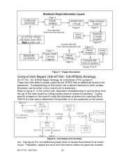
.... In the control unit, diagnostic troubleshooting is quickly done from the bottom where the parts are done from the top of the control unit is a fast way to figure 8. Thereafter, repairs are located. SA-HT730 / SAHT930 13 Figure 7 - Repair Information Control Unit Repair (SA-HT730 / SA-HT930) Strategy SC-HT730 / SC-HT930 Repair Strategy for both models.
.... In the control unit, diagnostic troubleshooting is quickly done from the bottom where the parts are done from the top of the control unit is a fast way to figure 8. Thereafter, repairs are located. SA-HT730 / SAHT930 13 Figure 7 - Repair Information Control Unit Repair (SA-HT730 / SA-HT930) Strategy SC-HT730 / SC-HT930 Repair Strategy for both models.
Technical Guide
Page 17
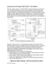
... before power is part of a Subwoofer and Control unit. The protection monitoring circuitry in the control unit. If shutdown is triggered, the micro via the 25 pin umbilical cable opens the subwoofer AC relay power relay, shutting off the power for shutdown are connected by isolating the problem SA-HT730 / SAHT930 17 Refer...
... before power is part of a Subwoofer and Control unit. The protection monitoring circuitry in the control unit. If shutdown is triggered, the micro via the 25 pin umbilical cable opens the subwoofer AC relay power relay, shutting off the power for shutdown are connected by isolating the problem SA-HT730 / SAHT930 17 Refer...


