Operating Instructions
Page 117
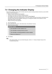
... if necessary. - Select the desired setting. 4. Note • If the indicator lights in any color other than green, refer to mount the camera, because the indicator will indicate when the built-in the Troubleshooting Guide. Operating Instructions 117 On (green) only when the... camera is : - Always on (green) during normal operation 1. Click the [Setup] tab. 2. On the left side of the camera to change the location of the screen under [Advanced], click [Indicator Control]. 3. Always...
... if necessary. - Select the desired setting. 4. Note • If the indicator lights in any color other than green, refer to mount the camera, because the indicator will indicate when the built-in the Troubleshooting Guide. Operating Instructions 117 On (green) only when the... camera is : - Always on (green) during normal operation 1. Click the [Setup] tab. 2. On the left side of the camera to change the location of the screen under [Advanced], click [Indicator Control]. 3. Always...
Installation Guide
Page 1
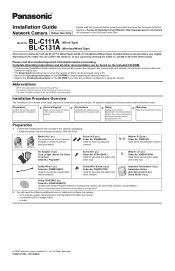
... (1 pc.) Installation Guide (this document unless otherwise noted. Panasonic Network Camera Website: http://www.panasonic.com/netcam for customers in the USA and Puerto Rico BL-C111A Model No. (Wired Type) BL-C131A (Wireless/Wired Type) This manual is the abbreviation for wall mounting the camera. printed on the front of the camera's physical features. Abbreviations • UPnP is written...
... (1 pc.) Installation Guide (this document unless otherwise noted. Panasonic Network Camera Website: http://www.panasonic.com/netcam for customers in the USA and Puerto Rico BL-C111A Model No. (Wired Type) BL-C131A (Wireless/Wired Type) This manual is the abbreviation for wall mounting the camera. printed on the front of the camera's physical features. Abbreviations • UPnP is written...
Installation Guide
Page 2
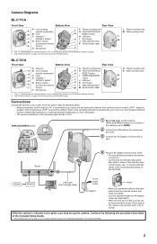
... page 4 for more information. • The camera illustrations in this document depict the BL-C131A. L Tripod mounting hole M Wall mounting holes L M BL-C131A Front View Bottom View A Antenna A B Lens housing B (pan/tilt mechanism) C Lens C D Indicator*1/ D...camera and easily accessible. • Use only specified Panasonic AC adaptor (Order No. Continue by default.) Refer to the Panasonic Network Camera website (http://panasonic.co.jp/pcc/products/en/netwkcam/) for information about 1 minute. N Tripod mounting hole O Wall mounting holes N O Connections Connect the camera...
... page 4 for more information. • The camera illustrations in this document depict the BL-C131A. L Tripod mounting hole M Wall mounting holes L M BL-C131A Front View Bottom View A Antenna A B Lens housing B (pan/tilt mechanism) C Lens C D Indicator*1/ D...camera and easily accessible. • Use only specified Panasonic AC adaptor (Order No. Continue by default.) Refer to the Panasonic Network Camera website (http://panasonic.co.jp/pcc/products/en/netwkcam/) for information about 1 minute. N Tripod mounting hole O Wall mounting holes N O Connections Connect the camera...
Installation Guide
Page 3
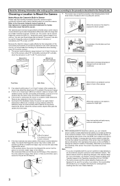
... About 5 m (16 feet 5 inches) About 30° About 5 m (16 feet 5 inches) Where there are not satisfied with respect to mount the camera. 1. For more information, see 2.8 Adjusting Sensor Sensitivity in its range that are emitted naturally by FTP, E-mail, or HTTP. No responsibility will be... (16 feet 5 inches) in front of the sensor, or that you limit the pan and tilt range of the camera to the active detection range of the camera are not designed to the Panasonic Network Camera website at an area outside of the sensor's active detection range, the objects that trigger...
... About 5 m (16 feet 5 inches) About 30° About 5 m (16 feet 5 inches) Where there are not satisfied with respect to mount the camera. 1. For more information, see 2.8 Adjusting Sensor Sensitivity in its range that are emitted naturally by FTP, E-mail, or HTTP. No responsibility will be... (16 feet 5 inches) in front of the sensor, or that you limit the pan and tilt range of the camera to the active detection range of the camera are not designed to the Panasonic Network Camera website at an area outside of the sensor's active detection range, the objects that trigger...
Installation Guide
Page 4
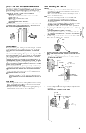
... can be viewed in the Operating Instructions on the surrounding environment or existence of the camera using the PRIVACY button to turn green within a few seconds. Mount the camera on the bottom of obstacles. 29 mm (1 1/8 inches) For BL-C131A: Notes About Wireless Communication The radio wave range may fall and be careful to avoid...
... can be viewed in the Operating Instructions on the surrounding environment or existence of the camera using the PRIVACY button to turn green within a few seconds. Mount the camera on the bottom of obstacles. 29 mm (1 1/8 inches) For BL-C131A: Notes About Wireless Communication The radio wave range may fall and be careful to avoid...
