Installation Guide
Page 1
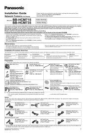
...; This document (Installation Guide) explains how to physically connect the camera to the power supply and network, as the camera's documentation.* *See the included Important Information for the connector cover) Order No. BB-HCM715A, BB-HCM715CE, BB-HCM735A, BB-HCM735CE Please read this document) (1 pc.) Setup Guide (1 pc.) Stand-alone SD Memory Card Recording Guide (1 pc.) Sunshade (1pc.) [BB-HCM735 Only] Order No. Installation Procedure Overview The following additional items to the Operating Instructions on the model...
...; This document (Installation Guide) explains how to physically connect the camera to the power supply and network, as the camera's documentation.* *See the included Important Information for the connector cover) Order No. BB-HCM715A, BB-HCM715CE, BB-HCM735A, BB-HCM735CE Please read this document) (1 pc.) Setup Guide (1 pc.) Stand-alone SD Memory Card Recording Guide (1 pc.) Sunshade (1pc.) [BB-HCM735 Only] Order No. Installation Procedure Overview The following additional items to the Operating Instructions on the model...
Installation Guide
Page 2
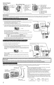
... number and MAC address label L AC adaptor cord/video cable hook M Speaker/microphone cable hook N LAN port O DC IN P External I hole Rear View J K L M N OPQRS *1 See 1.1 Understanding the Camera Indicator in the Troubleshooting Guide on the CD-ROM. Connect a LAN cable to the camera and to the PoE hub. • Your PoE hub must be connected to this input terminal. If the indicator does not light green, see 1.2.11 Audio Features in the Troubleshooting Guide...
... number and MAC address label L AC adaptor cord/video cable hook M Speaker/microphone cable hook N LAN port O DC IN P External I hole Rear View J K L M N OPQRS *1 See 1.1 Understanding the Camera Indicator in the Troubleshooting Guide on the CD-ROM. Connect a LAN cable to the camera and to the PoE hub. • Your PoE hub must be connected to this input terminal. If the indicator does not light green, see 1.2.11 Audio Features in the Troubleshooting Guide...
Installation Guide
Page 3
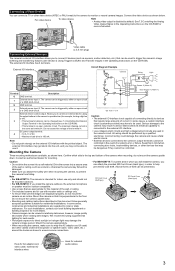
... V DC • Maximum load drive is an open circuit or a GND short-circuit. Confirm which you will install the camera, you to help prevent SD card theft. (Not all forms of the wall or ceiling. • The included screws are used to trigger the camera's image buffering and transferring features (see 7.4 Controlling the External Output Terminal in the Operating Instructions on the CD-ROM...
... V DC • Maximum load drive is an open circuit or a GND short-circuit. Confirm which you will install the camera, you to help prevent SD card theft. (Not all forms of the wall or ceiling. • The included screws are used to trigger the camera's image buffering and transferring features (see 7.4 Controlling the External Output Terminal in the Operating Instructions on the CD-ROM...
Installation Guide
Page 4
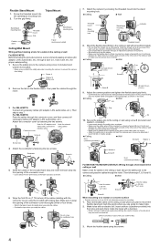
...L Washer L Screw B Duct (customer-provided) For BB-HCM715 (INDOOR USE ONLY): Wiring through the connector cover, and then connect all necessary cables (AC adaptor, LAN, audio/video, etc.). Attach the sunshade by fastening the two screws. Adjust the camera position and tighten the flexible stand grip firmly. • Confirm... to make holes. 2. Then pass the cables through a duct (i.e., hose, tube, etc.) for the type of the connector cover thoroughly (three or four times). • Stretch the tape to twice its length when you wrap the cables. • Overlap the...
...L Washer L Screw B Duct (customer-provided) For BB-HCM715 (INDOOR USE ONLY): Wiring through the connector cover, and then connect all necessary cables (AC adaptor, LAN, audio/video, etc.). Attach the sunshade by fastening the two screws. Adjust the camera position and tighten the flexible stand grip firmly. • Confirm... to make holes. 2. Then pass the cables through a duct (i.e., hose, tube, etc.) for the type of the connector cover thoroughly (three or four times). • Stretch the tape to twice its length when you wrap the cables. • Overlap the...


