
AJHD1700 User Guide
Page 5
... the recording/playback format and sync signals which support the operation mode 105 O Menu management accompanying switching the system frequency 106 Time code and user's bit 111 O Time code 111 O User's bit 111 O Setting the internal time code 111 O Setting the external time code 112 O Cue time registration, preroll and cue-up (These functions work only on the HOME, PF1 and PF2 screens 112 O Time code and user's bit playback 112 Superimpose screen 113 Selecting the audio recording channels and monitor output 114 Display saving...
... the recording/playback format and sync signals which support the operation mode 105 O Menu management accompanying switching the system frequency 106 Time code and user's bit 111 O Time code 111 O User's bit 111 O Setting the internal time code 111 O Setting the external time code 112 O Cue time registration, preroll and cue-up (These functions work only on the HOME, PF1 and PF2 screens 112 O Time code and user's bit playback 112 Superimpose screen 113 Selecting the audio recording channels and monitor output 114 Display saving...
AJHD1700 User Guide
Page 7
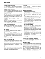
... enables parallel operation if a loop connection has been established between the VTR and another VTR. 8-channel high-sound-quality digital audio The 8-channel PCM audio feature allows for 8 channels are featured as the LTC on a TV monitor. This one BNC connector enables HD component video signals and 8-channels digital audio signals to the internal time code, an external time code can also be input and recorded as a standard accessory. • SDTI input/output connector Use of 50...
... enables parallel operation if a loop connection has been established between the VTR and another VTR. 8-channel high-sound-quality digital audio The 8-channel PCM audio feature allows for 8 channels are featured as the LTC on a TV monitor. This one BNC connector enables HD component video signals and 8-channels digital audio signals to the internal time code, an external time code can also be input and recorded as a standard accessory. • SDTI input/output connector Use of 50...
AJHD1700 User Guide
Page 9
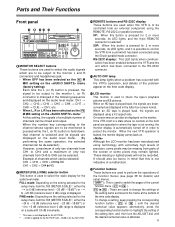
... external component using the 50-pin parallel mode connector. Although the LCD monitor has been manufactured using a 4:3 aspect ratio. POWER OFF ON HEADPHONES CH1 2 CH CONDITION 3 4 5 6 7 8 CUE MONITOR FULL/FINE 9P L R REMOTE 50P RS-232C XL/L/M-cassette Do not insert S-cassette without adapter HOME RF1 RF2 ASSEM VIDEO UNITY TC AUDIO UNITY DIAG CUE INSERT MENU ADJUST PUSH-INTER STAND BY PLAYER RECORDER INPUT...
... external component using the 50-pin parallel mode connector. Although the LCD monitor has been manufactured using a 4:3 aspect ratio. POWER OFF ON HEADPHONES CH1 2 CH CONDITION 3 4 5 6 7 8 CUE MONITOR FULL/FINE 9P L R REMOTE 50P RS-232C XL/L/M-cassette Do not insert S-cassette without adapter HOME RF1 RF2 ASSEM VIDEO UNITY TC AUDIO UNITY DIAG CUE INSERT MENU ADJUST PUSH-INTER STAND BY PLAYER RECORDER INPUT...

AJHD1700 User Guide
Page 10
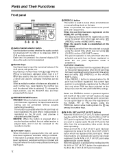
... (AUDIO UNITY).) @ Direct menu buttons These buttons are selected. REVIEW ROLL A OUT AUTO EDIT TRIM SET IN OUT EDIT REW SERVO PLAY REC INHIBIT REC STOP FF EJECT SHTL JOG VAR REV FWD FULL ?B > Time code display The data, VTR status information, tape format information or warning information which operations (adjustments and saving data in the function keys. AUDIO: The basic input and output settings for the video signals are selected on this screen...
... (AUDIO UNITY).) @ Direct menu buttons These buttons are selected. REVIEW ROLL A OUT AUTO EDIT TRIM SET IN OUT EDIT REW SERVO PLAY REC INHIBIT REC STOP FF EJECT SHTL JOG VAR REV FWD FULL ?B > Time code display The data, VTR status information, tape format information or warning information which operations (adjustments and saving data in the function keys. AUDIO: The basic input and output settings for the video signals are selected on this screen...

AJHD1700 User Guide
Page 11
... the clockwise direction, it lights when the dial is turned. Parts and Their Functions Front panel HD EF POWER OFF ON HEADPHONES CH1 2 CH CONDITION 3 4 5 6 7 8 CUE MONITOR FULL/FINE 9P L R REMOTE 50P RS-232C XL/L/M-cassette Do not insert S-cassette without adapter HOME RF1 RF2 ASSEM VIDEO UNITY TC AUDIO UNITY DIAG CUE INSERT MENU ADJUST PUSH-INTER STAND BY PLAYER RECORDER INPUT CHECK AUDIO CH SELECT...
... the clockwise direction, it lights when the dial is turned. Parts and Their Functions Front panel HD EF POWER OFF ON HEADPHONES CH1 2 CH CONDITION 3 4 5 6 7 8 CUE MONITOR FULL/FINE 9P L R REMOTE 50P RS-232C XL/L/M-cassette Do not insert S-cassette without adapter HOME RF1 RF2 ASSEM VIDEO UNITY TC AUDIO UNITY DIAG CUE INSERT MENU ADJUST PUSH-INTER STAND BY PLAYER RECORDER INPUT CHECK AUDIO CH SELECT...
AJHD1700 User Guide
Page 12
...) point is played back, and it was set using the preroll time which are used for channels CH5 to CH8 are allocated to F which was set using this button is registered as the setup menu item No.305 (AUTO ENTRY) setting). K Number keys Use these buttons are used to input the numerical values of the IN (A IN) or OUT (A OUT) button which has registered that differ from the registered...
...) point is played back, and it was set using the preroll time which are used for channels CH5 to CH8 are allocated to F which was set using this button is registered as the setup menu item No.305 (AUTO ENTRY) setting). K Number keys Use these buttons are used to input the numerical values of the IN (A IN) or OUT (A OUT) button which has registered that differ from the registered...

AJHD1700 User Guide
Page 14
... set to the standby ON mode. Select LATCH as in the E-E mode. 14 Parts and Their Functions Front panel YZ[ POWER OFF ON HEADPHONES CH1 2 CH CONDITION 3 4 5 6 7 8 CUE MONITOR FULL/FINE 9P L R REMOTE 50P RS-232C XL/L/M-cassette Do not insert S-cassette without adapter HOME RF1 RF2 ASSEM VIDEO UNITY TC AUDIO UNITY DIAG CUE INSERT MENU ADJUST PUSH-INTER STAND BY PLAYER RECORDER INPUT...
... set to the standby ON mode. Select LATCH as in the E-E mode. 14 Parts and Their Functions Front panel YZ[ POWER OFF ON HEADPHONES CH1 2 CH CONDITION 3 4 5 6 7 8 CUE MONITOR FULL/FINE 9P L R REMOTE 50P RS-232C XL/L/M-cassette Do not insert S-cassette without adapter HOME RF1 RF2 ASSEM VIDEO UNITY TC AUDIO UNITY DIAG CUE INSERT MENU ADJUST PUSH-INTER STAND BY PLAYER RECORDER INPUT...
AJHD1700 User Guide
Page 16
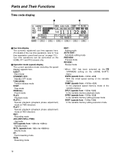
... mode FF: Fast forwarding mode REW: Rewinding mode EDIT: Editing mode AUTO EDIT: Automatic editing mode PREVIEW: Preview mode REVIEW: Review mode • When "ON" has been selected as the [FF6] (VARMEM) setting on the HOME, PF1 and PF2 screens only. 2 Operation mode (speed) display The current operation mode (including the speed display) appears here. Parts and Their Functions Time code display 1 2 SHIFT F1 F2 F3 F4 F5 F6 1 Cue time display The currently registered cue time...
... mode FF: Fast forwarding mode REW: Rewinding mode EDIT: Editing mode AUTO EDIT: Automatic editing mode PREVIEW: Preview mode REVIEW: Review mode • When "ON" has been selected as the [FF6] (VARMEM) setting on the HOME, PF1 and PF2 screens only. 2 Operation mode (speed) display The current operation mode (including the speed display) appears here. Parts and Their Functions Time code display 1 2 SHIFT F1 F2 F3 F4 F5 F6 1 Cue time display The currently registered cue time...

AJHD1700 User Guide
Page 23
... push it in mind that inserting a cassette tape without adapter HOME RF1 RF2 ASSEM VIDEO UNITY TC AUDIO UNITY DIAG CUE INSERT MENU ADJUST PUSH-INTER STAND BY PLAYER RECORDER INPUT CHECK AUDIO CH SELECT CH 1 CH 5 CH 2 CH 6 CH 3 CH 7 CH 4 CH 8 FULL REC P8 PUSH LOCK REC P8 REC P8 REC P8 SHIFT F1 F2 ABC DEF GHI 789 JKL MNO...
... push it in mind that inserting a cassette tape without adapter HOME RF1 RF2 ASSEM VIDEO UNITY TC AUDIO UNITY DIAG CUE INSERT MENU ADJUST PUSH-INTER STAND BY PLAYER RECORDER INPUT CHECK AUDIO CH SELECT CH 1 CH 5 CH 2 CH 6 CH 3 CH 7 CH 4 CH 8 FULL REC P8 PUSH LOCK REC P8 REC P8 REC P8 SHIFT F1 F2 ABC DEF GHI 789 JKL MNO...

AJHD1700 User Guide
Page 25
... . The playback pictures will be recorded. 2 Select the input signals using F1 on the menu. Selecting the video and audio input signals 1 Connect the signals to be set for the CH1 to CH4 signals. • When SDTI has been selected as the CH5 to CH8 input signals on the AUDIO menu, their recording levels are also automatically set to SDTI. The REC and PLAY lamps light, and recording starts...
... . The playback pictures will be recorded. 2 Select the input signals using F1 on the menu. Selecting the video and audio input signals 1 Connect the signals to be set for the CH1 to CH4 signals. • When SDTI has been selected as the CH5 to CH8 input signals on the AUDIO menu, their recording levels are also automatically set to SDTI. The REC and PLAY lamps light, and recording starts...

AJHD1700 User Guide
Page 41
... SETTINGS The most basic settings for recording, playback and TC operations are displayed for the F1 function button, making it may not be possible to check the currently selected system frequency mode. The 25 (HD) Hz mode is invalid. Status display 1 Warning mark Name of settings These settings indicate the DVCPRO HD-LP recording and playback mode. Variable memory mode indicator Status display 1 VTR PB FMT REC FMT*1 TM INFO*2 Playback format This displays the format used for playback...
... SETTINGS The most basic settings for recording, playback and TC operations are displayed for the F1 function button, making it may not be possible to check the currently selected system frequency mode. The 25 (HD) Hz mode is invalid. Status display 1 Warning mark Name of settings These settings indicate the DVCPRO HD-LP recording and playback mode. Variable memory mode indicator Status display 1 VTR PB FMT REC FMT*1 TM INFO*2 Playback format This displays the format used for playback...

AJHD1700 User Guide
Page 46
... (VIDEO IN SEL) and No.713 (CH1 IN SEL) to the setup menu. OFF: The variable memory mode is displayed. CTL: The control signal (time data) is displayed. For resetting the time counter display. UB: The user's bit value is displayed. Refer to the setup menu. ___ Refer to No.724 (D IN SEL 78) settings are output. Function menus Function button/item F1 OUTPUT Switching method Setting Toggle TAPE EE Corresponding setup menu...
... (VIDEO IN SEL) and No.713 (CH1 IN SEL) to the setup menu. OFF: The variable memory mode is displayed. CTL: The control signal (time data) is displayed. For resetting the time counter display. UB: The user's bit value is displayed. Refer to the setup menu. ___ Refer to No.724 (D IN SEL 78) settings are output. Function menus Function button/item F1 OUTPUT Switching method Setting Toggle TAPE EE Corresponding setup menu...
AJHD1700 User Guide
Page 60
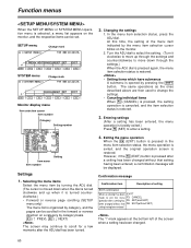
... display menu Item selection cursor Item number Category Setting number 2. In the menu item selection status, press the ADJ dial. Turn the ADJ dial to select the setting. (Turn it is turned counterclockwise.) • Forward or reverse page scrolling (SETUP menu only) The menu list is organized by category, and the pages can be set. The same operations as the ones described above are then used to change...
... display menu Item selection cursor Item number Category Setting number 2. In the menu item selection status, press the ADJ dial. Turn the ADJ dial to select the setting. (Turn it is turned counterclockwise.) • Forward or reverse page scrolling (SETUP menu only) The menu list is organized by category, and the pages can be set. The same operations as the ones described above are then used to change...

AJHD1700 User Guide
Page 81
... set in the REMOTE mode. 0000 DIS: No buttons can be operated. 0001 ST&EJ: Only the STOP and EJECT buttons can be operated. 0002 ENA: All the buttons except for the RECORDER and PLAYER buttons can be superimposed onto the HD SDI MONITOR, SD SDI MONITOR and VIDEO OUT3 connectors. 0000 TIME: Only the time is displayed. 0001 T&STA: The time and operation mode are displayed. 0002 T&S&M: The time, operation mode and mode...
... set in the REMOTE mode. 0000 DIS: No buttons can be operated. 0001 ST&EJ: Only the STOP and EJECT buttons can be operated. 0002 ENA: All the buttons except for the RECORDER and PLAYER buttons can be superimposed onto the HD SDI MONITOR, SD SDI MONITOR and VIDEO OUT3 connectors. 0000 TIME: Only the time is displayed. 0001 T&STA: The time and operation mode are displayed. 0002 T&S&M: The time, operation mode and mode...

AJHD1700 User Guide
Page 84
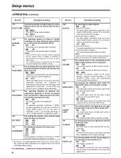
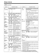
...*1 AUTO EE SEL For selecting the VTR mode which is to be set using setup menu item No.307 (AFTER CUE-UP), is established when the VTR is selected during video input signal selection. 108 PLAY DELAY For setting the play startup time in 1-frame increments. 0000 0 : : 0015 15 109*1 CAP. The internal operation forcibly sets "NORMAL" when an editing mode is selected or when SDTI is...
...*1 AUTO EE SEL For selecting the VTR mode which is to be set using setup menu item No.307 (AFTER CUE-UP), is established when the VTR is selected during video input signal selection. 108 PLAY DELAY For setting the play startup time in 1-frame increments. 0000 0 : : 0015 15 109*1 CAP. The internal operation forcibly sets "NORMAL" when an editing mode is selected or when SDTI is...

AJHD1700 User Guide
Page 85
..., it is preferable to avoid using normal recording in the output format of the HD serial output signals when operation has transferred to the EJECT mode. Use this setting when it automatically stops when the counter value is at all applications except for audio editing. and then off for approx. 0.5 sec. The underlining (__) denotes the factory setting mode. Use this setting when it is executed. 0003...
..., it is preferable to avoid using normal recording in the output format of the HD serial output signals when operation has transferred to the EJECT mode. Use this setting when it automatically stops when the counter value is at all applications except for audio editing. and then off for approx. 0.5 sec. The underlining (__) denotes the factory setting mode. Use this setting when it is executed. 0003...
AJHD1700 User Guide
Page 86
... operation if all the audio input and output levels are output: 0001 TAPE: The signals played back from the right-most digit. 145 FRONT LCD For selecting whether the LCD monitor display on the front panel is not displayed when the 23/24 Hz or 25 Hz (HD or SD) mode has been selected as the system menu item No.25 (SYSTEM FREQ) setting...
... operation if all the audio input and output levels are output: 0001 TAPE: The signals played back from the right-most digit. 145 FRONT LCD For selecting whether the LCD monitor display on the front panel is not displayed when the 23/24 Hz or 25 Hz (HD or SD) mode has been selected as the system menu item No.25 (SYSTEM FREQ) setting...
AJHD1700 User Guide
Page 92
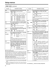
... playback mode, the time code recorded in the SBC area is output. 0001 VAUX: In the playback mode, the time code recorded in the VAUX area is automatically recorded in response to the external LTC input when a setting other than the EE mode. It can be read even during rewinding or fast forwarding. VAUX (video auxiliary data) area: This area is set to a mode other than "INT" has been selected for setup menu...
... playback mode, the time code recorded in the SBC area is output. 0001 VAUX: In the playback mode, the time code recorded in the VAUX area is automatically recorded in response to the external LTC input when a setting other than the EE mode. It can be read even during rewinding or fast forwarding. VAUX (video auxiliary data) area: This area is set to a mode other than "INT" has been selected for setup menu...
AJHD1700 User Guide
Page 97
...data superimposed on the compressed input signals is recorded on the tape in accordance with a 7.5% setup added. 0002 ADD20L: The signal is not displayed when the 23/24 Hz or 25 Hz (HD) mode has been selected as is. 0001 ON: The cross color can be set for edge subcarrier reduction (ESR) in the playback... ESR is automatically set and the SHIFT button is pressed, the display transfers to the submenu screen where the ON or OFF can be reduced. 687*4 SDI INDEX 0 *DW For selecting whether to superimpose the VIDEO INDEX signal on the SD SDI output signal. 0000 OFF: The VIDEO INDEX signal is ...
...data superimposed on the compressed input signals is recorded on the tape in accordance with a 7.5% setup added. 0002 ADD20L: The signal is not displayed when the 23/24 Hz or 25 Hz (HD) mode has been selected as is. 0001 ON: The cross color can be set for edge subcarrier reduction (ESR) in the playback... ESR is automatically set and the SHIFT button is pressed, the display transfers to the submenu screen where the ON or OFF can be reduced. 687*4 SDI INDEX 0 *DW For selecting whether to superimpose the VIDEO INDEX signal on the SD SDI output signal. 0000 OFF: The VIDEO INDEX signal is ...

AJHD1700 User Guide
Page 111
... (8-digit) data frame among the number keys is pressed, the TC display switches to TCG (UBG), and the TCG value characters (all other values to be recorded. Setting the internal time code 1 Set the VTR to the stop mode to the slow motion playback up to be cleared by pressing 0 while holding down F . Time code and user's bit Time code The time code is used when the time code signal generated by the time code...
... (8-digit) data frame among the number keys is pressed, the TC display switches to TCG (UBG), and the TCG value characters (all other values to be recorded. Setting the internal time code 1 Set the VTR to the stop mode to the slow motion playback up to be cleared by pressing 0 while holding down F . Time code and user's bit Time code The time code is used when the time code signal generated by the time code...


