
Owner Manual
Page 2
..., such as power-supply cord or plug is damaged, liquid has been spilled or objects have fallen into your safety. The apparatus shall not be set 10 cm (4") away from tip-over. The rear edge of this apparatus during lightning storms or when unused for warm air to persons. WARNING: TO...
..., such as power-supply cord or plug is damaged, liquid has been spilled or objects have fallen into your safety. The apparatus shall not be set 10 cm (4") away from tip-over. The rear edge of this apparatus during lightning storms or when unused for warm air to persons. WARNING: TO...
Owner Manual
Page 3
...the correct voltage for an extended period, remove the power cord from country to disconnect this unit or its power cord while your Onkyo dealer. 3. NOTE: This equipment has been tested and found to comply with Wet Hands-Never handle this unit from that interference will...for a Class B digital device, pursuant to Part 15 of the following measures: • Reorient or relocate the receiving antenna. • Increase the separation between 220 and 240 volts, set to the correct voltage for a long time, because they may cause harmful interference to select Standby mode does not fully...
...the correct voltage for an extended period, remove the power cord from country to disconnect this unit or its power cord while your Onkyo dealer. 3. NOTE: This equipment has been tested and found to comply with Wet Hands-Never handle this unit from that interference will...for a Class B digital device, pursuant to Part 15 of the following measures: • Reorient or relocate the receiving antenna. • Increase the separation between 220 and 240 volts, set to the correct voltage for a long time, because they may cause harmful interference to select Standby mode does not fully...
Owner Manual
Page 6
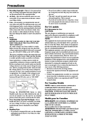
... B You can be used in your source component with the AV receiver: speaker set A and speaker set B is reduced to 7.1-channel playback. *While speaker set B is on, speaker set A is on, the surround back speakers output no sound. 6 * Digital input sources are output by speaker set B. STANDBY/ON STANDBY PHONES A SPEAKETRUNSING BPRESET MASTER VOLUME MULTI CH A SPEAKERS...
... B You can be used in your source component with the AV receiver: speaker set A and speaker set B is reduced to 7.1-channel playback. *While speaker set B is on, speaker set A is on, the surround back speakers output no sound. 6 * Digital input sources are output by speaker set B. STANDBY/ON STANDBY PHONES A SPEAKETRUNSING BPRESET MASTER VOLUME MULTI CH A SPEAKERS...

Owner Manual
Page 7
...MiniDisc, or DAT Recorder 32 Onkyo Components 33 Connecting the Power Cord 33 Turning On & First Time Setup Turning On the AV Receiver 34 First Time Setup 35 Automatic Speaker Setup (Audyssey 2EQ 35 Video Input Setup (TX-SR505 North American Model/ TX-SR505E/TX-SR575 Only 38 Digital Audio Input Setup... 42 Presetting AM/FM Stations 43 Using RDS (European Models Only 44 Common Functions 46 Setting the Display Brightness 46 Adjusting the Bass and Treble 46 Muting the AV Receiver 46 Using the Sleep Timer 47 Using Headphones 47 Adjusting Speaker Levels 47 Enjoying the Listening...
...MiniDisc, or DAT Recorder 32 Onkyo Components 33 Connecting the Power Cord 33 Turning On & First Time Setup Turning On the AV Receiver 34 First Time Setup 35 Automatic Speaker Setup (Audyssey 2EQ 35 Video Input Setup (TX-SR505 North American Model/ TX-SR505E/TX-SR575 Only 38 Digital Audio Input Setup... 42 Presetting AM/FM Stations 43 Using RDS (European Models Only 44 Common Functions 46 Setting the Display Brightness 46 Adjusting the Bass and Treble 46 Muting the AV Receiver 46 Using the Sleep Timer 47 Using Headphones 47 Adjusting Speaker Levels 47 Enjoying the Listening...

Owner Manual
Page 8
A STANDBY/ON button (34) Sets the AV receiver to MIN, 1 through 79, or MAX. B STANDBY indicator (34) Lights up when the AV receiver is on or off. 8 The [MULTI CH] button selects the multichannel DVD input. With the setup menus, they work as arrow buttons and are ... is selected, the TUNING [ ] [ ] buttons are used for private listening. H PHONES jack (47) This 1/4-inch phone jack is for connecting a standard pair of the AV receiver to On or Standby. G MASTER VOLUME control (40) Sets the volume of stereo headphones for radio tuning, and the PRESET [ ] [ ] buttons are used to Know the...
A STANDBY/ON button (34) Sets the AV receiver to MIN, 1 through 79, or MAX. B STANDBY indicator (34) Lights up when the AV receiver is on or off. 8 The [MULTI CH] button selects the multichannel DVD input. With the setup menus, they work as arrow buttons and are ... is selected, the TUNING [ ] [ ] buttons are used for private listening. H PHONES jack (47) This 1/4-inch phone jack is for connecting a standard pair of the AV receiver to On or Standby. G MASTER VOLUME control (40) Sets the volume of stereo headphones for radio tuning, and the PRESET [ ] [ ] buttons are used to Know the...

Owner Manual
Page 9
...Show the audio signal format of digital input signals. Getting to Know the AV Receiver-Continued J TONE, [-], and [+] buttons (46) Used to connect a camcorder, games console, and so on. Indicator B lights up when speaker set . 7 Message area Displays various information about the currently selected input source....source. 8 Audyssey indicator (35) Lights up when the Sleep function has been set B is on page 44. See "Using RDS (European Models Only)" on . 2 MUTING indicator (46) Flashes while the AV receiver is selected. V PURE AUDIO button and indicator (48) The North American model ...
...Show the audio signal format of digital input signals. Getting to Know the AV Receiver-Continued J TONE, [-], and [+] buttons (46) Used to connect a camcorder, games console, and so on. Indicator B lights up when speaker set . 7 Message area Displays various information about the currently selected input source....source. 8 Audyssey indicator (35) Lights up when the Sleep function has been set B is on page 44. See "Using RDS (European Models Only)" on . 2 MUTING indicator (46) Flashes while the AV receiver is selected. V PURE AUDIO button and indicator (48) The North American model ...

Owner Manual
Page 11
...see the separate XM instructions). F MONITOR OUT The S-Video or composite video output should be used to a video input on another -capable Onkyo com- O SUBWOOFER PRE OUT A powered subwoofer can be connected to connect a VCR or DVR (digital video recorder). I FRONT SPEAKERS A, ...and OUT (TX-SR505 North American model/TX-SR505E/ TX-SR575 only) These jacks are for hookup information. 11 Audio and video signals received by the HDMI IN jacks pass through to connect a cable/satellite receiver, set A. To use , you must make an analog audio connection (RCA) between the AV receiver and the...
...see the separate XM instructions). F MONITOR OUT The S-Video or composite video output should be used to a video input on another -capable Onkyo com- O SUBWOOFER PRE OUT A powered subwoofer can be connected to connect a VCR or DVR (digital video recorder). I FRONT SPEAKERS A, ...and OUT (TX-SR505 North American model/TX-SR505E/ TX-SR575 only) These jacks are for hookup information. 11 Audio and video signals received by the HDMI IN jacks pass through to connect a cable/satellite receiver, set A. To use , you must make an analog audio connection (RCA) between the AV receiver and the...

Owner Manual
Page 13
...RECEIVER 7 TAPE 4 Playback buttons On twin cassette decks, only deck B can be controlled. Reverse Play [ ] button Starts reverse playback. SURROUND button Selects the Dolby and DTS listening modes and the Neural Surround listening mode (TX-SR575 North American model only). [ ]/[ ] buttons Used to turn speaker sets... (48) Used to select the remote controller modes. A STANDBY/ON button (34) Sets the AV receiver to select and adjust settings. M VOL [ ]/[ ] button (40) Adjusts the volume of the AV receiver regardless of each speaker. Rewind and FF [ ]/[ ] buttons The Rewind [ ]...
...RECEIVER 7 TAPE 4 Playback buttons On twin cassette decks, only deck B can be controlled. Reverse Play [ ] button Starts reverse playback. SURROUND button Selects the Dolby and DTS listening modes and the Neural Surround listening mode (TX-SR575 North American model only). [ ]/[ ] buttons Used to turn speaker sets... (48) Used to select the remote controller modes. A STANDBY/ON button (34) Sets the AV receiver to select and adjust settings. M VOL [ ]/[ ] button (40) Adjusts the volume of the AV receiver regardless of each speaker. Rewind and FF [ ]/[ ] buttons The Rewind [ ]...
Owner Manual
Page 14
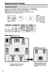
.... LEVEL+ PLAY MODE DISPLAY L NIGHT VCR DVD CINE FLTR HDD RC-681M DVD K L M N O P Q A STANDBY/ON button Sets the DVD player to right: Pause, Play, Stop, Fast Reverse, Fast Forward, Previous, and Next. To select your DVD player as the ...RECEIVER DVD TAPE/AMP INPUT SELECTOR M D/CDR 1 2 3 VCR/DVR CBL/SAT C D DOCK 4 5 6 TV AUX MULTI CH DVD 7 8 9 VCR TAPE TUNER 10 11 +10 0 C D 12 CABLE CLR SAT D TUN --/--- O REPEAT button Used with a built-in hard disk drive. Remote Controller-Continued DVD Mode By default, the remote controller is set to control an Onkyo...
.... LEVEL+ PLAY MODE DISPLAY L NIGHT VCR DVD CINE FLTR HDD RC-681M DVD K L M N O P Q A STANDBY/ON button Sets the DVD player to right: Pause, Play, Stop, Fast Reverse, Fast Forward, Previous, and Next. To select your DVD player as the ...RECEIVER DVD TAPE/AMP INPUT SELECTOR M D/CDR 1 2 3 VCR/DVR CBL/SAT C D DOCK 4 5 6 TV AUX MULTI CH DVD 7 8 9 VCR TAPE TUNER 10 11 +10 0 C D 12 CABLE CLR SAT D TUN --/--- O REPEAT button Used with a built-in hard disk drive. Remote Controller-Continued DVD Mode By default, the remote controller is set to control an Onkyo...

Owner Manual
Page 15
... RANDOM REPEAT TEST TONE CH SEL LEVEL- LEVEL+ PLAY MODE DISPLAY L NIGHT VCR DVD CINE FLTR HDD RC-681M K L M A STANDBY/ON button Sets the component to control an Onkyo CD player. C DISC/ALBUM +/- D TOP MENU button Works as a Resume button when used with a DS-A2 RI Dock. On an HDD-compatible... component connected to an RI Dock. Remote Controller-Continued CD/MD/CDR/DOCK Mode By default, the remote controller is set to On or Standby. To select the input source, press: RECEIVER 9 CD player C D 7 MD or CD recorder TAPE 7 TAPE or 2 RI Dock CBL/SAT * If you're using an MD, ...
... RANDOM REPEAT TEST TONE CH SEL LEVEL- LEVEL+ PLAY MODE DISPLAY L NIGHT VCR DVD CINE FLTR HDD RC-681M K L M A STANDBY/ON button Sets the component to control an Onkyo CD player. C DISC/ALBUM +/- D TOP MENU button Works as a Resume button when used with a DS-A2 RI Dock. On an HDD-compatible... component connected to an RI Dock. Remote Controller-Continued CD/MD/CDR/DOCK Mode By default, the remote controller is set to On or Standby. To select the input source, press: RECEIVER 9 CD player C D 7 MD or CD recorder TAPE 7 TAPE or 2 RI Dock CBL/SAT * If you're using an MD, ...

Owner Manual
Page 17
... spaced from your subwoofer at various positions within the room, and choose the one that you 're using the AV receiver, you should use , a powered subwoofer is to create a triangle, with a real sense of speakers: 2...left and right sound and improve sound local- You can enjoy Dolby Pro Logic IIx and Onkyo's own DSP surround listening modes. ization behind the listener about 2-3 feet (60-100 cm... your subwoofer will depend on its position, the shape of the bass * While speaker set B is on the number of the LFE (Low-Frequency Effects) channel. The following ...
... spaced from your subwoofer at various positions within the room, and choose the one that you 're using the AV receiver, you should use , a powered subwoofer is to create a triangle, with a real sense of speakers: 2...left and right sound and improve sound local- You can enjoy Dolby Pro Logic IIx and Onkyo's own DSP surround listening modes. ization behind the listener about 2-3 feet (60-100 cm... your subwoofer will depend on its position, the shape of the bass * While speaker set B is on the number of the LFE (Low-Frequency Effects) channel. The following ...
Owner Manual
Page 18
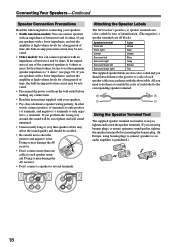
....) 18 All you get them to match the color of each speaker cable in accordance with the above table. Attaching the Speaker Labels The AV receiver's positive (+) speaker terminals are color-coded for a long period of phase and will sound unnatural. • Unnecessarily long or very thin ...speaker cables may affect the sound quality and should be sure to set the minimum speaker impedance to the corresponding speaker terminal. If you are also color-coded and you use speakers with a lower impedance, ...
....) 18 All you get them to match the color of each speaker cable in accordance with the above table. Attaching the Speaker Labels The AV receiver's positive (+) speaker terminals are color-coded for a long period of phase and will sound unnatural. • Unnecessarily long or very thin ...speaker cables may affect the sound quality and should be sure to set the minimum speaker impedance to the corresponding speaker terminal. If you are also color-coded and you use speakers with a lower impedance, ...
Owner Manual
Page 19
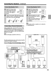
... the insulation. 3/8" (10 mm) Note: While speaker set B is on your subwoofer is reduced to the left speaker 19 Screw the terminal tight. Connecting a Powered Subwoofer Using a suitable cable, connect the AV receiver's SUBWOOFER PRE OUT to each pair of terminals. Front ...right speaker Speaker Set A Front left speaker The following illustration shows which speaker should be connected to the input...
... the insulation. 3/8" (10 mm) Note: While speaker set B is on your subwoofer is reduced to the left speaker 19 Screw the terminal tight. Connecting a Powered Subwoofer Using a suitable cable, connect the AV receiver's SUBWOOFER PRE OUT to each pair of terminals. Front ...right speaker Speaker Set A Front left speaker The following illustration shows which speaker should be connected to the input...
Owner Manual
Page 24
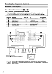
...no audio outputs, connect an audio output from your TV and listen via speaker set B. • To enjoy Dolby Digital and DTS, use connection b or c . (For recording, use its tuner to listen to TV programs through the AV receiver (see page 39) TV, projector, etc. IAL 1 Y (DVD) ...Components-Continued Connecting a TV or Projector Step 1: Choose a video connection from your VCR or cable or satellite receiver to the AV receiver and use a and b , or a and c .) Connection A B C a b c AV receiver COMPONENT VIDEO OUT MONITOR OUT S MONITOR OUT V CBL/SAT IN L/R DIGITAL IN COAXIAL 2 DIGITAL IN ...
...no audio outputs, connect an audio output from your TV and listen via speaker set B. • To enjoy Dolby Digital and DTS, use connection b or c . (For recording, use its tuner to listen to TV programs through the AV receiver (see page 39) TV, projector, etc. IAL 1 Y (DVD) ...Components-Continued Connecting a TV or Projector Step 1: Choose a video connection from your VCR or cable or satellite receiver to the AV receiver and use a and b , or a and c .) Connection A B C a b c AV receiver COMPONENT VIDEO OUT MONITOR OUT S MONITOR OUT V CBL/SAT IN L/R DIGITAL IN COAXIAL 2 DIGITAL IN ...

Owner Manual
Page 25
... OPTICAL OUT Y PB PR COMPONENT VIDEO OUT L R AUDIO OUT S VIDEO OUT VIDEO OUT Connect one or the other Connection c must connect the AV receiver to your TV via speaker set B. • To enjoy Dolby Digital and DTS, use connection b or c . (For recording, use a and b , or a and c...DVD-Audio/SACD-capable player with a multichannel analog audio output, see page 26. 25 Connection A B C a b c AV receiver COMPONENT VIDEO DVD IN (TX-SR505/TX-SR505E/TX-SR8550) or COMPONENT VIDEO IN 1 (TX-SR575) DVD IN S DVD IN V DVD IN FRONT DIGITAL IN COAXIAL 1 DIGITAL IN OPTICAL 1 Signal flow DVD ...
... OPTICAL OUT Y PB PR COMPONENT VIDEO OUT L R AUDIO OUT S VIDEO OUT VIDEO OUT Connect one or the other Connection c must connect the AV receiver to your TV via speaker set B. • To enjoy Dolby Digital and DTS, use connection b or c . (For recording, use a and b , or a and c...DVD-Audio/SACD-capable player with a multichannel analog audio output, see page 26. 25 Connection A B C a b c AV receiver COMPONENT VIDEO DVD IN (TX-SR505/TX-SR505E/TX-SR8550) or COMPONENT VIDEO IN 1 (TX-SR575) DVD IN S DVD IN V DVD IN FRONT DIGITAL IN COAXIAL 1 DIGITAL IN OPTICAL 1 Signal flow DVD ...

Owner Manual
Page 28
... a , you can listen to your favorite TV programs via the AV receiver, useful if your TV via speaker set B. • To enjoy Dolby Digital and DTS, use a and b , or a and c .) Connection A B C a b c AV receiver COMPONENT VIDEO VCR/DVR IN (TX-SR505/TX-SR505E/TX-SR8550) or COMPONENT VIDEO IN 2 (TX-SR575) VCR/DVR IN S VCR/DVR IN V VCR/DVR IN L/R DIGITAL...
... a , you can listen to your favorite TV programs via the AV receiver, useful if your TV via speaker set B. • To enjoy Dolby Digital and DTS, use a and b , or a and c .) Connection A B C a b c AV receiver COMPONENT VIDEO VCR/DVR IN (TX-SR505/TX-SR505E/TX-SR8550) or COMPONENT VIDEO IN 2 (TX-SR575) VCR/DVR IN S VCR/DVR IN V VCR/DVR IN L/R DIGITAL...

Owner Manual
Page 30
...of connection. Connecting Your Components-Continued Connecting a Satellite, Cable, Set-top box, or Other Video Source Hint! With this hookup, you can use a and b , or a and c .) Connection A B C a b c AV receiver COMPONENT VIDEO CBL/SAT IN (TX-SR505/TX-SR505E/TXSR8550) or COMPONENT VIDEO IN 3 (TX-SR575) CBL/SAT IN S CBL/SAT IN V CBL/SAT ... Y PB PR COMPONENT VIDEO OUT L R AUDIO OUT S VIDEO OUT VIDEO OUT Connect one or the other Connection c must connect the AV receiver to your favorite TV programs via the AV receiver, useful if your TV via speaker set -top box, etc. 30
...of connection. Connecting Your Components-Continued Connecting a Satellite, Cable, Set-top box, or Other Video Source Hint! With this hookup, you can use a and b , or a and c .) Connection A B C a b c AV receiver COMPONENT VIDEO CBL/SAT IN (TX-SR505/TX-SR505E/TXSR8550) or COMPONENT VIDEO IN 3 (TX-SR575) CBL/SAT IN S CBL/SAT IN V CBL/SAT ... Y PB PR COMPONENT VIDEO OUT L R AUDIO OUT S VIDEO OUT VIDEO OUT Connect one or the other Connection c must connect the AV receiver to your favorite TV programs via the AV receiver, useful if your TV via speaker set -top box, etc. 30
Owner Manual
Page 31
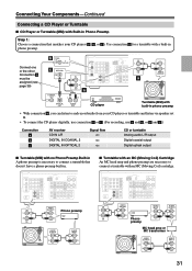
... preamp are necessary to and record audio from your CD player or turntable and listen via speaker set B. • To connect the CD player digitally, use connection b or c . (For recording, use a and b , or a and c .) Connection a b c AV receiver CD IN L/R DIGITAL IN COAXIAL 2 DIGITAL IN OPTICAL 2 Signal flow ⇐ ⇐ ⇐ CD or...
... preamp are necessary to and record audio from your CD player or turntable and listen via speaker set B. • To connect the CD player digitally, use connection b or c . (For recording, use a and b , or a and c .) Connection a b c AV receiver CD IN L/R DIGITAL IN COAXIAL 2 DIGITAL IN OPTICAL 2 Signal flow ⇐ ⇐ ⇐ CD or...

Owner Manual
Page 32
...CBL/SAT IN S jack. ■ RI Dock without video Connect your RI Dock's analog audio output jacks to the AV receiver's TAPE IN L/R jacks (1). R R IN OUT REC PLAY Connection a b c AV receiver TAPE IN L/R TAPE OUT L/R DIGITAL IN COAXIAL 2 DIGITAL IN OPTICAL 1 Signal flow Cassette/CDR/MD/DAT recorder... Your Components-Continued Connecting an RI Dock ■ RI Dock with an cable (see page 33). • Set the Remote Interactive Dock's RI MODE switch to HDD or HDD/DOCK. • Set the AV receiver's Input Display to DOCK (see page 39) b COAXIAL 2 (CBL/SAT) c OPTICAL 1 (VCR/DVR...
...CBL/SAT IN S jack. ■ RI Dock without video Connect your RI Dock's analog audio output jacks to the AV receiver's TAPE IN L/R jacks (1). R R IN OUT REC PLAY Connection a b c AV receiver TAPE IN L/R TAPE OUT L/R DIGITAL IN COAXIAL 2 DIGITAL IN OPTICAL 1 Signal flow Cassette/CDR/MD/DAT recorder... Your Components-Continued Connecting an RI Dock ■ RI Dock with an cable (see page 33). • Set the Remote Interactive Dock's RI MODE switch to HDD or HDD/DOCK. • Set the AV receiver's Input Display to DOCK (see page 39) b COAXIAL 2 (CBL/SAT) c OPTICAL 1 (VCR/DVR...

Owner Manual
Page 33
... first (page 63). Notes: • Before connecting the power cord, connect all components connected via , the AV receiver automatically selects that each Onkyo component is set to control your speakers and AV components. • Turning on the AV receiver may not support all channels (see page 41), as the Direct Change function only selects the FRONT...
... first (page 63). Notes: • Before connecting the power cord, connect all components connected via , the AV receiver automatically selects that each Onkyo component is set to control your speakers and AV components. • Turning on the AV receiver may not support all channels (see page 41), as the Direct Change function only selects the FRONT...


