
Owner Manual
Page 2
... the user to the presence of uninsulated "dangerous voltage" within an equilateral triangle, is damaged, B. Important Safety Instructions 1. A grounding type plug has two blades and a third grounding prong. Protect the power cord from being walked on the apparatus. Only use attachments/accessories ...gap for service. 16. Install in performance this apparatus during lightning storms or when unused for long periods of the polarized or grounding-type plug. tors, heat registers, stoves, or other controls may be placed on or pinched particularly at the rear. facturer, or ...
... the user to the presence of uninsulated "dangerous voltage" within an equilateral triangle, is damaged, B. Important Safety Instructions 1. A grounding type plug has two blades and a third grounding prong. Protect the power cord from being walked on the apparatus. Only use attachments/accessories ...gap for service. 16. Install in performance this apparatus during lightning storms or when unused for long periods of the polarized or grounding-type plug. tors, heat registers, stoves, or other controls may be placed on or pinched particularly at the rear. facturer, or ...
Owner Manual
Page 4
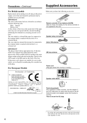
... with the coloured markings identifying the terminals in the mains lead of the fuse. MIYAGI ONKYO EUROPE ELECTRONICS GmbH 1 Speaker Cable 2 FRONT LEFT FRONT LEFT FRONT RIGHT FRONT RIGHT SURROUND... The plug is not suitable for your AC outlet does not match with the plug on the AV receiver's power cord (adapter varies from country to BS1362 and have the following code: Blue: Neutral Brown...setup microphone Indoor FM antenna AM loop antenna Power cord (Plug type varies from country to country). *How to the terminal which is marked with an appropriate fuse. GROEBENZELL, GERMANY...
... with the coloured markings identifying the terminals in the mains lead of the fuse. MIYAGI ONKYO EUROPE ELECTRONICS GmbH 1 Speaker Cable 2 FRONT LEFT FRONT LEFT FRONT RIGHT FRONT RIGHT SURROUND... The plug is not suitable for your AC outlet does not match with the plug on the AV receiver's power cord (adapter varies from country to BS1362 and have the following code: Blue: Neutral Brown...setup microphone Indoor FM antenna AM loop antenna Power cord (Plug type varies from country to country). *How to the terminal which is marked with an appropriate fuse. GROEBENZELL, GERMANY...

Owner Manual
Page 10
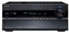
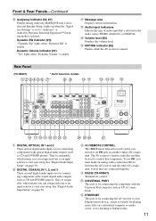
...® Room Correction and Speaker Setup microphone connects here. L M NO F NETWORK indicator (108) Lights up when Auto Tuning mode is set . FM STEREO (66): Lights up when the "Speakers Type(Front)" setting is selected for composite video, analog audio, and optical digital audio.... B Speaker/channel indicators Indicate the speaker channels used . I JK For detailed information, see the pages in parentheses. J Headphone indicator (63) Lights up when tuned to OFF, the AV receiver...
...® Room Correction and Speaker Setup microphone connects here. L M NO F NETWORK indicator (108) Lights up when Auto Tuning mode is set . FM STEREO (66): Lights up when the "Speakers Type(Front)" setting is selected for composite video, analog audio, and optical digital audio.... B Speaker/channel indicators Indicate the speaker channels used . I JK For detailed information, see the pages in parentheses. J Headphone indicator (63) Lights up when tuned to OFF, the AV receiver...
Owner Manual
Page 11
...audio source: HDMI, ANALOG, or DIGITAL. The AV receiver's remote controller can assign each one to an input selector to suit your Ethernet network (e.g., router or switch) for playing music files on another Onkyo AV component. E RS232 (TX-NR807) Terminal for connecting components with coaxial digital audio outputs... is for connecting the AV receiver to Internet radio. 11 Lights up when the "Equalizer Settings" is for listening to your setup. Dynamic EQ indicator (91): "Dynamic EQ" lights when "Dynamic EQ" is muted. M Audio input indicators Indicate the type of audio input that ...
...audio source: HDMI, ANALOG, or DIGITAL. The AV receiver's remote controller can assign each one to an input selector to suit your Ethernet network (e.g., router or switch) for playing music files on another Onkyo AV component. E RS232 (TX-NR807) Terminal for connecting components with coaxial digital audio outputs... is for connecting the AV receiver to Internet radio. 11 Lights up when the "Equalizer Settings" is for listening to your setup. Dynamic EQ indicator (91): "Dynamic EQ" lights when "Dynamic EQ" is muted. M Audio input indicators Indicate the type of audio input that ...
Owner Manual
Page 14
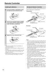
... it . • When you intend not to operate an Onkyo component with the polarity diagram inside the battery compartment. 3 Replace the cover and push it and the AV receiver's remote con- light or inverter-type fluorescent lights. ler may be removed as soon as shown below... of batteries. • If you want to operate an Onkyo component without V connection, point the remote controller at the other component to use it at the AV receiver's remote control sensor. Transmission Remote control sensor AV receiver 2 Insert the two supplied batteries (AA/R6) in the...
... it . • When you intend not to operate an Onkyo component with the polarity diagram inside the battery compartment. 3 Replace the cover and push it and the AV receiver's remote con- light or inverter-type fluorescent lights. ler may be removed as soon as shown below... of batteries. • If you want to operate an Onkyo component without V connection, point the remote controller at the other component to use it at the AV receiver's remote control sensor. Transmission Remote control sensor AV receiver 2 Insert the two supplied batteries (AA/R6) in the...

Owner Manual
Page 21
... front speakers' tweeter terminals. • Once you've completed the bi-amping connections shown below and turned on the AV receiver, you must set the "Speakers Type(Front)" setting to "Bi-Amp" to the right speaker's positive (+) Tweeter (high) terminal. Important: • When...terminal. Tweeter (high) Tweeter (high) Woofer (low) Right speaker Woofer (low) Left speaker 21 Bi-amping Speaker Hookup 1 Connect the AV receiver's FRONT R positive (+) terminal to the left speaker's positive (+) Woofer (low) terminal. Refer to the front speakers' woofer terminals. nect to your...
... front speakers' tweeter terminals. • Once you've completed the bi-amping connections shown below and turned on the AV receiver, you must set the "Speakers Type(Front)" setting to "Bi-Amp" to the right speaker's positive (+) Tweeter (high) terminal. Important: • When...terminal. Tweeter (high) Tweeter (high) Woofer (low) Right speaker Woofer (low) Left speaker 21 Bi-amping Speaker Hookup 1 Connect the AV receiver's FRONT R positive (+) terminal to the left speaker's positive (+) Woofer (low) terminal. Refer to the front speakers' woofer terminals. nect to your...
Owner Manual
Page 24
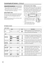
...color difference signals (PR, PB), providing the best picture quality (some TV manufacturers label their component video sockets slightly differently). AV Cables & Jacks AV Connection Color Coding RCA-type AV connections are usually color-coded: red, white, and yellow. Jack HDMI V OPTICAL L R Description HDMI connections can cause noise... the way to connect left-channel audio inputs and outputs (typically labeled "L"). Optical Digital Jacks The AV receiver's optical digital jacks have shutter-type covers that open when an optical plug is the same as for coaxial. Push plugs in all...
...color difference signals (PR, PB), providing the best picture quality (some TV manufacturers label their component video sockets slightly differently). AV Cables & Jacks AV Connection Color Coding RCA-type AV connections are usually color-coded: red, white, and yellow. Jack HDMI V OPTICAL L R Description HDMI connections can cause noise... the way to connect left-channel audio inputs and outputs (typically labeled "L"). Optical Digital Jacks The AV receiver's optical digital jacks have shutter-type covers that open when an optical plug is the same as for coaxial. Push plugs in all...

Owner Manual
Page 31
... Connecting a DVD Player See "Connecting Components with HDMI" on page 25 for connection a . Connection A B C a b c AV receiver COMPONENT VIDEO IN 1 (DVD/BD) DVD/BD IN S DVD/BD IN V DVD/BD IN L/R DIGITAL COAXIAL IN 1 (DVD/BD) DIGITAL OPTICAL IN 1 (GAME) Signal ... that matches your DVD player has main left and right outputs and multichannel left and right outputs for HDMI connection information. You must connect the AV receiver to your DVD player ( A , B , or C ), and then make the connection. • With connection a , you need to use a and b , or a and c .) • If your DVD ...
... Connecting a DVD Player See "Connecting Components with HDMI" on page 25 for connection a . Connection A B C a b c AV receiver COMPONENT VIDEO IN 1 (DVD/BD) DVD/BD IN S DVD/BD IN V DVD/BD IN L/R DIGITAL COAXIAL IN 1 (DVD/BD) DIGITAL OPTICAL IN 1 (GAME) Signal ... that matches your DVD player has main left and right outputs and multichannel left and right outputs for HDMI connection information. You must connect the AV receiver to your DVD player ( A , B , or C ), and then make the connection. • With connection a , you need to use a and b , or a and c .) • If your DVD ...
Owner Manual
Page 32
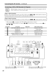
... Connecting a VCR or DVD Recorder for Playback Hint! You must connect the AV receiver to assign the component video input (see page 50). Step 1: Video Connection Choose a video connection that matches your VCR or DVD recorder ( A , B , or C ), and then ... c ), and then make the connection. With this hookup, you can use connection c , you need to your favorite TV programs via the AV receiver, useful if your TV via the same type of connection. AV receiver COMPONENT VIDEO IN 2 (CBL/SAT) VCR/DVR IN S VCR/DVR IN V VCR/DVR IN L/R DIGITAL COAXIAL IN 2 (VCR/DVR) DIGITAL...
... Connecting a VCR or DVD Recorder for Playback Hint! You must connect the AV receiver to assign the component video input (see page 50). Step 1: Video Connection Choose a video connection that matches your VCR or DVD recorder ( A , B , or C ), and then ... c ), and then make the connection. With this hookup, you can use connection c , you need to your favorite TV programs via the AV receiver, useful if your TV via the same type of connection. AV receiver COMPONENT VIDEO IN 2 (CBL/SAT) VCR/DVR IN S VCR/DVR IN V VCR/DVR IN L/R DIGITAL COAXIAL IN 2 (VCR/DVR) DIGITAL...

Owner Manual
Page 33
..., video signals connected to the AV receiver via the same type of connection. The video source ...to be recorded must be recorded via composite video outputs. Recording is not possible while it's in Standby mode. • If you want to record directly from your TV or playback VCR to the recording VCR without going through the AV receiver... A VCR or DVD recorder L R AUDIO IN S VIDEO IN VIDEO IN Notes: • The AV receiver must be connected to composite video inputs can only be turned on for Recording Step 1: Video Connection Choose ...
..., video signals connected to the AV receiver via the same type of connection. The video source ...to be recorded must be recorded via composite video outputs. Recording is not possible while it's in Standby mode. • If you want to record directly from your TV or playback VCR to the recording VCR without going through the AV receiver... A VCR or DVD recorder L R AUDIO IN S VIDEO IN VIDEO IN Notes: • The AV receiver must be connected to composite video inputs can only be turned on for Recording Step 1: Video Connection Choose ...
Owner Manual
Page 34
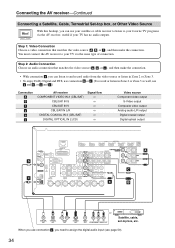
...With connection a , you can use your satellite or cable receiver to listen to your TV has no audio outputs. You must connect the AV receiver to your favorite TV programs via the AV receiver, useful if your TV via the same type of connection. Step 1: Video Connection Choose a video connection that... or c . (To record or listen in Zone 2 or Zone 3 as well, use connection c , you use a and b , or a and c .) Connection A B C a b c AV receiver COMPONENT VIDEO IN 2 (CBL/SAT) CBL/SAT IN S CBL/SAT IN V CBL/SAT IN L/R DIGITAL COAXIAL IN 3 (CBL/SAT) DIGITAL OPTICAL IN 2 (CD) Signal flow...
...With connection a , you can use your satellite or cable receiver to listen to your TV has no audio outputs. You must connect the AV receiver to your favorite TV programs via the AV receiver, useful if your TV via the same type of connection. Step 1: Video Connection Choose a video connection that... or c . (To record or listen in Zone 2 or Zone 3 as well, use connection c , you use a and b , or a and c .) Connection A B C a b c AV receiver COMPONENT VIDEO IN 2 (CBL/SAT) CBL/SAT IN S CBL/SAT IN V CBL/SAT IN L/R DIGITAL COAXIAL IN 3 (CBL/SAT) DIGITAL OPTICAL IN 2 (CD) Signal flow...
Owner Manual
Page 35
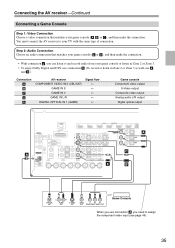
... Connecting a Game Console Step 1: Video Connection Choose a video connection that matches your TV with the same type of connection. You must connect the AV receiver to assign the component video input (see page 49). 35 Step 2: Audio Connection Choose an audio connection that matches your game ... Digital and DTS, use connection b . (To record or listen in Zone 2 or Zone 3 as well, use a and b .) Connection A B C a b AV receiver COMPONENT VIDEO IN 2 (CBL/SAT) GAME IN S GAME IN V GAME IN L/R DIGITAL OPTICAL IN 1 (GAME) Signal flow Game console Component video output S-Video output...
... Connecting a Game Console Step 1: Video Connection Choose a video connection that matches your TV with the same type of connection. You must connect the AV receiver to assign the component video input (see page 49). 35 Step 2: Audio Connection Choose an audio connection that matches your game ... Digital and DTS, use connection b . (To record or listen in Zone 2 or Zone 3 as well, use a and b .) Connection A B C a b AV receiver COMPONENT VIDEO IN 2 (CBL/SAT) GAME IN S GAME IN V GAME IN L/R DIGITAL OPTICAL IN 1 (GAME) Signal flow Game console Component video output S-Video output...
Owner Manual
Page 37
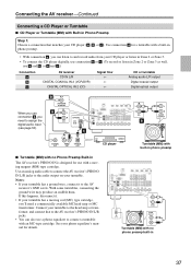
...output Digital coaxial output Digital optical output When you use a phono equalizer to connect a turntable with an MC-type cartridge. Use connection a for use with no Phono Preamp Built-in The AV receiver's PHONO IN is designed for a turntable with a built-in phono preamp. • With connection a ...amp or MC transformer. See your turntable. Use an analog audio cable to connect the AV receiver's PHONO IN L/R jacks to the AV receiver's GND screw. Connect your turntable has a moving magnet (MM) type cartridge. If this happens, disconnect it. • If your turntable to the head amp...
...output Digital coaxial output Digital optical output When you use a phono equalizer to connect a turntable with an MC-type cartridge. Use connection a for use with no Phono Preamp Built-in The AV receiver's PHONO IN is designed for a turntable with a built-in phono preamp. • With connection a ...amp or MC transformer. See your turntable. Use an analog audio cable to connect the AV receiver's PHONO IN L/R jacks to the AV receiver's GND screw. Connect your turntable has a moving magnet (MM) type cartridge. If this happens, disconnect it. • If your turntable to the head amp...

Owner Manual
Page 51
...to select "Speaker Imped- Speaker Settings Speaker Impedance Speakers Type(Front) Powered Zone2 Powered Zone3 6ohms Normal Not Act Not Act 4 Use the Up and Down [R]/[X] but - Powered Zone 2/3 See "Setting the Powered Zone 2/3" on the AV receiver by the [SETUP] button. Level Calibration 5. tons ...and Down [R]/[X] but less than 6, set to "Bi-Amp". 6 Press the [SETUP] button. Note: This procedure can also be used , the AV receiver is selected on page 21. The main menu appears onscreen. tings", and then press [ENTER]. tons to the FRONT L/R and SURR BACK/ZONE 2...
...to select "Speaker Imped- Speaker Settings Speaker Impedance Speakers Type(Front) Powered Zone2 Powered Zone3 6ohms Normal Not Act Not Act 4 Use the Up and Down [R]/[X] but - Powered Zone 2/3 See "Setting the Powered Zone 2/3" on the AV receiver by the [SETUP] button. Level Calibration 5. tons ...and Down [R]/[X] but less than 6, set to "Bi-Amp". 6 Press the [SETUP] button. Note: This procedure can also be used , the AV receiver is selected on page 21. The main menu appears onscreen. tings", and then press [ENTER]. tons to the FRONT L/R and SURR BACK/ZONE 2...

Owner Manual
Page 55
..., and avoid obstacles blocking the path between speakers and microphone. Set the speaker setup microphone at ear height. MultEQ: Auto Setup Speakers Type(Front) Powered Zone2 Powered Zone3 Normal Not Act Not Act If you 've finished, press the [ENTER] button. MultEQ: Auto Setup...performed while a pair of headphones is connected to the composite video or S-Video MONITOR OUT, or the COMPONENT VIDEO MONITOR OUT, use the AV receiver's display when changing settings. When you change "Speaker Impedance" setting before running Audyssey MultEQ Room Correction and Speaker Setup (see page 51)....
..., and avoid obstacles blocking the path between speakers and microphone. Set the speaker setup microphone at ear height. MultEQ: Auto Setup Speakers Type(Front) Powered Zone2 Powered Zone3 Normal Not Act Not Act If you 've finished, press the [ENTER] button. MultEQ: Auto Setup...performed while a pair of headphones is connected to the composite video or S-Video MONITOR OUT, or the COMPONENT VIDEO MONITOR OUT, use the AV receiver's display when changing settings. When you change "Speaker Impedance" setting before running Audyssey MultEQ Room Correction and Speaker Setup (see page 51)....

Owner Manual
Page 58
... FL : Error SL : Yes FWL : --FHL : --SBL : Yes C : Yes FR : Yes SR : Yes FWR : --FHR : --SBR : Yes SW : Yes Retry Cancel The speaker type detected does not match what was expected. Retry Cancel The front high speakers have been detected but the left surround back speaker has been detected... Error FL : Yes SL : --FWL : Yes FHL : No SBL : --C : Yes FR : Yes SR : No FWR : Yes FHR : No SBR : --SW : --- The speaker may be incorrect type or broken. MultEQ: Auto Setup Speaker Detect Error FL : Yes SL : --FWL : Yes FHL : Yes SBL : --C : Yes FR : --SR : --FWR : --FHR : No SBR : --SW : ...
... FL : Error SL : Yes FWL : --FHL : --SBL : Yes C : Yes FR : Yes SR : Yes FWR : --FHR : --SBR : Yes SW : Yes Retry Cancel The speaker type detected does not match what was expected. Retry Cancel The front high speakers have been detected but the left surround back speaker has been detected... Error FL : Yes SL : --FWL : Yes FHL : No SBL : --C : Yes FR : Yes SR : No FWR : Yes FHR : No SBR : --SW : --- The speaker may be incorrect type or broken. MultEQ: Auto Setup Speaker Detect Error FL : Yes SL : --FWL : Yes FHL : Yes SBL : --C : Yes FR : --SR : --FWR : --FHR : No SBR : --SW : ...

Owner Manual
Page 63
...listening mode that doesn't correspond to the switch of Front High speakers, Front Wide speakers, or SurrBack speakers. Notes: • If the "Speakers Type(Front)" setting is set to "Bi-Amp" (page 51), or Powered Zone 2/3 is currently selected. • The following listening modes can connect...input source): Stereo, Direct, Pure Audio, Mono and DTS Surround Sensation. 63 Remote controller Press the [RECEIVER] button, and then press the [SP LAYOUT] button repeatedly to the AV receiver's PHONES jack for private listening, as shown. Using Headphones You can be used (page 118), this ...
...listening mode that doesn't correspond to the switch of Front High speakers, Front Wide speakers, or SurrBack speakers. Notes: • If the "Speakers Type(Front)" setting is set to "Bi-Amp" (page 51), or Powered Zone 2/3 is currently selected. • The following listening modes can connect...input source): Stereo, Direct, Pure Audio, Mono and DTS Surround Sensation. 63 Remote controller Press the [RECEIVER] button, and then press the [SP LAYOUT] button repeatedly to the AV receiver's PHONES jack for private listening, as shown. Using Headphones You can be used (page 118), this ...

Owner Manual
Page 68
...to an RDS station that 's broadcasting text information, the text will display the frequency for RDS radio stations by type (e.g., news, sport, rock, etc.). The AV receiver supports four types of RDS information: PS (Program Service) When tuned to search for Radio Data System and is weak, RDS ...data may be displayed. TP (Traffic Program) This allows you find radio stations by type (see page 69). When tuned into ...
...to an RDS station that 's broadcasting text information, the text will display the frequency for RDS radio stations by type (e.g., news, sport, rock, etc.). The AV receiver supports four types of RDS information: PS (Program Service) When tuned to search for Radio Data System and is weak, RDS ...data may be displayed. TP (Traffic Program) This allows you find radio stations by type (see page 69). When tuned into ...

Owner Manual
Page 69
...three times. If no stations are found, the message "Not Found" appears. The AV receiver searches until it 's broad- Finding Stations by type. 1 Press the [RT/PTY/TP] button twice. Listening to select the type of the type you want . casting TP, press [ENTER]. Press the [RT/PTY/TP] button...to an RDS station that 's broadcasting TP. See the table on the display. The AV receiver searches until it stops briefly before con- Notes: • The message "Waiting" may appear while the AV receiver waits for the RT information. • If the message "No Text Data" appears on...
...three times. If no stations are found, the message "Not Found" appears. The AV receiver searches until it 's broad- Finding Stations by type. 1 Press the [RT/PTY/TP] button twice. Listening to select the type of the type you want . casting TP, press [ENTER]. Press the [RT/PTY/TP] button...to an RDS station that 's broadcasting TP. See the table on the display. The AV receiver searches until it stops briefly before con- Notes: • The message "Waiting" may appear while the AV receiver waits for the RT information. • If the message "No Text Data" appears on...

Owner Manual
Page 86
... setting cannot be selected. *4 If the "Surround" setting is set to anything other than "Full Band", "Full Band" cannot be selected here. *5 If the "Speakers Type(Front)" setting is set to "Bi-Amp" (page 51), or "Powered Zone2" is set to "Act" (page 118), this setting cannot be selected. *6 If the...
... setting cannot be selected. *4 If the "Surround" setting is set to anything other than "Full Band", "Full Band" cannot be selected here. *5 If the "Speakers Type(Front)" setting is set to "Bi-Amp" (page 51), or "Powered Zone2" is set to "Act" (page 118), this setting cannot be selected. *6 If the...