User Manual
Page 6
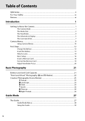
Table of Contents Q&A Index ...ii For Your Safety ...ix Notices...xi Introduction 1 Getting to Know the Camera 1 The Camera Body ...1 The Mode Dial...3 The Viewfinder...4 The Information Display...5 The Command Dial ...7 Camera Menus...9 Using Camera Menus ...10 First Steps ...12 Charge the Battery ...12 Insert ...
Table of Contents Q&A Index ...ii For Your Safety ...ix Notices...xi Introduction 1 Getting to Know the Camera 1 The Camera Body ...1 The Mode Dial...3 The Viewfinder...4 The Information Display...5 The Command Dial ...7 Camera Menus...9 Using Camera Menus ...10 First Steps ...12 Charge the Battery ...12 Insert ...
User Manual
Page 17
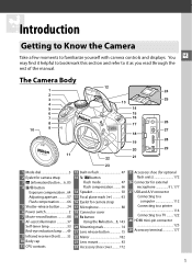
You X may find it as you read through the rest of the manual. The Camera Body 1 2 3 4 5 6 7 8 10 9 12 24 25 13 14 15 16 17 26 27 18 28 19 20 29 11 22 21 23 1 Mode dial 3 2 Eyelet for camera ............24 6 Power switch 2 7 Movie-record button 88 8 AF-assist illuminator 37 Self-timer lamp 33 Red-eye reduction lamp ......49 9 Infrared receiver (front)........ 33 10 Body cap 11 CPU contacts 12 Built-in flash 47 13 M/ Y button Flash mode 47 Flash compensation ......... 66 14 Speaker 92 15 Focal plane mark (E 43...
You X may find it as you read through the rest of the manual. The Camera Body 1 2 3 4 5 6 7 8 10 9 12 24 25 13 14 15 16 17 26 27 18 28 19 20 29 11 22 21 23 1 Mode dial 3 2 Eyelet for camera ............24 6 Power switch 2 7 Movie-record button 88 8 AF-assist illuminator 37 Self-timer lamp 33 Red-eye reduction lamp ......49 9 Infrared receiver (front)........ 33 10 Body cap 11 CPU contacts 12 Built-in flash 47 13 M/ Y button Flash mode 47 Flash compensation ......... 66 14 Speaker 92 15 Focal plane mark (E 43...
User Manual
Page 18
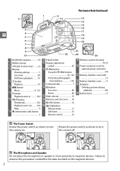
... 24 Battery latch 13 A The Power Switch Rotate the power switch as shown to observe this precaution could affect the data recorded on . The Camera Body (Continued) 2 3 X 4 5 6 7 8 9 10 1 11 12 13 14 15 16 17 18 19 20 21 23 22 24 1 Viewfinder eyepiece 34 2 Rubber eyecup 3 Infrared receiver (rear) .........33...
... 24 Battery latch 13 A The Power Switch Rotate the power switch as shown to observe this precaution could affect the data recorded on . The Camera Body (Continued) 2 3 X 4 5 6 7 8 9 10 1 11 12 13 14 15 16 17 18 19 20 21 23 22 24 1 Viewfinder eyepiece 34 2 Rubber eyecup 3 Infrared receiver (rear) .........33...
User Manual
Page 30
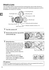
... ring (0 24) A-M mode switch (see below) Vibration reduction switch (0 15) 1 Turn the camera off. 2 Remove the rear lens cap and the camera body cap. 3 Attach the lens. Autofocus is removed. Being careful not to A (autofocus; Keeping the mounting mark on the lens aligned with the mounting mark on... the camera body, position the lens in this manual for autofocus with manual override). The lens generally used in the camera's bayonet mount (q). if the lens...
... ring (0 24) A-M mode switch (see below) Vibration reduction switch (0 15) 1 Turn the camera off. 2 Remove the rear lens cap and the camera body cap. 3 Attach the lens. Autofocus is removed. Being careful not to A (autofocus; Keeping the mounting mark on the lens aligned with the mounting mark on... the camera body, position the lens in this manual for autofocus with manual override). The lens generally used in the camera's bayonet mount (q). if the lens...
User Manual
Page 31
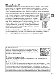
... Do not turn the camera off when the camera is securely mounted on the image in the viewfinder and simplifying the process of 55 mm (Nikon measurements; If power to the lens is cut while vibration reduction is panned horizontally, for the image in the viewfinder may rattle when shaken. ... turning the camera on if the tripod head is not secured or when using a monopod. After removing the lens, replace the lens caps and camera body cap. effects vary with an aperture ring (0 168), lock aperture at a focal length of framing the subject and focusing in a wide arc. When vibration...
... Do not turn the camera off when the camera is securely mounted on the image in the viewfinder and simplifying the process of 55 mm (Nikon measurements; If power to the lens is cut while vibration reduction is panned horizontally, for the image in the viewfinder may rattle when shaken. ... turning the camera on if the tripod head is not secured or when using a monopod. After removing the lens, replace the lens caps and camera body cap. effects vary with an aperture ring (0 168), lock aperture at a focal length of framing the subject and focusing in a wide arc. When vibration...
User Manual
Page 38
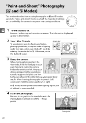
... When framing photographs in the viewfinder, hold the camera as shown at least one foot half a pace ahead of the other to keep your upper body stable. In j mode, shutter speeds slow when lighting is recommended. 4 Frame the photograph. use of a flash is prohibited, photograph infants, or .... 1 s Turn the camera on . When framing photographs in portrait (tall) orientation, hold the handgrip in your right hand and cradle the camera body or lens with the main subject in at right. Otherwise, rotate the dial to i (auto). Keep your elbows propped lightly against your left. The...
... When framing photographs in the viewfinder, hold the camera as shown at least one foot half a pace ahead of the other to keep your upper body stable. In j mode, shutter speeds slow when lighting is recommended. 4 Frame the photograph. use of a flash is prohibited, photograph infants, or .... 1 s Turn the camera on . When framing photographs in portrait (tall) orientation, hold the handgrip in your right hand and cradle the camera body or lens with the main subject in at right. Otherwise, rotate the dial to i (auto). Keep your elbows propped lightly against your left. The...

User Manual
Page 59
... If the lens supports M/A (autofocus with the lens. The distance between your subject and the camera, measure from the focal plane mark on the camera body. A Focal Plane Position To determine the distance between the lens mounting flange and the focal plane is in front of the mode selected with manual...
... If the lens supports M/A (autofocus with the lens. The distance between your subject and the camera, measure from the focal plane mark on the camera body. A Focal Plane Position To determine the distance between the lens mounting flange and the focal plane is in front of the mode selected with manual...
User Manual
Page 193
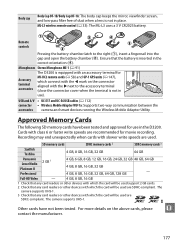
...been tested and approved for movie recording. Microphones Stereo Microphone ME-1 (0 91) Accessory terminal accessories The D3200 is equipped with an accessory terminal for MC-DC2 remote cords (0 58) and GP-1 GPS units .... The camera supports UHS-1. 3 Check that the battery is not in use in the D3200. Remote controls Pressing the battery-chamber latch to the accessory terminal (close the connector cover ...GB 4 GB, 8 GB, 16 GB, 32 GB, 64 GB, 128 GB - Body cap Body Cap BF-1B/Body Cap BF-1A: The body cap keeps the mirror, viewfinder screen, and low-pass filter free of dust when a ...
...been tested and approved for movie recording. Microphones Stereo Microphone ME-1 (0 91) Accessory terminal accessories The D3200 is equipped with an accessory terminal for MC-DC2 remote cords (0 58) and GP-1 GPS units .... The camera supports UHS-1. 3 Check that the battery is not in use in the D3200. Remote controls Pressing the battery-chamber latch to the accessory terminal (close the connector cover ...GB 4 GB, 8 GB, 16 GB, 32 GB, 64 GB, 128 GB - Body cap Body Cap BF-1B/Body Cap BF-1A: The body cap keeps the mirror, viewfinder screen, and low-pass filter free of dust when a ...

User Manual
Page 195
... flash units, should be included when the camera is a precision device and requires regular servicing. Remove dust and lint with a cloth lightly body dampened in place. D Servicing the Camera and Accessories The camera is inspected or serviced. 179 Important: Dust or other volatile chemicals. Do ... dust and lint, then wipe gently with the terminal cover in distilled water and dry thoroughly. Nikon recommends that the n camera be inspected by the original retailer or Nikon-authorized service representative once every one to two years, and that it be serviced once every three...
... flash units, should be included when the camera is a precision device and requires regular servicing. Remove dust and lint with a cloth lightly body dampened in place. D Servicing the Camera and Accessories The camera is inspected or serviced. 179 Important: Dust or other volatile chemicals. Do ... dust and lint, then wipe gently with the terminal cover in distilled water and dry thoroughly. Nikon recommends that the n camera be inspected by the original retailer or Nikon-authorized service representative once every one to two years, and that it be serviced once every three...
User Manual
Page 199
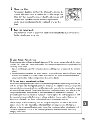
...body cap. Should foreign matter find its way onto the low-pass filter, clean the filter as the bristles could damage the filter. Dirt that may be adhering to first remove all dust and other foreign matter that can not be removed with a blower. Photographs n affected by authorized Nikon...precaution to the low-pass filter, where it may enter the camera when lenses are removed or exchanged. End cleaning or inspection immediately. The D3200, however, is delicate and easily damaged. 7 Clean the filter. Remove any dust and lint from coming into contact with interchangeable lenses, ...
...body cap. Should foreign matter find its way onto the low-pass filter, clean the filter as the bristles could damage the filter. Dirt that may be adhering to first remove all dust and other foreign matter that can not be removed with a blower. Photographs n affected by authorized Nikon...precaution to the low-pass filter, where it may enter the camera when lenses are removed or exchanged. End cleaning or inspection immediately. The D3200, however, is delicate and easily damaged. 7 Clean the filter. Remove any dust and lint from coming into contact with interchangeable lenses, ...

User Manual
Page 200
... internal circuitry. The lens and mirror are being recorded or deleted. These actions could scratch, deform, or tear the curtain. Cleaning: When cleaning the camera body, use or store this device in water or exposed to another while the AC adapter is on the curtain, poke it with a blower. Turn the...
... internal circuitry. The lens and mirror are being recorded or deleted. These actions could scratch, deform, or tear the curtain. Cleaning: When cleaning the camera body, use or store this device in water or exposed to another while the AC adapter is on the curtain, poke it with a blower. Turn the...
User Manual
Page 216
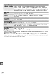
... 1222) Dimensions/weight Dimensions (W × H × D) Approx. 125 × 96 × 76.5 mm (5.0 × 3.8 × 3.1 in this manual may result from any time and without body cap; Nikon will not be held liable for a camera with a fully-charged battery operating at any mistakes that may contain. approx. 455 g/1 lb (camera...
... 1222) Dimensions/weight Dimensions (W × H × D) Approx. 125 × 96 × 76.5 mm (5.0 × 3.8 × 3.1 in this manual may result from any time and without body cap; Nikon will not be held liable for a camera with a fully-charged battery operating at any mistakes that may contain. approx. 455 g/1 lb (camera...
User Manual
Page 222
...-83 Auto-servo AF 35 Available settings 187 B Battery 12, 13 Beep 141 Bit rate 90 Black-and-white 152 Blue intensifier (Filter effects) ..153 Body cap 1, 14, 177 Border (PictBridge 116 Built-in AF-assist illuminator ..... 37, 131, 171 Built-in flash 47, 132, 170 Bulb 58 Buttons 143 C Calendar...
...-83 Auto-servo AF 35 Available settings 187 B Battery 12, 13 Beep 141 Bit rate 90 Black-and-white 152 Blue intensifier (Filter effects) ..153 Body cap 1, 14, 177 Border (PictBridge 116 Built-in AF-assist illuminator ..... 37, 131, 171 Built-in flash 47, 132, 170 Bulb 58 Buttons 143 C Calendar...


