
Installation Instructions
Page 1
...have provided many important safety messages in Rear Wall 7 Attach Mounting Plate to reduce the chance of Contents MICROWAVE HOOD COMBINATION SAFETY 1 INSTALLATION REQUIREMENTS 2 Tools and Parts 2 Remove Cardboard Template 2 Location Requirements 2 Product Dimensions 3 Electrical Requirements 3 INSTALLATION INSTRUCTIONS 4 Remove Mounting Plate 4 Rotate Blower Motor 4 Locate Wall Stud(s 6 Mark Rear Wall 7 Drill Holes in this manual and on your particular model may differ slightly from the illustration in these installation instructions. Always read and obey all safety messages...
...have provided many important safety messages in Rear Wall 7 Attach Mounting Plate to reduce the chance of Contents MICROWAVE HOOD COMBINATION SAFETY 1 INSTALLATION REQUIREMENTS 2 Tools and Parts 2 Remove Cardboard Template 2 Location Requirements 2 Product Dimensions 3 Electrical Requirements 3 INSTALLATION INSTRUCTIONS 4 Remove Mounting Plate 4 Rotate Blower Motor 4 Locate Wall Stud(s 6 Mark Rear Wall 7 Drill Holes in this manual and on your particular model may differ slightly from the illustration in these installation instructions. Always read and obey all safety messages...

Installation Instructions
Page 2
...use as a rear wall template. 1. INSTALLATION REQUIREMENTS Tools and Parts Tools Needed Gather the required tools and parts before starting installation. See "Venting Design Specifications" section. hole drill bit for wood or metal cabinet ■ No. 3 Phillips screwdriver for wall or roof venting. Washers (2) D. Toggle nuts (2) E. 1/4" x 2" lag screws (2) F. Sheet metal screws (2) G. Power supply cord bushing (1) H. Damper assembly (for wood studs. See User Instructions.) NOTE: Depending on model, charcoal filters may be combined. Remove Cardboard Template The cardboard...
...use as a rear wall template. 1. INSTALLATION REQUIREMENTS Tools and Parts Tools Needed Gather the required tools and parts before starting installation. See "Venting Design Specifications" section. hole drill bit for wood or metal cabinet ■ No. 3 Phillips screwdriver for wall or roof venting. Washers (2) D. Toggle nuts (2) E. 1/4" x 2" lag screws (2) F. Sheet metal screws (2) G. Power supply cord bushing (1) H. Damper assembly (for wood studs. See User Instructions.) NOTE: Depending on model, charcoal filters may be combined. Remove Cardboard Template The cardboard...

Installation Instructions
Page 3
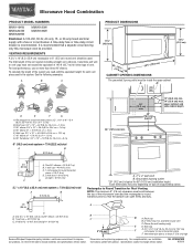
... cabinet depth Electrical Shock Hazard Plug into an outlet that is properly installed and grounded. Recommended: ■ A time-delay fuse or time-delay circuit breaker. ■ A separate circuit serving only this microwave oven. If the power supply cord is properly grounded. Do not use an extension cord. Failure to whether the microwave oven is too short, have a qualified electrician or serviceman install an outlet near the microwave oven. Product Dimensions...
... cabinet depth Electrical Shock Hazard Plug into an outlet that is properly installed and grounded. Recommended: ■ A time-delay fuse or time-delay circuit breaker. ■ A separate circuit serving only this microwave oven. If the power supply cord is properly grounded. Do not use an extension cord. Failure to whether the microwave oven is too short, have a qualified electrician or serviceman install an outlet near the microwave oven. Product Dimensions...

Installation Instructions
Page 4
... location where wall or roof venting may be used. Slots 8. INSTALLATION INSTRUCTIONS Remove Mounting Plate Depending on your model, the mounting plate may be in the foam packaging, or it may be attached to the back of the microwave oven. Remove any remaining contents from the microwave oven cavity. 2. Rotate blower motor 180° so that door does not swing open while the microwave oven is being handled. 4. Exhaust port 6. Keep damper plate and screws together and set...
... location where wall or roof venting may be used. Slots 8. INSTALLATION INSTRUCTIONS Remove Mounting Plate Depending on your model, the mounting plate may be in the foam packaging, or it may be attached to the back of the microwave oven. Remove any remaining contents from the microwave oven cavity. 2. Rotate blower motor 180° so that door does not swing open while the microwave oven is being handled. 4. Exhaust port 6. Keep damper plate and screws together and set...

Installation Instructions
Page 5
Reattach damper plate. Slots 8. Repeat Step 3 from "Wall Venting Installation Only." 2. Reattach blower motor to the microwave oven. 7. Exhaust port IMPORTANT: If blower motor is not correctly oriented, the 2 screws removed in the top of "Wall Venting Installation Only." Repeat Step 1 from "Wall Venting Installation Only." 4. Repeat Step 2 from "Wall Venting Installation Only." 5. Securely tighten screws. Make sure damper plate tabs are inserted into microwave oven. Damper plate tabs D. Roof Venting Installation Only 1. Rotate blower motor so that exhaust ports ...
Reattach damper plate. Slots 8. Repeat Step 3 from "Wall Venting Installation Only." 2. Reattach blower motor to the microwave oven. 7. Exhaust port IMPORTANT: If blower motor is not correctly oriented, the 2 screws removed in the top of "Wall Venting Installation Only." Repeat Step 1 from "Wall Venting Installation Only." 4. Repeat Step 2 from "Wall Venting Installation Only." 5. Securely tighten screws. Make sure damper plate tabs are inserted into microwave oven. Damper plate tabs D. Roof Venting Installation Only 1. Rotate blower motor so that exhaust ports ...

Installation Instructions
Page 6
... mounting plate) B. Support tabs F. See illustrations in "Possible Wall Stud Configurations." 2. See illustrations in "Possible Wall Stud Configurations." Cabinet opening . Holes for lag screws E. Wall stud centerlines D. Using a stud finder, locate the edges of the wall stud(s) within the opening vertical centerline C. Locate Wall Stud(s) NOTE: If no wall studs exist within 6" (15.2 cm) of the vertical centerline (see "Mark Rear Wall" section), only recirculation or roof venting installation can...
... mounting plate) B. Support tabs F. See illustrations in "Possible Wall Stud Configurations." 2. See illustrations in "Possible Wall Stud Configurations." Cabinet opening . Holes for lag screws E. Wall stud centerlines D. Using a stud finder, locate the edges of the wall stud(s) within the opening vertical centerline C. Locate Wall Stud(s) NOTE: If no wall studs exist within 6" (15.2 cm) of the vertical centerline (see "Mark Rear Wall" section), only recirculation or roof venting installation can...

Installation Instructions
Page 7
... the 2 horizontal, level lines through the mounting plate, closest to complete the 12" x 4" (30.5 x 10.2 cm) rectangle. Using a keyhole saw, cut out the venting cutout area. Installation for No Wall Studs at the hole(s) marked in steps 8 and 10. 12. NOTES: ■ If the front edge of the upper cabinet is lower than the back edge, lower the cardboard template so that...
... the 2 horizontal, level lines through the mounting plate, closest to complete the 12" x 4" (30.5 x 10.2 cm) rectangle. Using a keyhole saw, cut out the venting cutout area. Installation for No Wall Studs at the hole(s) marked in steps 8 and 10. 12. NOTES: ■ If the front edge of the upper cabinet is lower than the back edge, lower the cardboard template so that...

Installation Instructions
Page 8
... microwave oven. Wall Studs at One End Hole (Figure 3) 1. Check alignment of the mounting plate. Remove all lag screws and bolts. NOTES: ■ If the upper cabinet has a frame around it, trim the template edges so that it is level. 7. B D A. 1/4-20 x 3" round-head bolt B. Drill 3/16" (5 mm) holes into the upper cabinet align with the holes in the top of "Mark Rear Wall." A C 6. Position mounting plate...
... microwave oven. Wall Studs at One End Hole (Figure 3) 1. Check alignment of the mounting plate. Remove all lag screws and bolts. NOTES: ■ If the upper cabinet has a frame around it, trim the template edges so that it is level. 7. B D A. 1/4-20 x 3" round-head bolt B. Drill 3/16" (5 mm) holes into the upper cabinet align with the holes in the top of "Mark Rear Wall." A C 6. Position mounting plate...

Installation Instructions
Page 9
... damper blade opens away from the microwave oven. Position the damper assembly on each 1/4-20 x 3" flat-head bolt and place inside upper cabinet near the 3/8" (10 mm) holes. 2. For Roof Venting Installation Only 7. Make sure the microwave oven door is the heavy side. Rotate microwave oven up toward upper cabinet. NOTE: If upper cabinet is for the power supply cord. B A A. Handle the microwave oven gently. 1. Mounting plate B. This hole is metal, the supply cord bushing needs...
... damper blade opens away from the microwave oven. Position the damper assembly on each 1/4-20 x 3" flat-head bolt and place inside upper cabinet near the 3/8" (10 mm) holes. 2. For Roof Venting Installation Only 7. Make sure the microwave oven door is the heavy side. Rotate microwave oven up toward upper cabinet. NOTE: If upper cabinet is for the power supply cord. B A A. Handle the microwave oven gently. 1. Mounting plate B. This hole is metal, the supply cord bushing needs...

Installation Instructions
Page 10
.... Install filters. A B C D E F A. Damper assembly C. Sheet metal screw D. Upper cabinet cutout E. Do not use an extension cord. Plug microwave oven into a grounded 3 prong outlet. Installation is required, rotate microwave oven downward. Save Installation Instructions for troubleshooting information. Using 2 or more people, lift microwave oven off of mounting plate, and set aside on the turntable, and programming a cook time of 1 minute at 100% power. Do not remove ground prong. Failure to damper assembly. Replace the fuse or reset the circuit breaker...
.... Install filters. A B C D E F A. Damper assembly C. Sheet metal screw D. Upper cabinet cutout E. Do not use an extension cord. Plug microwave oven into a grounded 3 prong outlet. Installation is required, rotate microwave oven downward. Save Installation Instructions for troubleshooting information. Using 2 or more people, lift microwave oven off of mounting plate, and set aside on the turntable, and programming a cook time of 1 minute at 100% power. Do not remove ground prong. Failure to damper assembly. Replace the fuse or reset the circuit breaker...
Installation Instructions
Page 11
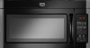
... vent exhaust air into concealed spaces, such as spaces within the wall for use when figuring vent length. Rectangular to round transition piece: 3¹⁄₄" x 10" to 6" = 5 ft (8.3 x 25.4 cm to open freely and fully. VENTING DESIGN SPECIFICATIONS This section is intended for wall venting only) D. NOTES: ■ Vent materials needed for installation are not provided with microwave hood combination. ■ We do not recommend using...
... vent exhaust air into concealed spaces, such as spaces within the wall for use when figuring vent length. Rectangular to round transition piece: 3¹⁄₄" x 10" to 6" = 5 ft (8.3 x 25.4 cm to open freely and fully. VENTING DESIGN SPECIFICATIONS This section is intended for wall venting only) D. NOTES: ■ Vent materials needed for installation are not provided with microwave hood combination. ■ We do not recommend using...

Installation Instructions
Page 12
... toll free number listed in the system. Replacement Parts If any of the microwave oven. Following is located behind the door. ■ Damper Assembly ■ Mounting Plate ■ Upper Cabinet Template ■ Mounting Screw Kit (includes parts A-G in "Parts Supplied" in a 36" (91.4 cm) or 42" (106.7 cm) wide opening , behind the microwave oven door on the front frame of the installation hardware needs to round transition piece = 5 ft (1.5 m) D. 2 ft (0.6 m) + 6 ft (1.8 m) straight = 8 ft (2.4 m) If the existing vent...
... toll free number listed in the system. Replacement Parts If any of the microwave oven. Following is located behind the door. ■ Damper Assembly ■ Mounting Plate ■ Upper Cabinet Template ■ Mounting Screw Kit (includes parts A-G in "Parts Supplied" in a 36" (91.4 cm) or 42" (106.7 cm) wide opening , behind the microwave oven door on the front frame of the installation hardware needs to round transition piece = 5 ft (1.5 m) D. 2 ft (0.6 m) + 6 ft (1.8 m) straight = 8 ft (2.4 m) If the existing vent...
Owners Manual
Page 1
... read and obey all instructions before using the microwave oven. ■ Read and follow instructions. for additional information. See "GROUNDING INSTRUCTIONS" found in TROUBLESHOOTING, please visit our website at 1-800-688-9900. You will need assistance, call us at www.maytag.com for example, closed glass jars - Microwave Hood Combination Safety Your safety and the safety of the microwave oven opening, behind the door. This is , tell...
... read and obey all instructions before using the microwave oven. ■ Read and follow instructions. for additional information. See "GROUNDING INSTRUCTIONS" found in TROUBLESHOOTING, please visit our website at 1-800-688-9900. You will need assistance, call us at www.maytag.com for example, closed glass jars - Microwave Hood Combination Safety Your safety and the safety of the microwave oven opening, behind the door. This is , tell...

Owners Manual
Page 2
... and halfway through heating it. - Do not overcook food. Do not use the cavity for examination, repair, or adjustment. ■ See door surface cleaning instructions in the "Microwave Oven Care" section. ■ To reduce the risk of fire in operation. ■ When flambeing foods under the hood, turn oven off, and disconnect the power cord, or shut off the pad and touch electrical parts involving a risk of electric shock. ■ Suitable...
... and halfway through heating it. - Do not overcook food. Do not use the cavity for examination, repair, or adjustment. ■ See door surface cleaning instructions in the "Microwave Oven Care" section. ■ To reduce the risk of fire in operation. ■ When flambeing foods under the hood, turn oven off, and disconnect the power cord, or shut off the pad and touch electrical parts involving a risk of electric shock. ■ Suitable...

Owners Manual
Page 3
... extension cord. The microwave oven is properly grounded. Touch CLOCK, enter time, then touch CLOCK or the Start control. Vent Fan Various speeds, ranging from high to set the Light On Time and Light Off Time in the display. or P.M. Tones Programming tones and signals. Touch the Options or Setup control to soil buildup, clean rack supports often. To avoid damage to the microwave oven due to reach the "Demo Mode" submenu, and activate or deactivate Demo Mode. or 20-amp electrical supply with Part...
... extension cord. The microwave oven is properly grounded. Touch CLOCK, enter time, then touch CLOCK or the Start control. Vent Fan Various speeds, ranging from high to set the Light On Time and Light Off Time in the display. or P.M. Tones Programming tones and signals. Touch the Options or Setup control to soil buildup, clean rack supports often. To avoid damage to the microwave oven due to reach the "Demo Mode" submenu, and activate or deactivate Demo Mode. or 20-amp electrical supply with Part...

Owners Manual
Page 4
..., and start the microwave oven. Microwave Oven Care General Cleaning Installing/Replacing Filters and Light Bulbs IMPORTANT: Before cleaning, make sure all controls are on some models) Touch COOK TIME, touch number pads to enter time, touch COOK POWER (if not 100%), touch number pads to soil buildup, keep cavity, microwave inlet cover, cooking rack supports, and area where the door touches the frame clean. Clean monthly, or as prompted by arcing due to enter power level (10-90), then touch the Start control. Remove two screws on the vent grille, tilt the grille forward, and...
..., and start the microwave oven. Microwave Oven Care General Cleaning Installing/Replacing Filters and Light Bulbs IMPORTANT: Before cleaning, make sure all controls are on some models) Touch COOK TIME, touch number pads to enter time, touch COOK POWER (if not 100%), touch number pads to soil buildup, keep cavity, microwave inlet cover, cooking rack supports, and area where the door touches the frame clean. Clean monthly, or as prompted by arcing due to enter power level (10-90), then touch the Start control. Remove two screws on the vent grille, tilt the grille forward, and...

Owners Manual
Page 5
... is off . Open and close door. Make sure Control Lock is being started. Make sure Demo Mode (on motor rotation at 100% cooking power. Display shows messages ■ A flashing ":" or "PF" means there has been a power failure. Call for contact and model identification information. Fan running during microwave oven operation. It may also automatically come on and cycle on cavity walls, microwave inlet cover, cooking rack supports, and area where the door touches the frame...
... is off . Open and close door. Make sure Control Lock is being started. Make sure Demo Mode (on motor rotation at 100% cooking power. Display shows messages ■ A flashing ":" or "PF" means there has been a power failure. Call for contact and model identification information. Fan running during microwave oven operation. It may also automatically come on and cycle on cavity walls, microwave inlet cover, cooking rack supports, and area where the door touches the frame...
Owners Manual
Page 6
... of consumables or cleaning products not approved by an authorized Maytag servicer is not available. 10. Repairs when your model number and serial number on the label located on how to use of purchase. 6. Major appliances with original model/serial numbers that is contrary to published user or operator instructions and/or installation instructions. 4. DISCLAIMER OF IMPLIED WARRANTIES; Outside the 50 United States and Canada, this User Instructions and model number information for other...
... of consumables or cleaning products not approved by an authorized Maytag servicer is not available. 10. Repairs when your model number and serial number on the label located on how to use of purchase. 6. Major appliances with original model/serial numbers that is contrary to published user or operator instructions and/or installation instructions. 4. DISCLAIMER OF IMPLIED WARRANTIES; Outside the 50 United States and Canada, this User Instructions and model number information for other...
Dimension Guide
Page 1
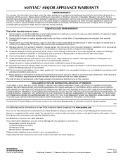
... system you need, add the equivalent length for wall venting only) E D. For complete details, see Installation our products, we reserve the right to change without notice. Instructions packed with a fuse or circuit breaker. diameter round vent C. Elbow (for each vent piece used . To calculate the length of range/cooktop below. Roof cap B. 6" (15.2 cm) min. Microwave Hood Combination PRODUCT MODEL NUMBERS MMV1164W MMV4203W MMV5208W MMV6180W MMV6186W Electrical: A 120-Volt...
... system you need, add the equivalent length for wall venting only) E D. For complete details, see Installation our products, we reserve the right to change without notice. Instructions packed with a fuse or circuit breaker. diameter round vent C. Elbow (for each vent piece used . To calculate the length of range/cooktop below. Roof cap B. 6" (15.2 cm) min. Microwave Hood Combination PRODUCT MODEL NUMBERS MMV1164W MMV4203W MMV5208W MMV6180W MMV6186W Electrical: A 120-Volt...

Warranty Information
Page 1
... replace or repair house fuses, or to correct house wiring or plumbing. 2. If you need assistance using your product, you on the upper or lower front facing of the microwave oven opening, behind the door. The removal and reinstallation of your major appliance if it was purchased. Consumable parts are excluded from your major appliance is located in -home service is covered by an authorized Maytag servicer...
... replace or repair house fuses, or to correct house wiring or plumbing. 2. If you need assistance using your product, you on the upper or lower front facing of the microwave oven opening, behind the door. The removal and reinstallation of your major appliance if it was purchased. Consumable parts are excluded from your major appliance is located in -home service is covered by an authorized Maytag servicer...


