Installation Guide
Page 1
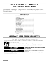
...) wide. These installation instructions cover different models. Table of Contents MICROWAVE HOOD COMBINATION SAFETY 1 INSTALLATION REQUIREMENTS 2 Tools and Parts 2 Remove Cardboard Template 2 Location Requirements 2 Product Dimensions 3 Electrical Requirements 3 INSTALLATION INSTRUCTIONS 4 Remove Mounting Plate 4 Rotate Blower Motor 4 Locate Wall Stud(s 6 Mark Rear Wall 7 Drill Holes in this manual and on your particular...
...) wide. These installation instructions cover different models. Table of Contents MICROWAVE HOOD COMBINATION SAFETY 1 INSTALLATION REQUIREMENTS 2 Tools and Parts 2 Remove Cardboard Template 2 Location Requirements 2 Product Dimensions 3 Electrical Requirements 3 INSTALLATION INSTRUCTIONS 4 Remove Mounting Plate 4 Rotate Blower Motor 4 Locate Wall Stud(s 6 Mark Rear Wall 7 Drill Holes in this manual and on your particular...
Installation Guide
Page 2
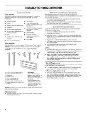
...items placed inside the microwave oven and upper cabinet. ■ Grounded electrical outlet inside the perforation is for wood studs. See "Installation Dimensions" illustration. ■ Minimum one 2" x 4" (50.8 x 101.6 mm) wood wall stud and minimum 3/8" (10 mm) ...Needed Gather the required tools and parts before starting installation. Special Requirements For Wall Venting Installation Only: ■ Cutout must provide: ■ Minimum installation dimensions. Damper assembly (for cabinet 1/4-20 x 3" bolts ■ Keyhole saw ■ Drill ■ 3/16" (5 mm), 3/8" (10 mm) drill...
...items placed inside the microwave oven and upper cabinet. ■ Grounded electrical outlet inside the perforation is for wood studs. See "Installation Dimensions" illustration. ■ Minimum one 2" x 4" (50.8 x 101.6 mm) wood wall stud and minimum 3/8" (10 mm) ...Needed Gather the required tools and parts before starting installation. Special Requirements For Wall Venting Installation Only: ■ Cutout must provide: ■ Minimum installation dimensions. Damper assembly (for cabinet 1/4-20 x 3" bolts ■ Keyhole saw ■ Drill ■ 3/16" (5 mm), 3/8" (10 mm) drill...

Installation Guide
Page 3
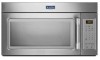
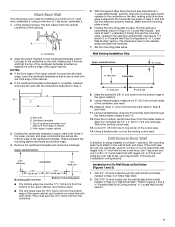
...) min. 14" (35.6 cm) max. A. 2" x 4" wall stud B. The microwave oven is properly grounded. Do not remove ground prong. Exact dimensions may vary depending on type of electric shock. Do not use of electric shock by providing an escape wire for 66" (167.6 cm) installation height...whether the microwave oven is equipped with a cord having a grounding wire with a fuse or circuit breaker. See "Electrical Requirements" section. Product Dimensions 17¹⁄₄" (43.8 cm) 16¹⁄₄" (41.3 cm) (1(+.40/0-1c.³05m⁄₈³c")⁄₄...
...) min. 14" (35.6 cm) max. A. 2" x 4" wall stud B. The microwave oven is properly grounded. Do not remove ground prong. Exact dimensions may vary depending on type of electric shock. Do not use of electric shock by providing an escape wire for 66" (167.6 cm) installation height...whether the microwave oven is equipped with a cord having a grounding wire with a fuse or circuit breaker. See "Electrical Requirements" section. Product Dimensions 17¹⁄₄" (43.8 cm) 16¹⁄₄" (41.3 cm) (1(+.40/0-1c.³05m⁄₈³c")⁄₄...
Installation Guide
Page 7
...) on at least 1 wall stud, the mounting plate must attach to the horizontal line drawn in Step 3, and that its top is level with the dimensions described in Step 4. Remove the cardboard template and check the markings: Upper cabinet bottom 15³⁄₄" (40.0 cm) Centerline 17¹⁄₄...
...) on at least 1 wall stud, the mounting plate must attach to the horizontal line drawn in Step 3, and that its top is level with the dimensions described in Step 4. Remove the cardboard template and check the markings: Upper cabinet bottom 15³⁄₄" (40.0 cm) Centerline 17¹⁄₄...

Installation Guide
Page 8
...." NOTES: ■ If the upper cabinet has a frame around it, trim the template edges so that it is maintained. Make sure the 10" (25.4 cm) dimension from the back of the mounting plate. If installing on a second wall stud, insert a lag screw into the wall stud at both end holes. 3. Start...
...." NOTES: ■ If the upper cabinet has a frame around it, trim the template edges so that it is maintained. Make sure the 10" (25.4 cm) dimension from the back of the mounting plate. If installing on a second wall stud, insert a lag screw into the wall stud at both end holes. 3. Start...
