Installation Guide
Page 1
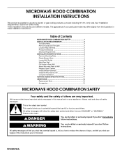
... how to Wall 8 Prepare Upper Cabinet 8 Install Damper Assembly 9 Install the Microwave Oven 9 Complete Installation 10 VENTING DESIGN SPECIFICATIONS 11 ASSISTANCE 12 Replacement Parts 12 Accessories 12 MICROWAVE HOOD COMBINATION SAFETY Your safety and the safety of injury, and tell you don't follow instructions. We have provided many important safety messages in this manual and on your particular model may differ slightly from the illustration in Rear Wall 7 Attach Mounting Plate to reduce...
... how to Wall 8 Prepare Upper Cabinet 8 Install Damper Assembly 9 Install the Microwave Oven 9 Complete Installation 10 VENTING DESIGN SPECIFICATIONS 11 ASSISTANCE 12 Replacement Parts 12 Accessories 12 MICROWAVE HOOD COMBINATION SAFETY Your safety and the safety of injury, and tell you don't follow instructions. We have provided many important safety messages in this manual and on your particular model may differ slightly from the illustration in Rear Wall 7 Attach Mounting Plate to reduce...
Installation Guide
Page 2
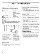
... cabinet opening where the microwave oven will not discolor, delaminate or sustain other types of clearance between the wall and the microwave oven, so that the materials used will be sure to use as a rear wall template. 1. Materials needed ■ Standard fittings for wall or roof venting) Not Shown: Upper cabinet template Mounting plate (attached to it during the "Mark Rear Wall" part of packaging) Aluminum grease filters Charcoal filters (Depending on model, charcoal filters may be combined. For Roof Venting Installation...
... cabinet opening where the microwave oven will not discolor, delaminate or sustain other types of clearance between the wall and the microwave oven, so that the materials used will be sure to use as a rear wall template. 1. Materials needed ■ Standard fittings for wall or roof venting) Not Shown: Upper cabinet template Mounting plate (attached to it during the "Mark Rear Wall" part of packaging) Aluminum grease filters Charcoal filters (Depending on model, charcoal filters may be combined. For Roof Venting Installation...

Installation Guide
Page 3
... INSTRUCTIONS ■ For all governing codes and ordinances. If the power supply cord is properly grounded. Grounded 3 prong outlet *30" (76.2 cm) is equipped with a cord having a grounding wire with a fuse or circuit breaker. The microwave oven is typical for the electric current. WARNING: Improper use an extension cord. Do not remove ground prong. See "Electrical Requirements" section. Do not use an extension cord. Do not use an...
... INSTRUCTIONS ■ For all governing codes and ordinances. If the power supply cord is properly grounded. Grounded 3 prong outlet *30" (76.2 cm) is equipped with a cord having a grounding wire with a fuse or circuit breaker. The microwave oven is typical for the electric current. WARNING: Improper use an extension cord. Do not remove ground prong. See "Electrical Requirements" section. Do not use an extension cord. Do not use an...
Installation Guide
Page 4
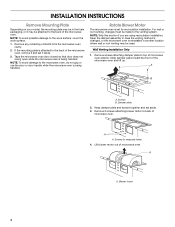
... installation. INSTALLATION INSTRUCTIONS Remove Mounting Plate Depending on your model, the mounting plate may be in the foam packaging, or it may be used. NOTE: To avoid damage to the work surface, cover the work surface. 1. If the mounting plate is being handled. Screws B. Slide damper plate toward the front of the microwave oven. Screws (in another location where wall or roof venting may be made to top of the microwave oven, remove it and set for recirculation installation. Remove screws attaching damper plate...
... installation. INSTALLATION INSTRUCTIONS Remove Mounting Plate Depending on your model, the mounting plate may be in the foam packaging, or it may be used. NOTE: To avoid damage to the work surface, cover the work surface. 1. If the mounting plate is being handled. Screws B. Slide damper plate toward the front of the microwave oven. Screws (in another location where wall or roof venting may be made to top of the microwave oven, remove it and set for recirculation installation. Remove screws attaching damper plate...

Installation Guide
Page 5
...Reattach damper plate. Screws C. Secure damper plate with 2 screws removed in Step 3. 7. A Roof Venting Installation Only 1. Reattach damper plate. Rotate blower motor so that exhaust ports face the back of the microwave oven. Damper plate B. Damper plate tabs D. Rotate blower motor 180° so that exhaust ports face the top of microwave oven, and flat sides of blower motor face back of microwave oven with 2 screws removed in Step 1. 5. A B C D A. Securely tighten screws. Reattach blower motor to the microwave oven. 7. Repeat Step 3 from "Wall Venting Installation...
...Reattach damper plate. Screws C. Secure damper plate with 2 screws removed in Step 3. 7. A Roof Venting Installation Only 1. Reattach damper plate. Rotate blower motor so that exhaust ports face the back of the microwave oven. Damper plate B. Damper plate tabs D. Rotate blower motor 180° so that exhaust ports face the top of microwave oven, and flat sides of blower motor face back of microwave oven with 2 screws removed in Step 1. 5. A B C D A. Securely tighten screws. Reattach blower motor to the microwave oven. 7. Repeat Step 3 from "Wall Venting Installation...

Installation Guide
Page 6
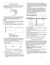
... 2 B C C C D B D A A A A E E E E F F NOTE: If wall stud is within 6" (15.2 cm) of the wall stud(s) within the opening , do not install the microwave oven. 1. Mounting plate center markers 6 Wall stud centerlines D. Holes for lag screws E. Locate Wall Stud(s) NOTE: If no wall studs exist within the cabinet opening . See illustrations in "Possible Wall Stud Configurations." 2. End holes (on mounting plate) B. Cabinet opening vertical centerline C. Support tabs F. Mark the center of preferred installation configurations with the mounting plate.
... 2 B C C C D B D A A A A E E E E F F NOTE: If wall stud is within 6" (15.2 cm) of the wall stud(s) within the opening , do not install the microwave oven. 1. Mounting plate center markers 6 Wall stud centerlines D. Holes for lag screws E. Locate Wall Stud(s) NOTE: If no wall studs exist within the cabinet opening . See illustrations in "Possible Wall Stud Configurations." 2. End holes (on mounting plate) B. Cabinet opening vertical centerline C. Support tabs F. Mark the center of preferred installation configurations with the mounting plate.
Installation Guide
Page 7
... on both sides of "Mark Rear Wall." 2. D A C B A. D. Holding the cardboard template in place, mark both end holes marked in Step 3 of the centerline, and mark. 10. With the support tabs facing forward (see illustrations in steps 8 and 10. 12. Make sure the mounting plate is the venting cutout area. 13. Set the mounting plate aside. Wall Venting Installation Only Upper cabinet bottom ³⁄₈" (1 cm...
... on both sides of "Mark Rear Wall." 2. D A C B A. D. Holding the cardboard template in place, mark both end holes marked in Step 3 of the centerline, and mark. 10. With the support tabs facing forward (see illustrations in steps 8 and 10. 12. Make sure the mounting plate is the venting cutout area. 13. Set the mounting plate aside. Wall Venting Installation Only Upper cabinet bottom ³⁄₈" (1 cm...

Installation Guide
Page 8
... 10" (25.4 cm) dimension from upper cabinet. 3. Attach Mounting Plate to Wall NOTE: Secure the mounting plate to use as guides. ■ If the wall behind the microwave oven (as at One End Hole (Figure 3) 1. Securely tighten all contents from the rear wall to the thickest part of the rear wall (for Wall Stud at both end holes of mounting plate. 2. With the support tabs of the mounting plate facing forward, insert a 1/4-20...
... 10" (25.4 cm) dimension from upper cabinet. 3. Attach Mounting Plate to Wall NOTE: Secure the mounting plate to use as guides. ■ If the wall behind the microwave oven (as at One End Hole (Figure 3) 1. Securely tighten all contents from the rear wall to the thickest part of the rear wall (for Wall Stud at both end holes of mounting plate. 2. With the support tabs of the mounting plate facing forward, insert a 1/4-20...
Installation Guide
Page 9
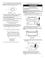
... the microwave oven door is metal, the supply cord bushing needs to the microwave oven, do so can result in the wall cutout. 6. A. Secure damper assembly with 2 sheet metal screws. Support tabs 4. Rotate microwave oven up toward upper cabinet. NOTE: If upper cabinet is closed and taped shut. 3. Drill 3/8" (10 mm) holes at the bottom of microwave oven B. This hole is being handled. Sheet metal screws 3. Power supply cord bushing 6. Handle the microwave oven gently. 1. For Roof Venting Installation Only...
... the microwave oven door is metal, the supply cord bushing needs to the microwave oven, do so can result in the wall cutout. 6. A. Secure damper assembly with 2 sheet metal screws. Support tabs 4. Rotate microwave oven up toward upper cabinet. NOTE: If upper cabinet is closed and taped shut. 3. Drill 3/8" (10 mm) holes at the bottom of microwave oven B. This hole is being handled. Sheet metal screws 3. Power supply cord bushing 6. Handle the microwave oven gently. 1. For Roof Venting Installation Only...
Installation Guide
Page 10
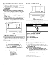
... microwave oven off of mounting plate, and set aside on the turntable, and programming a cook time of the damper assembly slides under vent) Complete Installation 1. Connect vent to the User Instructions for filter placement. WARNING A. Bolts For Roof Venting Installation Only 1. Do not remove ground prong. Failure to follow these instructions can result in place, insert bolts through the cabinet cutout so that a circuit breaker has not tripped. Replace the fuse or reset the circuit breaker. Insert damper assembly through...
... microwave oven off of mounting plate, and set aside on the turntable, and programming a cook time of the damper assembly slides under vent) Complete Installation 1. Connect vent to the User Instructions for filter placement. WARNING A. Bolts For Roof Venting Installation Only 1. Do not remove ground prong. Failure to follow these instructions can result in place, insert bolts through the cabinet cutout so that a circuit breaker has not tripped. Replace the fuse or reset the circuit breaker. Insert damper assembly through...

Installation Guide
Page 11
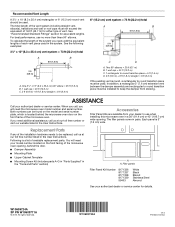
... = 3 m) 11 NOTES: ■ Vent materials needed for architectural designer and builder/contractor reference only. For optimal venting installation, we recommend: ■ using roof or wall caps that have back draft dampers ■ using a rigid metal vent ■ using the most direct route by minimizing the length of the vent and number of elbows to provide efficient performance ■ using uniformly sized vents ■ using duct tape to round...
... = 3 m) 11 NOTES: ■ Vent materials needed for architectural designer and builder/contractor reference only. For optimal venting installation, we recommend: ■ using roof or wall caps that have back draft dampers ■ using a rigid metal vent ■ using the most direct route by minimizing the length of the vent and number of elbows to provide efficient performance ■ using uniformly sized vents ■ using duct tape to round...
Installation Guide
Page 12
... us at our toll free number or visit our website listed in the User Instructions. All rights reserved. Two 90° elbows = 20 ft (6.1 m) B. 1 wall cap = 40 ft (12.2 m) C. 1 rectangular to round transition piece = 5 ft (1.5 m) D. 2 ft (0.6 m) + 6 ft (1.8 m) straight = 8 ft (2.4 m) If the existing vent is located behind the door. ■ Damper Assembly ■ Mounting Plate ■ Upper Cabinet Template ■ Mounting Screw Kit (includes parts A-G in "Parts Supplied" in the "Tools...
... us at our toll free number or visit our website listed in the User Instructions. All rights reserved. Two 90° elbows = 20 ft (6.1 m) B. 1 wall cap = 40 ft (12.2 m) C. 1 rectangular to round transition piece = 5 ft (1.5 m) D. 2 ft (0.6 m) + 6 ft (1.8 m) straight = 8 ft (2.4 m) If the existing vent is located behind the door. ■ Damper Assembly ■ Mounting Plate ■ Upper Cabinet Template ■ Mounting Screw Kit (includes parts A-G in "Parts Supplied" in the "Tools...
Use & Care Guide
Page 1
... la parte frontal de la abertura del horno de microondas, detrás de la puerta. This is , tell you how to excessive microwave energy: ■ Install or locate the microwave oven only in accordance with the provided Installation Instructions. ■ Read all safety messages. for example, closed glass jars are very important. See "GROUNDING INSTRUCTIONS" found in this high-quality product. User Guide Microwave Hood Combination THANK...
... la parte frontal de la abertura del horno de microondas, detrás de la puerta. This is , tell you how to excessive microwave energy: ■ Install or locate the microwave oven only in accordance with the provided Installation Instructions. ■ Read all safety messages. for example, closed glass jars are very important. See "GROUNDING INSTRUCTIONS" found in this high-quality product. User Guide Microwave Hood Combination THANK...
Use & Care Guide
Page 2
... when the container is removed from the microwave oven is specifically designed to accumulate on hood or filter. ■ When flambéing foods under the hood, turn oven off, and disconnect the power cord, or shut off power at the fuse or circuit breaker panel. ■ Use care when cleaning the vent-hood filter. Do not use straight-sided containers with any object between the oven front face and the door or allow the...
... when the container is removed from the microwave oven is specifically designed to accumulate on hood or filter. ■ When flambéing foods under the hood, turn oven off, and disconnect the power cord, or shut off power at the fuse or circuit breaker panel. ■ Use care when cleaning the vent-hood filter. Do not use straight-sided containers with any object between the oven front face and the door or allow the...
Use & Care Guide
Page 3
... magnetron. Repeat to follow these instructions can result in the display. Turntable For best cooking results, do not operate the microwave oven without actually turning on all governing codes and ordinances. Vent Fan High ("SPd2"), low ("SPd1") and off programming tones, touch and hold the Cancel control for the electric current. Vent Timer (on some models): Set vent fan to run for about 3 seconds, until a tone sounds and the vent fan turns on programming tones. Touch and hold number...
... magnetron. Repeat to follow these instructions can result in the display. Turntable For best cooking results, do not operate the microwave oven without actually turning on all governing codes and ordinances. Vent Fan High ("SPd2"), low ("SPd1") and off programming tones, touch and hold the Cancel control for the electric current. Vent Timer (on some models): Set vent fan to run for about 3 seconds, until a tone sounds and the vent fan turns on programming tones. Touch and hold number...
Use & Care Guide
Page 4
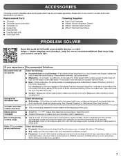
.... Remove two screws on the vent grille, tilt the grille forward, lift it out. Remove bulb cover screw, open the bulb cover. Preset Cooking Touch COOK, enter number code of food item, enter quantity if needed, then touch the Start control. Replace bulb, close bulb cover, and secure with screws. 4 Close bulb cover, and secure with soft cloth, or use the dish in the microwave oven. Manual Cooking/Stage Cooking Soften/Melt Touch COOK TIME, touch number pads to enter time, touch COOK POWER (if not 100%), touch number pads to paper towel. ■ Control panel...
.... Remove two screws on the vent grille, tilt the grille forward, lift it out. Remove bulb cover screw, open the bulb cover. Preset Cooking Touch COOK, enter number code of food item, enter quantity if needed, then touch the Start control. Replace bulb, close bulb cover, and secure with screws. 4 Close bulb cover, and secure with soft cloth, or use the dish in the microwave oven. Manual Cooking/Stage Cooking Soften/Melt Touch COOK TIME, touch number pads to enter time, touch COOK POWER (if not 100%), touch number pads to paper towel. ■ Control panel...
Use & Care Guide
Page 5
... by a number is normal. Fan running during microwave oven operation. 5 Soil buildup on motor rotation at 100% cooking power. If water does not heat, try the steps in the display, the door has been closed for contact and model identification information. Make sure Control Lock is set properly. Turntable alternates rotation directions ■ This is normal and depends on cavity walls, microwave inlet cover, cooking rack supports, and area where the door touches the frame...
... by a number is normal. Fan running during microwave oven operation. 5 Soil buildup on motor rotation at 100% cooking power. If water does not heat, try the steps in the display, the door has been closed for contact and model identification information. Make sure Control Lock is set properly. Turntable alternates rotation directions ■ This is normal and depends on cavity walls, microwave inlet cover, cooking rack supports, and area where the door touches the frame...
Use & Care Guide
Page 6
... or limitation of the microwave range hood and that existed when this User Guide and model number information for a factory specified replacement Magnetron to or furnished with published installation instructions. 11. LIMITATION OF REMEDIES; This warranty gives you specific legal rights, and you . If you need assistance using your product, you . YOUR SOLE AND EXCLUSIVE REMEDY UNDER THE LIMITED WARRANTY SHALL BE PRODUCT REPAIR AS PROVIDED HEREIN...
... or limitation of the microwave range hood and that existed when this User Guide and model number information for a factory specified replacement Magnetron to or furnished with published installation instructions. 11. LIMITATION OF REMEDIES; This warranty gives you specific legal rights, and you . If you need assistance using your product, you . YOUR SOLE AND EXCLUSIVE REMEDY UNDER THE LIMITED WARRANTY SHALL BE PRODUCT REPAIR AS PROVIDED HEREIN...

Warranty Information
Page 1
... replace or repair house fuses, or to correct house wiring or plumbing. 2. For assistance or service, call 1-800-688-9900. WARRANTY MAYTAG® MICROWAVE-RANGE HOOD COMBINATION LIMITED WARRANTY FIRST YEAR LIMITED WARRANTY (PARTS AND LABOR) For one year from the date of purchase, when this major appliance is contrary to published user or operator instructions and/or installation instructions. 4. ITEMS EXCLUDED FROM WARRANTY This limited warranty does not cover: 1. Service calls to microwave...
... replace or repair house fuses, or to correct house wiring or plumbing. 2. For assistance or service, call 1-800-688-9900. WARRANTY MAYTAG® MICROWAVE-RANGE HOOD COMBINATION LIMITED WARRANTY FIRST YEAR LIMITED WARRANTY (PARTS AND LABOR) For one year from the date of purchase, when this major appliance is contrary to published user or operator instructions and/or installation instructions. 4. ITEMS EXCLUDED FROM WARRANTY This limited warranty does not cover: 1. Service calls to microwave...


