
W10240504
Page 1
...electronic, and mechanical experience and knowledge at a level generally considered acceptable in the appliance. Avoid touching electronic parts or terminal contacts; IMPORTANT: Electrostatic Discharge (ESD) Sensitive Electronics ESD problems are in the off position so that the ... of this data sheet. IMPORTANT SAFETY NOTICE - Any attempt to ESD stress. Use an anti-static wrist strap. Contents Whirlpool, Maytag, and Kenmore Control Panels.... 2-4 Diagnostic Guide 5 Activating the Service Diagnostic Mode 5 Key Activation & Encoder Test 6 Service Test Mode 6...
...electronic, and mechanical experience and knowledge at a level generally considered acceptable in the appliance. Avoid touching electronic parts or terminal contacts; IMPORTANT: Electrostatic Discharge (ESD) Sensitive Electronics ESD problems are in the off position so that the ... of this data sheet. IMPORTANT SAFETY NOTICE - Any attempt to ESD stress. Use an anti-static wrist strap. Contents Whirlpool, Maytag, and Kenmore Control Panels.... 2-4 Diagnostic Guide 5 Activating the Service Diagnostic Mode 5 Key Activation & Encoder Test 6 Service Test Mode 6...
W10240504
Page 10
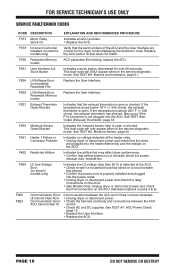
... appear when in the service diagnostic mode. UI Cannot Hear ACU • Unplug dryer or disconnect power. Replace the ACU and/or UI that the part numbers of the ACU and the User Interface are correct for over 20 seconds). F1E5 Parameter Memory Invalid ACU parameter file missing; If the temperature...
... appear when in the service diagnostic mode. UI Cannot Hear ACU • Unplug dryer or disconnect power. Replace the ACU and/or UI that the part numbers of the ACU and the User Interface are correct for over 20 seconds). F1E5 Parameter Memory Invalid ACU parameter file missing; If the temperature...
W10240504
Page 13
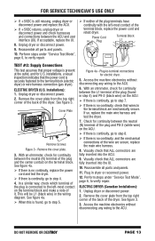
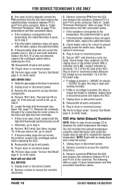
... NOT REMOVE OR DESTROY PAGE 13 FOR SERVICE TECHNICIAN'S USE ONLY If +5VDC is no continuity, check that wires to the ACU. Reassemble all parts and panels. 11. Power Cord N Plug Terminal Block L1 TEST #2: Supply Connections This test assumes that proper voltage is present at the outlet, and for... dryer or disconnect power. 2. Access the machine electronics without disconnecting any wiring to the terminal block are secure, replace the main wire harness. 8. Reassemble all parts and panels. 10.
... NOT REMOVE OR DESTROY PAGE 13 FOR SERVICE TECHNICIAN'S USE ONLY If +5VDC is no continuity, check that wires to the ACU. Reassemble all parts and panels. 11. Power Cord N Plug Terminal Block L1 TEST #2: Supply Connections This test assumes that proper voltage is present at the outlet, and for... dryer or disconnect power. 2. Access the machine electronics without disconnecting any wiring to the terminal block are secure, replace the main wire harness. 8. Reassemble all parts and panels. 10.
W10240504
Page 14
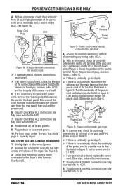
... the position of the power cord itself. 5. harness to the ACU. 5. See figure 3. 3. See figure 5. 4. FOR SERVICE TECHNICIAN'S USE ONLY 4. See figure 4b. Reassemble all parts and panels. 9. Access the machine electronics without disconnecting any wiring to the ACU; N Neu L1 COM L1 G Masse Power Cord Plug N Neu G Masse Figure 6 - Perform...
... the position of the power cord itself. 5. harness to the ACU. 5. See figure 3. 3. See figure 5. 4. FOR SERVICE TECHNICIAN'S USE ONLY 4. See figure 4b. Reassemble all parts and panels. 9. Access the machine electronics without disconnecting any wiring to the ACU; N Neu L1 COM L1 G Masse Power Cord Plug N Neu G Masse Figure 6 - Perform...
W10240504
Page 15
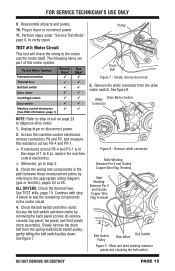
... machine control electronics. Otherwise, go to step 3. 3. See TEST #4b, page 19. Slowly remove the drum belt from the drive motor switch. Reassemble all parts and panels. 10. Pulley TEST #3: Motor Circuit This test will check the wiring to verify repair. Slowly remove drum belt. 5. See figure 7. Remove white connector...
... machine control electronics. Otherwise, go to step 3. 3. See TEST #4b, page 19. Slowly remove the drum belt from the drive motor switch. Reassemble all parts and panels. 10. Pulley TEST #3: Motor Circuit This test will check the wiring to verify repair. Slowly remove drum belt. 5. See figure 7. Remove white connector...
W10240504
Page 16
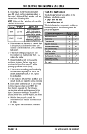
... switch pulley. If the resistance reading goes from infinity to the dryer. TEST #4: Heat System This test is OK. The following items are part of this system: Part of the following table. FOR SERVICE TECHNICIAN'S USE ONLY 6. NOTE: Main and Start winding coils must be done without applying power to a few...
... switch pulley. If the resistance reading goes from infinity to the dryer. TEST #4: Heat System This test is OK. The following items are part of this system: Part of the following table. FOR SERVICE TECHNICIAN'S USE ONLY 6. NOTE: Main and Start winding coils must be done without applying power to a few...
W10240504
Page 18
... K2 heater relay. If voltage is present (~240VAC for electric, ~120VAC for temperatures and their associated resistance values. Reassemble all parts and panels. 9. PAGE 18 DO NOT REMOVE OR DESTROY Measure the continuity through it by connecting the meter probes to the temperature, the...Exhaust) Thermistor NOTE: Refer to "Outlet Thermistor Resistance" table on and off : ALL DRYERS: 1. Remove console to verify repair. Reassemble all parts and panels. 11. Plug in dryer or reconnect power. 12. Refer to strip circuit on page 19 for gas), the relay is open ...
... K2 heater relay. If voltage is present (~240VAC for electric, ~120VAC for temperatures and their associated resistance values. Reassemble all parts and panels. 9. PAGE 18 DO NOT REMOVE OR DESTROY Measure the continuity through it by connecting the meter probes to the temperature, the...Exhaust) Thermistor NOTE: Refer to "Outlet Thermistor Resistance" table on and off : ALL DRYERS: 1. Remove console to verify repair. Reassemble all parts and panels. 11. Plug in dryer or reconnect power. 12. Refer to strip circuit on page 19 for gas), the relay is open ...
W10240504
Page 20
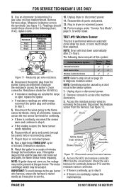
... come out and ignite, the flame sensor needs replacing. Readings should be present at least 2 minutes in the sensor system. 1. Reassemble all parts and panels. 12. if not, replace coils. 10. If the ignitor stays red hot and the gas does not come on page 23 ...IMPORTANT: To avoid damage to the gas burner wire harness, ensure the harness is open , replace the ignitor. If resistance readings are part of at the gas burner. Drum FRONT MOVs (Metal Oxide Varistors) Blower Housing Harness Connection Figure 12 - Remove harness plugs. Watch the ignitor for...
... come out and ignite, the flame sensor needs replacing. Readings should be present at least 2 minutes in the sensor system. 1. Reassemble all parts and panels. 12. if not, replace coils. 10. If the ignitor stays red hot and the gas does not come on page 23 ...IMPORTANT: To avoid damage to the gas burner wire harness, ensure the harness is open , replace the ignitor. If resistance readings are part of at the gas burner. Drum FRONT MOVs (Metal Oxide Varistors) Blower Housing Harness Connection Figure 12 - Remove harness plugs. Watch the ignitor for...
W10240504
Page 21
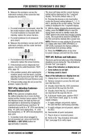
... time to verify supply voltages. If supply voltages are present, replace the user interface and housing assembly. If supply voltages are inserted all parts and panels. 7. If all the way into the ACU. 4. Plug in the 7-segment display. 3. Perform the "Key Activation & Encoder Test" (see page 6). 3 None of the...
... time to verify supply voltages. If supply voltages are present, replace the user interface and housing assembly. If supply voltages are inserted all parts and panels. 7. If all the way into the ACU. 4. Plug in the 7-segment display. 3. Perform the "Key Activation & Encoder Test" (see page 6). 3 None of the...

W10240504
Page 22
... replace the ACU. 4. Press the SIGNAL, AUDIO LEVEL, or CYCLE SIGNAL button to P9-2 (L1) (see figure 2, page 12). Reassemble all parts and panels. Unplug dryer or disconnect power. 2. Make sure that ALL ACU connectors are connected. (Refer to verify repair. Plug in dryer or reconnect...adjust the volume level. 2. Remove console to access the ACU and user interface (UI). 4. PAGE 22 DO NOT REMOVE OR DESTROY Reassemble all parts and panels. 8. Verify that it stops when the door opens. Remove console to access the machine electronics. 3. TEST #8: Drum Light This test...
... replace the ACU. 4. Press the SIGNAL, AUDIO LEVEL, or CYCLE SIGNAL button to P9-2 (L1) (see figure 2, page 12). Reassemble all parts and panels. Unplug dryer or disconnect power. 2. Make sure that ALL ACU connectors are connected. (Refer to verify repair. Plug in dryer or reconnect...adjust the volume level. 2. Remove console to access the ACU and user interface (UI). 4. PAGE 22 DO NOT REMOVE OR DESTROY Reassemble all parts and panels. 8. Verify that it stops when the door opens. Remove console to access the machine electronics. 3. TEST #8: Drum Light This test...


