W10240504
Page 1
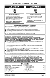
... metal in personal injury and property damage. Contents Whirlpool, Maytag, and Kenmore Control Panels.... 2-4 Diagnostic Guide 5 Activating the Service Diagnostic Mode 5 Key Activation & Encoder Test 6 Service Test Mode 6 Service Test Mode Chart 7, 8 Software Version Display 9 Fault/Error Codes 9, 10 Troubleshooting Guide 11 Troubleshooting Tests 12-22 Strip Circuits 23 Wiring Diagrams 24, 25 Component Locations 26 DPAORNTONTOR. EWM1O0V91E3O9R69DAESTROY PAGE 1 FOR SERVICE TECHNICIAN'S USE ONLY Voltage Measurement Safety Information When performing live voltage...
... metal in personal injury and property damage. Contents Whirlpool, Maytag, and Kenmore Control Panels.... 2-4 Diagnostic Guide 5 Activating the Service Diagnostic Mode 5 Key Activation & Encoder Test 6 Service Test Mode 6 Service Test Mode Chart 7, 8 Software Version Display 9 Fault/Error Codes 9, 10 Troubleshooting Guide 11 Troubleshooting Tests 12-22 Strip Circuits 23 Wiring Diagrams 24, 25 Component Locations 26 DPAORNTONTOR. EWM1O0V91E3O9R69DAESTROY PAGE 1 FOR SERVICE TECHNICIAN'S USE ONLY Voltage Measurement Safety Information When performing live voltage...

W10240504
Page 5
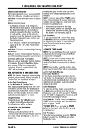
... wires and terminals, pin insertion, or wires not pressed into connectors far enough to test and verify all of step 3 is required. Is dryer vent properly installed and clear of lint or obstructions? All tests/checks should be made with these buttons. Look for 5 secs. - ACTIVATING SERVICE DIAGNOSTIC MODE 1. SERVICE DIAGNOSTIC MENU TABLE Button Press Function Behavior 1st Button 2nd Button 3rd Button - Momentary press - Clears the Error Codes...
... wires and terminals, pin insertion, or wires not pressed into connectors far enough to test and verify all of step 3 is required. Is dryer vent properly installed and clear of lint or obstructions? All tests/checks should be made with these buttons. Look for 5 secs. - ACTIVATING SERVICE DIAGNOSTIC MODE 1. SERVICE DIAGNOSTIC MENU TABLE Button Press Function Behavior 1st Button 2nd Button 3rd Button - Momentary press - Clears the Error Codes...
W10240504
Page 6
... selecting the cycle, go to activate Service Diagnostic mode. Action: Select any point, the user presses the POWER button or opens the door during Service Test Mode, the dryer exits to run only the voltage test. see procedure on after step 3 to standby mode. PERFORM ALL TESTS: Press and release the START button to run correctly. VOLTAGE TEST: Press and hold the first button used to TEST #1, ACU Power Check, page 12...
... selecting the cycle, go to activate Service Diagnostic mode. Action: Select any point, the user presses the POWER button or opens the door during Service Test Mode, the dryer exits to run only the voltage test. see procedure on after step 3 to standby mode. PERFORM ALL TESTS: Press and release the START button to run correctly. VOLTAGE TEST: Press and hold the first button used to TEST #1, ACU Power Check, page 12...

W10240504
Page 7
... SERVICE TECHNICIAN'S USE ONLY SERVICE TEST MODE CHART Step # Action Component User Interface Response 1 User enters Service Test Mode through Service Diagnostics. Display shows "888" for POWER) are off, and the START button is available, a tone will continue to display as in Step 4. L1 Voltage Check starts automatically. If START is pressed again or pressed and held before L1 voltage is flashing. 2 Press and release START Motor On...
... SERVICE TECHNICIAN'S USE ONLY SERVICE TEST MODE CHART Step # Action Component User Interface Response 1 User enters Service Test Mode through Service Diagnostics. Display shows "888" for POWER) are off, and the START button is available, a tone will continue to display as in Step 4. L1 Voltage Check starts automatically. If START is pressed again or pressed and held before L1 voltage is flashing. 2 Press and release START Motor On...
W10240504
Page 8
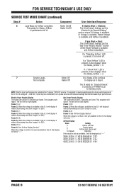
... will be right aligned. Frame 3: Air Frame 4: See "Airflow Display Section". Airflow Display Value 0 1 2 3 (Default) Setting Airflow not bad Cannot detect Airflow bad; Status_Airflow = 0 will display it also displays when the Status_Airflow = 2. 7 Service Loads Motor Off Test complete. If a "Check Vent" LED is available to 200). FOR SERVICE TECHNICIAN'S USE ONLY SERVICE TEST MODE CHART (continued) Step # Action Component User Interface Response 6 Load Mass for...
... will be right aligned. Frame 3: Air Frame 4: See "Airflow Display Section". Airflow Display Value 0 1 2 3 (Default) Setting Airflow not bad Cannot detect Airflow bad; Status_Airflow = 0 will display it also displays when the Status_Airflow = 2. 7 Service Loads Motor Off Test complete. If a "Check Vent" LED is available to 200). FOR SERVICE TECHNICIAN'S USE ONLY SERVICE TEST MODE CHART (continued) Step # Action Component User Interface Response 6 Load Mass for...

W10240504
Page 9
... 3rd button will time out after 10 minutes of user inactivity and return to enter Service Diagnostic mode for 5 seconds. Confirm that a power failure occurred while the dryer was running. Clearing Fault Codes To clear stored fault codes, enter Service Diagnostic mode. EXITING SERVICE DIAGNOSTIC MODE Use either of the two methods below and service fault/error codes on diagnostic procedure. Press START to continue the cycle...
... 3rd button will time out after 10 minutes of user inactivity and return to enter Service Diagnostic mode for 5 seconds. Confirm that a power failure occurred while the dryer was running. Clearing Fault Codes To clear stored fault codes, enter Service Diagnostic mode. EXITING SERVICE DIAGNOSTIC MODE Use either of the two methods below and service fault/error codes on diagnostic procedure. Press START to continue the cycle...
W10240504
Page 10
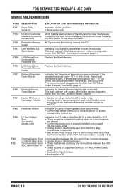
... temperature is open or shorted. F2E1 User Interface (UI) Stuck Button Indicates a stuck button (depressed for the dryer model displaying the fault/error code. Replace the ACU and/or UI that the wires are correct for over 20 seconds). F4E1 Heater 1 Failure or Indicates no voltage detected at the ACU. check lint screen, exhaust duct, exhaust fan. F3E1 Exhaust Thermistor Open/Shorted Indicates that the exhaust thermistor is not plugged into the power outlet. • Unplug dryer...
... temperature is open or shorted. F2E1 User Interface (UI) Stuck Button Indicates a stuck button (depressed for the dryer model displaying the fault/error code. Replace the ACU and/or UI that the wires are correct for over 20 seconds). F4E1 Heater 1 Failure or Indicates no voltage detected at the ACU. check lint screen, exhaust duct, exhaust fan. F3E1 Exhaust Thermistor Open/Shorted Indicates that the exhaust thermistor is not plugged into the power outlet. • Unplug dryer...
W10240504
Page 11
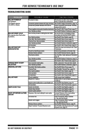
... Dryness Level, page 21. See Test #2: Supply Connections, page 13. Connection problem between ACU and UI. User Interface problem. Check lint screen and exhaust vent. ACU problem. Check connections and harness continuity between ACU and UI. See Test #7: Door Switch, page 22. Check the Start/Pause button. User Interface problem. ACU problem. Verify proper dryer installation. Refer customer to "Use and Care Guide". No operation - Clean if necessary. Refer customer to dryer. See Test #3: Motor Circuit, page 15. Adjust Customer Focused...
... Dryness Level, page 21. See Test #2: Supply Connections, page 13. Connection problem between ACU and UI. User Interface problem. Check lint screen and exhaust vent. ACU problem. Check connections and harness continuity between ACU and UI. See Test #7: Door Switch, page 22. Check the Start/Pause button. User Interface problem. ACU problem. Verify proper dryer installation. Refer customer to "Use and Care Guide". No operation - Clean if necessary. Refer customer to dryer. See Test #3: Motor Circuit, page 15. Adjust Customer Focused...

W10240504
Page 12
... fuse. If CB (circuit breaker) is present at the machine control electronics. Unplug dryer or disconnect power. Perform voltage check inside header P2 on ACU, between pins 1 & 3-DO NOT SHORT PINS TOGETHER. TEST #1: ACU Power Check This test is used to P2-1 (+5V DC). Remove console to step 8. If +5VDC is not present, check for appropriate line voltages at the outlet. 1. With voltmeter set to AC, connect...
... fuse. If CB (circuit breaker) is present at the machine control electronics. Unplug dryer or disconnect power. Perform voltage check inside header P2 on ACU, between pins 1 & 3-DO NOT SHORT PINS TOGETHER. TEST #1: ACU Power Check This test is used to P2-1 (+5V DC). Remove console to step 8. If +5VDC is not present, check for appropriate line voltages at the outlet. 1. With voltmeter set to AC, connect...
W10240504
Page 13
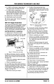
... continuity, replace the power cord and test the dryer. If there is securely fastened to step 4. 4. With an ohmmeter, check for continuity between the ACU and user interface (UI). FOR SERVICE TECHNICIAN'S USE ONLY If +5VDC is present at the outlet, and for U.S. Power Cord N Plug Terminal Block L1 TEST #2: Supply Connections This test assumes that ALL connectors are secure, replace the main wire harness. 8. See figure 3. Remove the cover plate...
... continuity, replace the power cord and test the dryer. If there is securely fastened to step 4. 4. With an ohmmeter, check for continuity between the ACU and user interface (UI). FOR SERVICE TECHNICIAN'S USE ONLY If +5VDC is present at the outlet, and for U.S. Power Cord N Plug Terminal Block L1 TEST #2: Supply Connections This test assumes that ALL connectors are secure, replace the main wire harness. 8. See figure 3. Remove the cover plate...
W10240504
Page 14
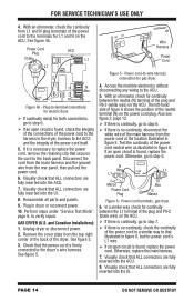
.... Test the continuity of the power cord in the dryer; Visually check that illustrated in figure 5. With an ohmmeter, check for power cord's L1 wire. If an open circuit is no continuity, disconnect the white wire of the main harness from L1 and N plug terminals of the power cord itself. 5. If it is firmly connected to that ALL connectors are fully inserted into the UI. FOR SERVICE TECHNICIAN'S USE...
.... Test the continuity of the power cord in the dryer; Visually check that illustrated in figure 5. With an ohmmeter, check for power cord's L1 wire. If an open circuit is no continuity, disconnect the white wire of the main harness from L1 and N plug terminals of the power cord itself. 5. If it is firmly connected to that ALL connectors are fully inserted into the UI. FOR SERVICE TECHNICIAN'S USE...
W10240504
Page 15
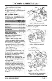
... drive motor. 1. White Drive Motor Switch Connector 264 3 5 1 NOTE: Refer to strip circuit on page 23 to the motor and the motor itself. Check the belt switch and drive motor. Slowly remove the drum belt from the drive motor switch. Figure 8 - FOR SERVICE TECHNICIAN'S USE ONLY 9. Reassemble all parts and panels. 10. Slowly remove drum belt. 5. See figure 8. Check the wiring and components in dryer or reconnect power. 11. ALL DRYERS: Check the thermal fuse. See TEST #4b, page 19. Main and start...
... drive motor. 1. White Drive Motor Switch Connector 264 3 5 1 NOTE: Refer to strip circuit on page 23 to the motor and the motor itself. Check the belt switch and drive motor. Slowly remove the drum belt from the drive motor switch. Figure 8 - FOR SERVICE TECHNICIAN'S USE ONLY 9. Reassemble all parts and panels. 10. Slowly remove drum belt. 5. See figure 8. Check the wiring and components in dryer or reconnect power. 11. ALL DRYERS: Check the thermal fuse. See TEST #4b, page 19. Main and start...
W10240504
Page 16
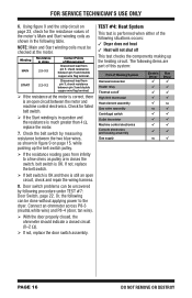
... not, replace the door switch assembly. Check the belt switch by following table. Or, the following can be done without applying power to a few ohms as shown in ohms MAIN 2.5-3.5 START 2.2-3.2 Contact Points of Heating System Harness/connection Heater relay Thermal cut-off This test checks the components making up the belt switch pulley. If the resistance reading goes from infinity to the dryer. FOR SERVICE TECHNICIAN'S USE ONLY...
... not, replace the door switch assembly. Check the belt switch by following table. Or, the following can be done without applying power to a few ohms as shown in ohms MAIN 2.5-3.5 START 2.2-3.2 Contact Points of Heating System Harness/connection Heater relay Thermal cut-off This test checks the components making up the belt switch pulley. If the resistance reading goes from infinity to the dryer. FOR SERVICE TECHNICIAN'S USE ONLY...
W10240504
Page 17
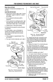
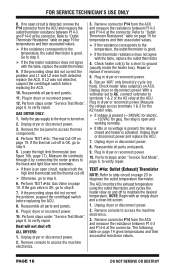
... wire). Visually check the wire connections at the thermal cut-off if it is electrically open circuit is detected, go to the wiring diagram, measure continuity from front. Check Thermal Cut-off-using figures 10a and 10b. Check High Limit Thermostat-visually check the wire connections from front. 4. DO NOT REMOVE OR DESTROY PAGE 17 High Limit Thermostat Thermal Cut-Off Flame Sensor Thermal Fuse Outlet Thermistor Gas Dryer Figure 10b - Remove the toe panel to the red wire terminal...
... wire). Visually check the wire connections at the thermal cut-off if it is electrically open circuit is detected, go to the wiring diagram, measure continuity from front. Check Thermal Cut-off-using figures 10a and 10b. Check High Limit Thermostat-visually check the wire connections from front. 4. DO NOT REMOVE OR DESTROY PAGE 17 High Limit Thermostat Thermal Cut-Off Flame Sensor Thermal Fuse Outlet Thermistor Gas Dryer Figure 10b - Remove the toe panel to the red wire terminal...
W10240504
Page 18
... 10b, page 17). With a voltmeter set to AC, connect voltmeter to verify repair. NOTE: Begin with the table, replace the outlet thermistor. 4. Unplug dryer or disconnect power. 2. Remove console to access the machine electronics. 3. Repair or replace if necessary. 5. GAS DRYER ONLY: 1. Heat will not shut off . Otherwise, go to verify repair. The following table on page 19. If no open and working normally. If little or...
... 10b, page 17). With a voltmeter set to AC, connect voltmeter to verify repair. NOTE: Begin with the table, replace the outlet thermistor. 4. Unplug dryer or disconnect power. 2. Remove console to access the machine electronics. 3. Repair or replace if necessary. 5. GAS DRYER ONLY: 1. Heat will not shut off . Otherwise, go to verify repair. The following table on page 19. If no open and working normally. If little or...
W10240504
Page 19
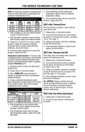
... at least 2 minutes in series with temperature setting, replace the outlet thermistor. If the temperature probe confirms the temperature setting, retest at any or all of the exhaust outlet. In addition, check for blocked or improper exhaust system, and, on electric dryers, for location. 4. Access the gas valve by removing the toe panel. FOR SERVICE TECHNICIAN'S USE ONLY NOTE: All thermistor resistance measurements must be made while dryer is unplugged and connector removed from dryer and disconnect external vent. 2.
... at least 2 minutes in series with temperature setting, replace the outlet thermistor. If the temperature probe confirms the temperature setting, retest at any or all of the exhaust outlet. In addition, check for blocked or improper exhaust system, and, on electric dryers, for location. 4. Access the gas valve by removing the toe panel. FOR SERVICE TECHNICIAN'S USE ONLY NOTE: All thermistor resistance measurements must be made while dryer is unplugged and connector removed from dryer and disconnect external vent. 2.
W10240504
Page 20
.../connection Electric Gas Dryer Dryer Metal sensor strips Machine control electronics NOTE: Refer to 5 Resistance in the sensor system. 1. Readings should be present at least 2 minutes in the following items are outside the range or open , the flame sensor needs replacing. 6. Measuring gas valve resistance. 4. PAGE 20 DO NOT REMOVE OR DESTROY Reassemble all parts and panels. 12. Run a high-temp TIMED DRY cycle of this system: Black Light Blue White White Light...
.../connection Electric Gas Dryer Dryer Metal sensor strips Machine control electronics NOTE: Refer to 5 Resistance in the sensor system. 1. Readings should be present at least 2 minutes in the following items are outside the range or open , the flame sensor needs replacing. 6. Measuring gas valve resistance. 4. PAGE 20 DO NOT REMOVE OR DESTROY Reassemble all parts and panels. 12. Run a high-temp TIMED DRY cycle of this system: Black Light Blue White White Light...
W10240504
Page 21
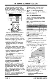
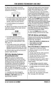
... not light 3 No beep sound is displayed in but not powered up), press and hold the DRYNESS or DRY LEVEL button for 20 seconds, or a button other than infinity is measured, replace the sensor harness. 7. TEST #5a: Adjusting CustomerFocused Dryness Level NOTE: If the customer complains about the clothes being less dry or more drying time), "1" (15% less drying time), or "0" (30% less drying time) auto cycle. 1. Plug in dryer...
... not light 3 No beep sound is displayed in but not powered up), press and hold the DRYNESS or DRY LEVEL button for 20 seconds, or a button other than infinity is measured, replace the sensor harness. 7. TEST #5a: Adjusting CustomerFocused Dryness Level NOTE: If the customer complains about the clothes being less dry or more drying time), "1" (15% less drying time), or "0" (30% less drying time) auto cycle. 1. Plug in dryer...

W10240504
Page 22
... connections are not met: 1. PAGE 22 DO NOT REMOVE OR DESTROY Plug in dryer or reconnect power and press the POWER button. If voltage is present but the drum light does not turn off the drum light. Visually check that the "Signal", "Audio Level", or "Cycle Signal" volume is verified when opening the door turns on . Plug in dryer or reconnect power. 6. TEST #8: Drum Light This test is still not present, replace the ACU. 6. TEST #7: Door Switch...
... connections are not met: 1. PAGE 22 DO NOT REMOVE OR DESTROY Plug in dryer or reconnect power and press the POWER button. If voltage is present but the drum light does not turn off the drum light. Visually check that the "Signal", "Audio Level", or "Cycle Signal" volume is verified when opening the door turns on . Plug in dryer or reconnect power. 6. TEST #8: Drum Light This test is still not present, replace the ACU. 6. TEST #7: Door Switch...
W10240504
Page 26
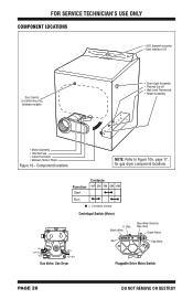
... 17, for gas dryer component locations. Contacts Function 1M 2M 3M 5M 6M Start Run = Contacts closed Centrifugal Switch (Motor) Black Light Blue White White Light Blue Gas Valve, Gas Dryer Lt. FOR SERVICE TECHNICIAN'S USE ONLY COMPONENT LOCATIONS • ACU (beneath console) • User Interface (UI) Door Switch (Location may vary between models) • Drum Light Assembly • Thermal Cut-off • High Limit Thermostat • Heater Assembly • Motor Assembly • Thermal Fuse • Outlet Thermistor • Moisture Sensor Strips Figure 16...
... 17, for gas dryer component locations. Contacts Function 1M 2M 3M 5M 6M Start Run = Contacts closed Centrifugal Switch (Motor) Black Light Blue White White Light Blue Gas Valve, Gas Dryer Lt. FOR SERVICE TECHNICIAN'S USE ONLY COMPONENT LOCATIONS • ACU (beneath console) • User Interface (UI) Door Switch (Location may vary between models) • Drum Light Assembly • Thermal Cut-off • High Limit Thermostat • Heater Assembly • Motor Assembly • Thermal Fuse • Outlet Thermistor • Moisture Sensor Strips Figure 16...


