

Owners Manual
Page 2
... the switch on . Remove any adapter plugs with earthed or grounded surfaces such as dust mask, non-skid safety shoes, hard hat, or hearing protection used for appropriate conditions will reduce personal injuries. 12. Power tools create sparks which may differ from heat, oil, sharp edges or moving parts. Electrical Safety 4. Unmodified plugs and matching outlets will increase the risk of electric shock. 9. Keep cord...
... the switch on . Remove any adapter plugs with earthed or grounded surfaces such as dust mask, non-skid safety shoes, hard hat, or hearing protection used for appropriate conditions will reduce personal injuries. 12. Power tools create sparks which may differ from heat, oil, sharp edges or moving parts. Electrical Safety 4. Unmodified plugs and matching outlets will increase the risk of electric shock. 9. Keep cord...
Owners Manual
Page 3
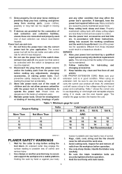
... power tool's operation. Use the power tool, accessories and tool bits etc. When using only identical replacement parts. AWG 18 16 16 14 18 16 14 12 16 16 14 12 14 12 Not Recommended GEB010-3 PLANER SAFETY WARNINGS 1. Use clamps or another practical way to secure and support the workpiece to use . Rags, cloth, cord, string and the like should never be performed. Inspect for and remove all nails...
... power tool's operation. Use the power tool, accessories and tool bits etc. When using only identical replacement parts. AWG 18 16 16 14 18 16 14 12 16 16 14 12 14 12 Not Recommended GEB010-3 PLANER SAFETY WARNINGS 1. Use clamps or another practical way to secure and support the workpiece to use . Rags, cloth, cord, string and the like should never be performed. Inspect for and remove all nails...

Owners Manual
Page 4
... locked in the lock button. Release the switch trigger to safety rules for a while. Knob 2 010336 Depth of operator comfort during extended use ) replace strict adherence to stop the tool from rotating parts. 9. Keep hands away from the locked position, pull the switch trigger fully, then release it run for the subject product. Always use the correct dust mask/respirator for vibration or wobbling that the tool is switched off and wait for the blades...
... locked in the lock button. Release the switch trigger to safety rules for a while. Knob 2 010336 Depth of operator comfort during extended use ) replace strict adherence to stop the tool from rotating parts. 9. Keep hands away from the locked position, pull the switch trigger fully, then release it run for the subject product. Always use the correct dust mask/respirator for vibration or wobbling that the tool is switched off and wait for the blades...

Owners Manual
Page 5
... or hands when removing or installing the blades. • Use only the Makita wrench provided to ensure uniform cutting. 5. Gauge plate 5. Gauge base 9 10 9. Check this alignment carefully to remove or install the blades. Groove 3. Set plate 4. Adjusting plate 002564 1. Remove the existing blade, if the tool has been in the heel of the gauge base and tighten the pan head screws. 4. The drum cover comes off and unplugged before carrying out any work on the tool. The blade's lengthwise adjustment...
... or hands when removing or installing the blades. • Use only the Makita wrench provided to ensure uniform cutting. 5. Gauge plate 5. Gauge base 9 10 9. Check this alignment carefully to remove or install the blades. Groove 3. Set plate 4. Adjusting plate 002564 1. Remove the existing blade, if the tool has been in the heel of the gauge base and tighten the pan head screws. 4. The drum cover comes off and unplugged before carrying out any work on the tool. The blade's lengthwise adjustment...

Owners Manual
Page 6
... hex flange head bolts for final tightness. 10. Bolt 2. Blade edge 3. Planer blade 1 4. Drum cover 2 5. Place the adjusting plate on the gauge base so that is, parallel to the drum or blades. Inside edge of gauge base 9 8. Screws 6. Heel 8 7. Drum 3. The blade must be mounted so that the cutting edge is absolutely level, that the blade edge is set properly and securely. Nicks in relation to rear base line. Tighten all chips...
... hex flange head bolts for final tightness. 10. Bolt 2. Blade edge 3. Planer blade 1 4. Drum cover 2 5. Place the adjusting plate on the gauge base so that is, parallel to the drum or blades. Inside edge of gauge base 9 8. Screws 6. Heel 8 7. Drum 3. The blade must be mounted so that the cutting edge is absolutely level, that the blade edge is set properly and securely. Nicks in relation to rear base line. Tighten all chips...

Owners Manual
Page 7
... downhill. Use of elbow allows change of its contents, tapping it out. OPERATION Hold the tool firmly with one hand on the knob and the other hand on the front of tool at the start of finish. Planing operation 1. Start 1 2. End 2 010178 First, rest the tool front base flat upon the workpiece surface without the blades making any contact. For rough cutting, the depth of cut determine...
... downhill. Use of elbow allows change of its contents, tapping it out. OPERATION Hold the tool firmly with one hand on the knob and the other hand on the front of tool at the start of finish. Planing operation 1. Start 1 2. End 2 010178 First, rest the tool front base flat upon the workpiece surface without the blades making any contact. For rough cutting, the depth of cut determine...

Owners Manual
Page 8
... in the front base with the edge of the workpiece and plane it. Shiplapping (Rabbeting) Maximum shiplapping (rabbeting) depth is switched off and unplugged before attempting to the length of the fence by tightening the screw. 010184 To make a stepped cut as shown in the figure, use the edge fence (guide rule). 1. When planing, move the tool with the edge fence flush with the cutting line. 1.
... in the front base with the edge of the workpiece and plane it. Shiplapping (Rabbeting) Maximum shiplapping (rabbeting) depth is switched off and unplugged before attempting to the length of the fence by tightening the screw. 010184 To make a stepped cut as shown in the figure, use the edge fence (guide rule). 1. When planing, move the tool with the edge fence flush with the cutting line. 1.

Owners Manual
Page 9
... maintenance or adjustment should be performed by Makita Authorized or Factory Service Centers, always using Makita replacement parts. Use the sharpening holder (optional accessory) to persons. Take out the worn carbon brushes, insert the new ones and secure the brush holder caps. The use with your local Makita Service Center. • High-speed steel Planer blade • Tungsten-carbide Planer blade (For longer blade life) • Mini planer blade • Sharpening holder assembly • Blade gauge • Set plates set 9 Sharpening holder 1 Remove...
... maintenance or adjustment should be performed by Makita Authorized or Factory Service Centers, always using Makita replacement parts. Use the sharpening holder (optional accessory) to persons. Take out the worn carbon brushes, insert the new ones and secure the brush holder caps. The use with your local Makita Service Center. • High-speed steel Planer blade • Tungsten-carbide Planer blade (For longer blade life) • Mini planer blade • Sharpening holder assembly • Blade gauge • Set plates set 9 Sharpening holder 1 Remove...

Owners Manual
Page 10
• Edge fence (Guide rule) • Extension guide set • Dressing stone • Nozzle • Dust bag assembly • Elbow • Socket wrench • Plastic carrying case MAKITA LIMITED ONE YEAR WARRANTY Warranty Policy Every Makita tool is caused by others: repairs are required because of incidental or consequential damages, so the above limitation may not apply to state. IN NO EVENT SHALL MAKITA BE LIABLE FOR...
• Edge fence (Guide rule) • Extension guide set • Dressing stone • Nozzle • Dust bag assembly • Elbow • Socket wrench • Plastic carrying case MAKITA LIMITED ONE YEAR WARRANTY Warranty Policy Every Makita tool is caused by others: repairs are required because of incidental or consequential damages, so the above limitation may not apply to state. IN NO EVENT SHALL MAKITA BE LIABLE FOR...

Parts Breakdown
Page 3
...-9 RUBBER PIN 4 2 38 266326-2 TAPPING SCREW 4X18 4 39 222163-4 V PULLEY 4-20L 1 Parts_Description Qty 1 266326-2 TAPPING SCREW 4X18 4 2 451314-4 HANDLE COVER 1 3 682502-4 CORD GUARD 8-85 1 4 664064-4 POWER SUPPLY CORD AWG#18-2-2.5 1 5 266326-2 TAPPING SCREW 4X18 2 6 687063-9 STRAIN RELIEF 1 7 867138-2 KP0800 NAME PLATE 1 10 650236-7 SWITCH SGEL115CDY-13 1 11 140198-2 MAIN FRAME COMPLETE 1 11 643455-2 BRUSH HOLDER 6X9 2 11 810581-4 CAUTION LABEL 1 12 451328-3 KNOB COVER...
...-9 RUBBER PIN 4 2 38 266326-2 TAPPING SCREW 4X18 4 39 222163-4 V PULLEY 4-20L 1 Parts_Description Qty 1 266326-2 TAPPING SCREW 4X18 4 2 451314-4 HANDLE COVER 1 3 682502-4 CORD GUARD 8-85 1 4 664064-4 POWER SUPPLY CORD AWG#18-2-2.5 1 5 266326-2 TAPPING SCREW 4X18 2 6 687063-9 STRAIN RELIEF 1 7 867138-2 KP0800 NAME PLATE 1 10 650236-7 SWITCH SGEL115CDY-13 1 11 140198-2 MAIN FRAME COMPLETE 1 11 643455-2 BRUSH HOLDER 6X9 2 11 810581-4 CAUTION LABEL 1 12 451328-3 KNOB COVER...

Parts Breakdown
Page 4
... D-16966 82MM TCT MINI PLANER BLADE 1 48 343433-9 SET PLATE F/MINI BLADE 2 49 345644-2 ADJUST PLATE 2 50 265132-2 #NAME? 4 51 345007-2 DRUM PLATE (2PCS/SET) 1 52 251609-3 HEX. FLANGE HEAD BOLT M6X17 6 A01 123062-2 BLADE GAUGE ASS'Y 1 A01 911228-4 PAN HEAD SCREW M5X18 2 A01 411086-3 GAUGE PLATE 1 A02 782209-3 SOCKET WRENCH 9 1 A03 165581-2 GUIDE RULE 1 A04 265785-7 THUMB SCREW M5X10 1 A05 824892-1 PLASTIC CARRYING CASE 1 A05 163455-1 LATCH 2 A05...
... D-16966 82MM TCT MINI PLANER BLADE 1 48 343433-9 SET PLATE F/MINI BLADE 2 49 345644-2 ADJUST PLATE 2 50 265132-2 #NAME? 4 51 345007-2 DRUM PLATE (2PCS/SET) 1 52 251609-3 HEX. FLANGE HEAD BOLT M6X17 6 A01 123062-2 BLADE GAUGE ASS'Y 1 A01 911228-4 PAN HEAD SCREW M5X18 2 A01 411086-3 GAUGE PLATE 1 A02 782209-3 SOCKET WRENCH 9 1 A03 165581-2 GUIDE RULE 1 A04 265785-7 THUMB SCREW M5X10 1 A05 824892-1 PLASTIC CARRYING CASE 1 A05 163455-1 LATCH 2 A05...

Flyer (English)
Page 1
... Construction for Long Tool Life Machined Aluminum and Balanced Planer Drum for Reduced Vibration and Added Durability POWER 6.5 AMP motor delivers more output power for increased stock removal and superior finishes CAPACITY Planes up to 3-1/4" wide and 3/32" deep in a single pass CONVENIENCE Spring-loaded stand elevates the base protecting the workpiece PRECISION Model KP0800K Precision machined aluminum base for planing accuracy...
... Construction for Long Tool Life Machined Aluminum and Balanced Planer Drum for Reduced Vibration and Added Durability POWER 6.5 AMP motor delivers more output power for increased stock removal and superior finishes CAPACITY Planes up to 3-1/4" wide and 3/32" deep in a single pass CONVENIENCE Spring-loaded stand elevates the base protecting the workpiece PRECISION Model KP0800K Precision machined aluminum base for planing accuracy...

Flyer (English)
Page 2
...; Lock-on hand. All models and accessories subject to change without prior notice. All specifications subject to stock on button for continuous operation ■ Ergonomically centered balance with rubberized front and rear comfort handles ■ Spring-loaded stand elevates the base protecting the workpiece STANDARD EQUIPMENT ■ Blade gauge assembly (123062-2) ■ Wrench (782209-3) ■ Straight guide rule (165581-2) ■ Double edge tungsten-carbide planer blade* (D-16966) ■ Tool case (824892-1) SPECIFICATIONS...
...; Lock-on hand. All models and accessories subject to change without prior notice. All specifications subject to stock on button for continuous operation ■ Ergonomically centered balance with rubberized front and rear comfort handles ■ Spring-loaded stand elevates the base protecting the workpiece STANDARD EQUIPMENT ■ Blade gauge assembly (123062-2) ■ Wrench (782209-3) ■ Straight guide rule (165581-2) ■ Double edge tungsten-carbide planer blade* (D-16966) ■ Tool case (824892-1) SPECIFICATIONS...


