Owners Manual
Page 1
... (lil6") 1.2 m m 13/64") 2.5 mm (3132") 50 mm 12") 45 mm (1-25132") 2r200 261 mm (10-114") 1.6 kg (3.5 Ibs) * Manufacturer reserves the right to change specifications without notice. * Note: Specifications may differ from country to country. WARNING: For your personal safety, READ and UNDERSTAND before using. cutting capacities Mild steel Stainless Aluminum Min. MODEL JN1601 INSTRUCTION MANUAL DOUBLE INSULATION SPECIFICAT10NS Max.
... (lil6") 1.2 m m 13/64") 2.5 mm (3132") 50 mm 12") 45 mm (1-25132") 2r200 261 mm (10-114") 1.6 kg (3.5 Ibs) * Manufacturer reserves the right to change specifications without notice. * Note: Specifications may differ from country to country. WARNING: For your personal safety, READ and UNDERSTAND before using. cutting capacities Mild steel Stainless Aluminum Min. MODEL JN1601 INSTRUCTION MANUAL DOUBLE INSULATION SPECIFICAT10NS Max.
Owners Manual
Page 2
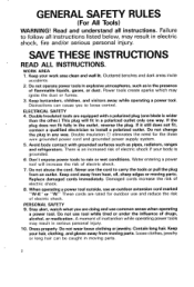
... instructions. Distractions can be caught in the presence of electric shock. 7. Replace damaged cords immediately. Read and understand all instructions listed below, may ignite the dust or fumes. 3.Keep bystanders, children, and visitors away while operating a power tool. Do not change the plug in any way. Do not abuse the cord. ELECTRICAL SAFETY 4. Keep cord away from heat, oil, sharp edges or moving parts. 2 SAVE THESE INSTRUCTIONS READ ALL INSTRUCTIONS...
... instructions. Distractions can be caught in the presence of electric shock. 7. Replace damaged cords immediately. Read and understand all instructions listed below, may ignite the dust or fumes. 3.Keep bystanders, children, and visitors away while operating a power tool. Do not change the plug in any way. Do not abuse the cord. ELECTRICAL SAFETY 4. Keep cord away from heat, oil, sharp edges or moving parts. 2 SAVE THESE INSTRUCTIONS READ ALL INSTRUCTIONS...
Owners Manual
Page 3
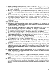
.... 17. Use safety equipment. TOOL USE AND CARE 1 5 . Use clamps or other untrained persons. Use the correct tool for your body is unstable and may lead to loss of children and other practical way t o secure and support the workpiece t o a stable platform. Do not use only identical replacement parts. Disconnect the plug from the power source before plugging in the hands of parts, and any adjustments, changing accessories, or...
.... 17. Use safety equipment. TOOL USE AND CARE 1 5 . Use clamps or other untrained persons. Use the correct tool for your body is unstable and may lead to loss of children and other practical way t o secure and support the workpiece t o a stable platform. Do not use only identical replacement parts. Disconnect the plug from the power source before plugging in the hands of parts, and any adjustments, changing accessories, or...
Owners Manual
Page 4
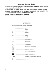
Always lead the power supply cord away from the tool towards the rear. . 3.Do not touch the blade or the workpiece immediately after operation; volts amperes herts hours minutes alternating current direct current no load speed alternating or direct current Class I1 Construction splash-proof construction watertight construction revolutions or reciprocation per minute U number of blow 4 SAVE THESE INSTRUCTIONS. Specific Safety Rules 1. SYMBOLS The followings...
Always lead the power supply cord away from the tool towards the rear. . 3.Do not touch the blade or the workpiece immediately after operation; volts amperes herts hours minutes alternating current direct current no load speed alternating or direct current Class I1 Construction splash-proof construction watertight construction revolutions or reciprocation per minute U number of blow 4 SAVE THESE INSTRUCTIONS. Specific Safety Rules 1. SYMBOLS The followings...
Owners Manual
Page 5
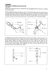
... punch is switched off and unplugged before removing or installing the punch and die. Then install the die holder on the die holder. Remove the die holder from the die holder. Remove the die from the tool. Tighten the bolts to secure the die holder. Tighten the lock nut to secure the die. Always replace the punch and die as a set. Use the hex wrench to loosen the screw which secure...
... punch is switched off and unplugged before removing or installing the punch and die. Then install the die holder on the die holder. Remove the die holder from the die holder. Remove the die from the tool. Tighten the bolts to secure the die holder. Tighten the lock nut to secure the die. Always replace the punch and die as a set. Use the hex wrench to loosen the screw which secure...
Owners Manual
Page 6
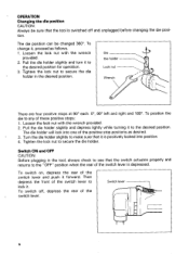
... the front of these positive stops: 1. Loosen the lock nut with the wrench provided. 2. Pull the die holder slightly and depress lightly while turning it to any of the switch lever to the desired position. The die holder will lock into position. 4. Switch lever 6 tion. Tighten the lock nut to secure the die holder. Tighten the lock nut to secure the die holder in the desired position. OPERATION Changing the die position CAUTION...
... the front of these positive stops: 1. Loosen the lock nut with the wrench provided. 2. Pull the die holder slightly and depress lightly while turning it to any of the switch lever to the desired position. The die holder will lock into position. 4. Switch lever 6 tion. Tighten the lock nut to secure the die holder. Tighten the lock nut to secure the die holder in the desired position. OPERATION Changing the die position CAUTION...
Owners Manual
Page 7
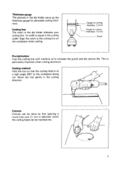
... Cutting method Hold the tool so that the cutting head is equal to increase the punch and die service life. Align the notch to the workpiece being cut. Move the tool gently in the die holder indicates your cutting line. ness. Its width is at a right angle (90") to the cutting line on the workpiece when cutting. - Cutting line The notch in the cutting direction...
... Cutting method Hold the tool so that the cutting head is equal to increase the punch and die service life. Align the notch to the workpiece being cut. Move the tool gently in the die holder indicates your cutting line. ness. Its width is at a right angle (90") to the cutting line on the workpiece when cutting. - Cutting line The notch in the cutting direction...
Owners Manual
Page 8
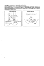
I From the top view From the side view Cutting at an angle to grooves Cutting head should be at a right angle (90")to the cutting surface as shown in corrugated or trapezoidal sheet metals. Cuttingthe corrugated or trapezoidalsheet metals Set the die position so that the die faces the cutting direction either when cutting a t an angle or perpendicular to cutting surface. From the side view sheet metal 8 Always hold the tool body parallel to the grooves with the cuttina head at a right angle (90") to grooves in Fig.
I From the top view From the side view Cutting at an angle to grooves Cutting head should be at a right angle (90")to the cutting surface as shown in corrugated or trapezoidal sheet metals. Cuttingthe corrugated or trapezoidalsheet metals Set the die position so that the die faces the cutting direction either when cutting a t an angle or perpendicular to cutting surface. From the side view sheet metal 8 Always hold the tool body parallel to the grooves with the cuttina head at a right angle (90") to grooves in Fig.
Owners Manual
Page 9
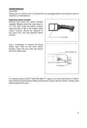
... secure the brush holder caps. Limit mark ,-Brush holder cap Screwdriver / To maintain product SAFETY AND RELIABILITY, repairs, any other maintenance or adjustment should be sure that the tool is switched off and unplugged before attempting to remove the brush holder caps. Replacing carbon brushes Remove and check the carbon brushes the same time. Use a screwdriver to perform inspection or maintenance. MAINTENANCE CAUTION: Always be performed by Makita Authorized or Factory Service Centers, always using Makita replacement parts. 9 Use only identical carbon brushes.
... secure the brush holder caps. Limit mark ,-Brush holder cap Screwdriver / To maintain product SAFETY AND RELIABILITY, repairs, any other maintenance or adjustment should be sure that the tool is switched off and unplugged before attempting to remove the brush holder caps. Replacing carbon brushes Remove and check the carbon brushes the same time. Use a screwdriver to perform inspection or maintenance. MAINTENANCE CAUTION: Always be performed by Makita Authorized or Factory Service Centers, always using Makita replacement parts. 9 Use only identical carbon brushes.
Owners Manual
Page 10
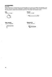
The use with your Makita tool specified in the proper and intended manner. A-I 5067 *Hex wrench Part No. 783208-8 u *Wrench 32 Part No. 781013-7 10 Die Part No. ACCESSORIES CAUTION: . The accessories or attachments should be used only in this manual. These accessories or attachments are recommended for use of any other accessories or attachments might present a risk of injury to persons. A-I 5051 *Punch Part No.
The use with your Makita tool specified in the proper and intended manner. A-I 5067 *Hex wrench Part No. 783208-8 u *Wrench 32 Part No. 781013-7 10 Die Part No. ACCESSORIES CAUTION: . The accessories or attachments should be used only in this manual. These accessories or attachments are recommended for use of any other accessories or attachments might present a risk of injury to persons. A-I 5051 *Punch Part No.
Owners Manual
Page 11
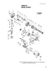
NIBBLER Model JN1601 Nav.--29-'94 EN d Note: The switch, noise suppressor and other part configurations may differ from country to country. 11
NIBBLER Model JN1601 Nav.--29-'94 EN d Note: The switch, noise suppressor and other part configurations may differ from country to country. 11
Owners Manual
Page 12
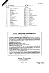
... period, return the COMPLETE tool, freight prepaid, to country stopper Pin 6 Ram Punch Holder Hex Socket Head Bolt M 5 x 8 Punch Dle One Holder Hex Socket Head Bolt M 3 x 1 2 Lock Nut Tapping Screw Flange PT 4 x 6 5 Makits Label Brush Holder Carbon Brush Brush Holder Cap Switch COmpreSSlOn S p r W 4 Switch Lever S"PP0lt Cord Guard Cord Strain Relief Tapping Screw 4 x 1 8 Rear Cover Tappinq Screw Flange PT 4 x 3 5 --< MAKITA LIMED ONE YEAR WARRANTY Warranty Policy Every Makita tool is caused by others: repairs are required because of normal...
... period, return the COMPLETE tool, freight prepaid, to country stopper Pin 6 Ram Punch Holder Hex Socket Head Bolt M 5 x 8 Punch Dle One Holder Hex Socket Head Bolt M 3 x 1 2 Lock Nut Tapping Screw Flange PT 4 x 6 5 Makits Label Brush Holder Carbon Brush Brush Holder Cap Switch COmpreSSlOn S p r W 4 Switch Lever S"PP0lt Cord Guard Cord Strain Relief Tapping Screw 4 x 1 8 Rear Cover Tappinq Screw Flange PT 4 x 3 5 --< MAKITA LIMED ONE YEAR WARRANTY Warranty Policy Every Makita tool is caused by others: repairs are required because of normal...
Parts Breakdown
Page 2
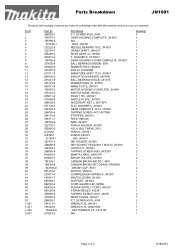
...-8 810247-6 Part Name P.T. BOLT M5X8, 2012 PUNCH, JN1601 PUNCH,JN1601 .DIE, JN1601 DIE HOLDER, JN1601 HEX SOCKET HEAD BOLT M3X12, JN1601 LOCK NUT, JN1601 TAPPING SCREW 4X65, HP2030 MAKITA LABEL, DA3010F BRUSH HOLDER, JN1601 CARBON BRUSH 408 SET, 3901 CARBON BRUSH SET CB-408, KP0800K BRUSH CAP , 9031 SWITCH, 9564CV COMPRESSION SPRING 4, JN1601 SWITCH LEVER, JN1601 SUPPORT, JN1601 CORD GUARD 8-90, 9005B POWER SUPPLY CORD, JN1601 STRAIN RELIEF, 4323K TAPPING SCREW 4X18, 4323K REAR COVER, JN1601 P.T. SCREW 4X35, 4304 WRENCH 32, JN1601 WRENCH 32, UM401DW HEX WRENCH 2.5, LS1016L N/A Quantity...
...-8 810247-6 Part Name P.T. BOLT M5X8, 2012 PUNCH, JN1601 PUNCH,JN1601 .DIE, JN1601 DIE HOLDER, JN1601 HEX SOCKET HEAD BOLT M3X12, JN1601 LOCK NUT, JN1601 TAPPING SCREW 4X65, HP2030 MAKITA LABEL, DA3010F BRUSH HOLDER, JN1601 CARBON BRUSH 408 SET, 3901 CARBON BRUSH SET CB-408, KP0800K BRUSH CAP , 9031 SWITCH, 9564CV COMPRESSION SPRING 4, JN1601 SWITCH LEVER, JN1601 SUPPORT, JN1601 CORD GUARD 8-90, 9005B POWER SUPPLY CORD, JN1601 STRAIN RELIEF, 4323K TAPPING SCREW 4X18, 4323K REAR COVER, JN1601 P.T. SCREW 4X35, 4304 WRENCH 32, JN1601 WRENCH 32, UM401DW HEX WRENCH 2.5, LS1016L N/A Quantity...


