
Owners Manual
Page 2
... conditions. Avoid accidental starting. Read and understand all times. Electrical Safety 4. Do not change without notice. • Specifications may result in tools that is off before turning the tool on. Damaged cords increase the risk of electric shock. 7. Replace damaged cords immediately. Keep your hair, clothing, and gloves away from country to country. • Weight according to follow all instructions listed below, may ignite...
... conditions. Avoid accidental starting. Read and understand all times. Electrical Safety 4. Do not change without notice. • Specifications may result in tools that is off before turning the tool on. Damaged cords increase the risk of electric shock. 7. Replace damaged cords immediately. Keep your hair, clothing, and gloves away from country to country. • Weight according to follow all instructions listed below, may ignite...
Owners Manual
Page 3
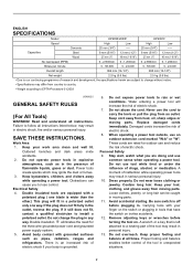
... and support the workpiece to hammer drill safety rules. Use safety equipment. Properly maintained tools with care. An undersized cord will do the job better and safer at the rate for your extension cord is below when using . Store idle tools out of reach of children and other condition that are easier to follow Maintenance instructions may create a risk of parts, and any adjustments, changing accessories, or...
... and support the workpiece to hammer drill safety rules. Use safety equipment. Properly maintained tools with care. An undersized cord will do the job better and safer at the rate for your extension cord is below when using . Store idle tools out of reach of children and other condition that are easier to follow Maintenance instructions may create a risk of parts, and any adjustments, changing accessories, or...
Owners Manual
Page 4
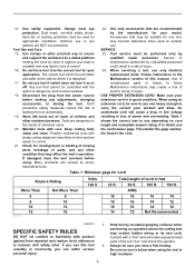
... the symbols used for tool. ・ volts ・ amperes ・ hertz ・ alternating current ・ no load speed ・ Class II Construction ・ revolutions or reciprocation per minute ・ number of blow FUNCTIONAL DESCRIPTION CAUTION: • Always be sure that the tool is increased by increasing pressure on the switch trigger. Lock button 2. Lower 002990 CAUTION: • Before plugging in this instruction manual may...
... the symbols used for tool. ・ volts ・ amperes ・ hertz ・ alternating current ・ no load speed ・ Class II Construction ・ revolutions or reciprocation per minute ・ number of blow FUNCTIONAL DESCRIPTION CAUTION: • Always be sure that the tool is increased by increasing pressure on the switch trigger. Lock button 2. Lower 002990 CAUTION: • Before plugging in this instruction manual may...
Owners Manual
Page 5
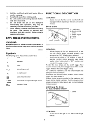
Reversing switch lever A CAUTION: • Use the speed change knob only after the tool comes to a complete stop . CAUTION: • Always check the direction of rotation before carrying out any work on the tool body points toward the "I " and "II" position, the tool may lower the illumination. If it off. ASSEMBLY CAUTION: • Always be damaged. Installing side grip (auxiliary handle) 1 3 2 4 1. Protrusions 002693 5 Release the trigger to turn it...
Reversing switch lever A CAUTION: • Use the speed change knob only after the tool comes to a complete stop . CAUTION: • Always check the direction of rotation before carrying out any work on the tool body points toward the "I " and "II" position, the tool may lower the illumination. If it off. ASSEMBLY CAUTION: • Always be damaged. Installing side grip (auxiliary handle) 1 3 2 4 1. Protrusions 002693 5 Release the trigger to turn it...
Owners Manual
Page 6
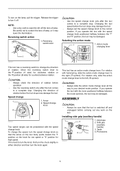
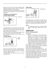
... and switch handle during operations. Installing or removing drill bit For Model HP2050, HP2050F 1. For Model HP2051F 1. NOTE: • The depth gauge cannot be secured at the desired location for drilling holes of the tool and potentially severe injury. Always use "rotation with chips or particles. Position the bit at any position. Do not apply more pressure when the hole becomes clogged with hammering" action. After using the chuck key, be...
... and switch handle during operations. Installing or removing drill bit For Model HP2050, HP2050F 1. For Model HP2051F 1. NOTE: • The depth gauge cannot be secured at the desired location for drilling holes of the tool and potentially severe injury. Always use "rotation with chips or particles. Position the bit at any position. Do not apply more pressure when the hole becomes clogged with hammering" action. After using the chuck key, be...
Owners Manual
Page 7
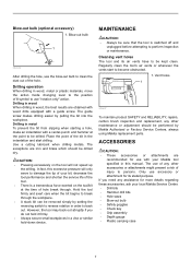
... accessories, ask your bit, decrease the tool performance and shorten the service life of your local Makita Service Center. • Drill bits • Hammer drill bits • Hole saws • Blow-out bulb • Safety goggles • Chuck key • Grip assembly • Depth gauge • Plastic carrying case 7 Use a cutting lubricant when drilling metals. Cleaning vent holes The tool and its stated purpose. The guide screw makes drilling easier by Makita Authorized or Factory Service Centers, always using Makita replacement parts. MAINTENANCE...
... accessories, ask your bit, decrease the tool performance and shorten the service life of your local Makita Service Center. • Drill bits • Hammer drill bits • Hole saws • Blow-out bulb • Safety goggles • Chuck key • Grip assembly • Depth gauge • Plastic carrying case 7 Use a cutting lubricant when drilling metals. Cleaning vent holes The tool and its stated purpose. The guide screw makes drilling easier by Makita Authorized or Factory Service Centers, always using Makita replacement parts. MAINTENANCE...

Owners Manual
Page 8
... Makita's Factory or Authorized Service Centers. IN NO EVENT SHALL MAKITA BE LIABLE FOR ANY INDIRECT, INCIDENTAL OR CONSEQUENTIAL DAMAGES FROM THE SALE OR USE OF THE PRODUCT. This Warranty gives you specific legal rights, and you may not apply to one year period, return the COMPLETE tool, freight prepaid, to you . This Warranty does not apply where: repairs...
... Makita's Factory or Authorized Service Centers. IN NO EVENT SHALL MAKITA BE LIABLE FOR ANY INDIRECT, INCIDENTAL OR CONSEQUENTIAL DAMAGES FROM THE SALE OR USE OF THE PRODUCT. This Warranty gives you specific legal rights, and you may not apply to one year period, return the COMPLETE tool, freight prepaid, to you . This Warranty does not apply where: repairs...
Parts Breakdown
Page 2
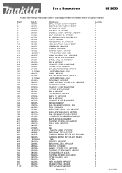
...,HR2455 BAFFLE PLATE, HP2050F TAPPING SCREW 4X65, HP2030 FIELD 115V, HP2050F N/A N/A MAKITA LABEL, DA3010F BRUSH HOLDER,HP2050F CARBON BRUSH SET CB-407, BO5030K CARBON BRUSH SET CB-407, FS4200 N/A SPACER, HP2050F BRUSH HOLDER, HP2050F SWITCH, HP2050F HANDLE COVER CPL., HP2050F TAPPING SCREW M4X25, HM1800 STRAIN RELIEF, 4323K TAPPING SCREW 4X18, 4323K CORD GUARD 8, 6824 CORD HEX. BEARING 6202LLB, NHP1310 CAM A HP2050F RING SPRING 11, HP2050F HEX. WASHER, HP2050F RUBBER PIN 4, HR2400 DEPTH GAUGE,HP2050F Page...
...,HR2455 BAFFLE PLATE, HP2050F TAPPING SCREW 4X65, HP2030 FIELD 115V, HP2050F N/A N/A MAKITA LABEL, DA3010F BRUSH HOLDER,HP2050F CARBON BRUSH SET CB-407, BO5030K CARBON BRUSH SET CB-407, FS4200 N/A SPACER, HP2050F BRUSH HOLDER, HP2050F SWITCH, HP2050F HANDLE COVER CPL., HP2050F TAPPING SCREW M4X25, HM1800 STRAIN RELIEF, 4323K TAPPING SCREW 4X18, 4323K CORD GUARD 8, 6824 CORD HEX. BEARING 6202LLB, NHP1310 CAM A HP2050F RING SPRING 11, HP2050F HEX. WASHER, HP2050F RUBBER PIN 4, HR2400 DEPTH GAUGE,HP2050F Page...
Technical Reference
Page 1
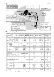
...) LED job light Reverse switch Protection from country to country. drill bit 5 - 19mm * Metal borer 14 - 35mm * Keyless drill chuck * Drill bit for metal 13mm * Depth guide * Drill chuck set * Drill bit for wood 40mm * Wrench 9 * Side grip set * Center drill bit for hole saw 16 - 90mm * Blow-out bulb * Type 43 drill stand * Chuck key S-13 (for the tool shown may differ from electric shock No Yes No Yes Yes by double insulation Cord length : m ( ft...
...) LED job light Reverse switch Protection from country to country. drill bit 5 - 19mm * Metal borer 14 - 35mm * Keyless drill chuck * Drill bit for metal 13mm * Depth guide * Drill chuck set * Drill bit for wood 40mm * Wrench 9 * Side grip set * Center drill bit for hole saw 16 - 90mm * Blow-out bulb * Type 43 drill stand * Chuck key S-13 (for the tool shown may differ from electric shock No Yes No Yes Yes by double insulation Cord length : m ( ft...
Technical Reference
Page 2
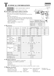
only HP2050F/ HP2051F Comparison of drill bit Lever for F/R change Palm fitting soft grip Variable speed control switch with torque limiter for protection of user and mechanism from accidental lock of products Cord guard is not only tough but also very flexible to change the working point. MAKITA Specifications HP2050 (F) HP2051 (F) HP2032 HP2033 Power Input : W 720 720 No load speed (High) : (min -1= rpm) (Low) 0 - 2,900 0 - 1,200 0 - 2,900 0 - 850 Blows per...
only HP2050F/ HP2051F Comparison of drill bit Lever for F/R change Palm fitting soft grip Variable speed control switch with torque limiter for protection of user and mechanism from accidental lock of products Cord guard is not only tough but also very flexible to change the working point. MAKITA Specifications HP2050 (F) HP2051 (F) HP2032 HP2033 Power Input : W 720 720 No load speed (High) : (min -1= rpm) (Low) 0 - 2,900 0 - 1,200 0 - 2,900 0 - 850 Blows per...
Technical Reference
Page 3
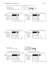
...) Douglas fir * Working mode : Drill / High Speed * When hammer drilling with :ø 24 mm (15/16") bit MAKITA HP2050(F)/HP2051(F) Competitor A Model A-1 Competitor A Model A-2 120 100 120 * Working mode : Drill / Low Speed * When hammer drilling with ø 36mm (1-7/16") bit MAKITA HP2050(F)/HP2051(F) Competitor A Model A-1 Competitor A Model A-2 125 100 100 0 50 100 150 200 0 50 100 150 200 Comparison of working rate Numbers in chart below are relative values when setting Model A-1 's capacity as...
...) Douglas fir * Working mode : Drill / High Speed * When hammer drilling with :ø 24 mm (15/16") bit MAKITA HP2050(F)/HP2051(F) Competitor A Model A-1 Competitor A Model A-2 120 100 120 * Working mode : Drill / Low Speed * When hammer drilling with ø 36mm (1-7/16") bit MAKITA HP2050(F)/HP2051(F) Competitor A Model A-1 Competitor A Model A-2 125 100 100 0 50 100 150 200 0 50 100 150 200 Comparison of working rate Numbers in chart below are relative values when setting Model A-1 's capacity as...
Technical Reference
Page 4
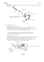
.... In case of spindle with No.1R139 "drill chuck extractor" which No.1R224 "ratchet head" is attached. Preset the torque level of gear housing. Repair P 4 / 17 < 1 > Lubrication Apply MAKITA grease N No.1 to the following portions marked with black triangle to protect parts and machine from spindle. Gear housing Spur gear 29-37 Fig. 1 Change lever B < 2 >Assembling and disassembling ( 1 ) Disassembling drill chuck See Fig. 2. 1. Insert No.1R298 "hex wrench" into drill chuck and...
.... In case of spindle with No.1R139 "drill chuck extractor" which No.1R224 "ratchet head" is attached. Preset the torque level of gear housing. Repair P 4 / 17 < 1 > Lubrication Apply MAKITA grease N No.1 to the following portions marked with black triangle to protect parts and machine from spindle. Gear housing Spur gear 29-37 Fig. 1 Change lever B < 2 >Assembling and disassembling ( 1 ) Disassembling drill chuck See Fig. 2. 1. Insert No.1R298 "hex wrench" into drill chuck and...
Technical Reference
Page 5
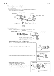
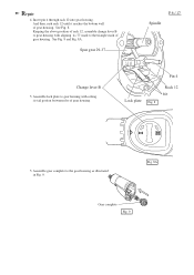
Repair ( 3) Disassembling gear section See Fig. 3. 1. Pull out lock plate. 3. Insert change plate B to gear housing as illustrated Fig. 4 below. Set the above assembled one to "( 6) Assembling bearing retainer 20-36 and oil seal 19" at the same time, assemble rack 12 w/ change plate B into rack 12 as illustrated Fig. 6 right. Spur gear 29-37 4. Gear housing Spur gear 29-37 Lock plate Gear housing cover P 5 / 17 Change lever B Rack 12 Pin Change plate B Fig. 3 ( 4) Assembling gear section 1. Bearing...
Repair ( 3) Disassembling gear section See Fig. 3. 1. Pull out lock plate. 3. Insert change plate B to gear housing as illustrated Fig. 4 below. Set the above assembled one to "( 6) Assembling bearing retainer 20-36 and oil seal 19" at the same time, assemble rack 12 w/ change plate B into rack 12 as illustrated Fig. 6 right. Spur gear 29-37 4. Gear housing Spur gear 29-37 Lock plate Gear housing cover P 5 / 17 Change lever B Rack 12 Pin Change plate B Fig. 3 ( 4) Assembling gear section 1. Bearing...
Technical Reference
Page 6
... gear housing with setting its "I" mark to the triangle mark of gear housing. And then, rush rack 12 until it reaches the bottom wall of gear housing. See Fig. 8. Assemble lock plate to the gear housing as illustrated in Fig. 9. See Fig. 8 and Fig. 8A. Pin 4 Lock plate Fig. 8 Rack 12 Rib 5. Insert pin 4 through rack 12 into gear housing. Spur gear 29-37 P 6 / 17 Spindle Change lever B 5. Assemble gear...
... gear housing with setting its "I" mark to the triangle mark of gear housing. And then, rush rack 12 until it reaches the bottom wall of gear housing. See Fig. 8. Assemble lock plate to the gear housing as illustrated in Fig. 9. See Fig. 8 and Fig. 8A. Pin 4 Lock plate Fig. 8 Rack 12 Rib 5. Insert pin 4 through rack 12 into gear housing. Spur gear 29-37 P 6 / 17 Spindle Change lever B 5. Assemble gear...

Technical Reference
Page 7
..., and assemble oil seal 19 pressing with flat head screwdriver. 1R292 Wrench for bearing retainer Remodel by grinding this portion to be removed from gear housing. Arbor press 1R030 Bearing setting pipe Oil seal 19 1R292 Wrench for bearing retainer Loosening Fig. 11 ( 6) Assembling bearing retainer 20-36 and oil seal 19 1. Turn 1R292 "wrench for bearing retainer" by turning it on the spindle head. Because it on spindle head...
..., and assemble oil seal 19 pressing with flat head screwdriver. 1R292 Wrench for bearing retainer Remodel by grinding this portion to be removed from gear housing. Arbor press 1R030 Bearing setting pipe Oil seal 19 1R292 Wrench for bearing retainer Loosening Fig. 11 ( 6) Assembling bearing retainer 20-36 and oil seal 19 1. Turn 1R292 "wrench for bearing retainer" by turning it on the spindle head. Because it on spindle head...

Technical Reference
Page 8
... spring 15-24 Fig. 16B After removing bearing retainer 20-36 and oil seal 19, disassemble ring spring 11 from spindle as illustrated in Fig 14. So, cam A, ball bearing 6202LLB, cup washer 15 and conical compression spring 15-24 can be assembled as illustrated in Fig. 15. And disassemble spindle section by pulling out from the drill chuck side of gear...
... spring 15-24 Fig. 16B After removing bearing retainer 20-36 and oil seal 19, disassemble ring spring 11 from spindle as illustrated in Fig 14. So, cam A, ball bearing 6202LLB, cup washer 15 and conical compression spring 15-24 can be assembled as illustrated in Fig. 15. And disassemble spindle section by pulling out from the drill chuck side of gear...

Technical Reference
Page 14
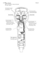
... from cord guard side) Fix Lead wire (black) connecting field terminals A and B, with lead holder the lead wires passed through this portion, with lead holder Noise suppressor LED circuit Switch Fix the lead wires (white) of LED circuit, with lead holder. A LED Fig. B LED circuit Lead wire (blue ) of power supply cord * Grounding lead wire (transparent) for connecting to be set in the illustrated position. Fix the...
... from cord guard side) Fix Lead wire (black) connecting field terminals A and B, with lead holder the lead wires passed through this portion, with lead holder Noise suppressor LED circuit Switch Fix the lead wires (white) of LED circuit, with lead holder. A LED Fig. B LED circuit Lead wire (blue ) of power supply cord * Grounding lead wire (transparent) for connecting to be set in the illustrated position. Fix the...
Technical Reference
Page 15
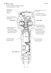
... The electrical parts marked with * have to insulated terminal Fix with lead holder the lead wires passed through this portion Switch Fix Lead wire (black) connecting field terminals A and B, with lead holder. Fix the following lead wires with this lead holder. * Switch lead wire (red) for connecting to brush holder * Lead wire (black) connecting field terminals A and B Fix with lead holder the lead wires passed through this lead holder. * Switch lead wire (blue...
... The electrical parts marked with * have to insulated terminal Fix with lead holder the lead wires passed through this portion Switch Fix Lead wire (black) connecting field terminals A and B, with lead holder. Fix the following lead wires with this lead holder. * Switch lead wire (red) for connecting to brush holder * Lead wire (black) connecting field terminals A and B Fix with lead holder the lead wires passed through this lead holder. * Switch lead wire (blue...
Technical Reference
Page 16
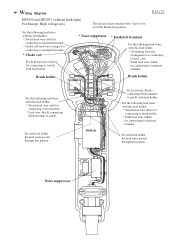
Wiring diagram HP2050 and HP2051 (without flash light) For Great Britain, low voltage Choke coil Set choke coil in the position illustrated. Brush holder Fix Lead wire (black) connecting field terminals A and B, with lead holder. Fix grounding lead wire (transparent) for connecting to field core, with lead holder. Fix the following lead wires with this lead holder. * Switch lead wire (red) for connecting to brush holder * Lead wire (black) connecting field terminals...
Wiring diagram HP2050 and HP2051 (without flash light) For Great Britain, low voltage Choke coil Set choke coil in the position illustrated. Brush holder Fix Lead wire (black) connecting field terminals A and B, with lead holder. Fix grounding lead wire (transparent) for connecting to field core, with lead holder. Fix the following lead wires with this lead holder. * Switch lead wire (red) for connecting to brush holder * Lead wire (black) connecting field terminals...
Technical Reference
Page 17
Brush holder Fix the following lead wires with this lead holder. * Switch lead wire (red) for connecting to switch Fix with lead holder the lead wires passed through this portion Noise suppressor Noise suppressor is not used in some countries. Brush holder Fix the following lead wires with this lead holder. * Switch lead wire (blue) for connecting to brush holder * Field lead wire (white) for connecting to switch, with lead holder. Wiring diagram HP2050 and HP2051 (without flash...
Brush holder Fix the following lead wires with this lead holder. * Switch lead wire (red) for connecting to switch Fix with lead holder the lead wires passed through this portion Noise suppressor Noise suppressor is not used in some countries. Brush holder Fix the following lead wires with this lead holder. * Switch lead wire (blue) for connecting to brush holder * Field lead wire (white) for connecting to switch, with lead holder. Wiring diagram HP2050 and HP2051 (without flash...


