Owners Manual
Page 1
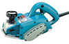
Curved Planer 1I O mm (4-3/8") MODEL 1002BA INSTRUCTION MANUAL Planing width 110 mm (4-3/8") Planing depth 4 mm (5/32") No load speed (RPM) 15,000 Overall length 339 mm (13-1/32") Net weight 5 4 kg (11 9 Ibs)
Curved Planer 1I O mm (4-3/8") MODEL 1002BA INSTRUCTION MANUAL Planing width 110 mm (4-3/8") Planing depth 4 mm (5/32") No load speed (RPM) 15,000 Overall length 339 mm (13-1/32") Net weight 5 4 kg (11 9 Ibs)

Owners Manual
Page 2
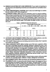
..., ELECTRIC SHOCK, AND PERSONAL INJURY, INCLUDING THE FOLLOWING: READ ALL INSTRUCTIONS. 1. Cluttered areas and benches invite injuries. 2. CONSIDER WORK AREA ENVIRONMENT. Keep work . Don't use , before servicing, and when changing accessories, such as blades, bits, cutters. - All visitors should be kept away from receptacle. Don't let visitors contact tool or extension cord. - 4. STORE IDLE TOOLS. USE RIGHT TOOL. for example, don't use , tools should be stored in use circular saw...
..., ELECTRIC SHOCK, AND PERSONAL INJURY, INCLUDING THE FOLLOWING: READ ALL INSTRUCTIONS. 1. Cluttered areas and benches invite injuries. 2. CONSIDER WORK AREA ENVIRONMENT. Keep work . Don't use , before servicing, and when changing accessories, such as blades, bits, cutters. - All visitors should be kept away from receptacle. Don't let visitors contact tool or extension cord. - 4. STORE IDLE TOOLS. USE RIGHT TOOL. for example, don't use , tools should be stored in use circular saw...
Owners Manual
Page 3
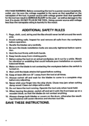
..., usethe next heavier gage. The smaller the gage number, the heavier the cord. Watch what you aretired. 19. Don't operate tool when you are removed from tool before turning it will draw. Have defective switches replaced by authorized service center. Don't use outdoors and so marked. 18. GUARD AGAINST ELECTRIC SHOCK. For example; REPIACEMENTPARTS.When servicing, useonly identicalreplacementparts. 22. POLARIZEDPLUGS. Hthe plug does not...
..., usethe next heavier gage. The smaller the gage number, the heavier the cord. Watch what you aretired. 19. Don't operate tool when you are removed from tool before turning it will draw. Have defective switches replaced by authorized service center. Don't use outdoors and so marked. 18. GUARD AGAINST ELECTRIC SHOCK. For example; REPIACEMENTPARTS.When servicing, useonly identicalreplacementparts. 22. POLARIZEDPLUGS. Hthe plug does not...
Owners Manual
Page 4
... blades t o come t o a complete stop before opera- Operate the tool only when hand-held. 14. Using a power sourcewith voltage lessthan the nameplate rating is the same as damaget o the tool. ADDITIONAL SAFETY RULES 1. Inspect for and remove all times. 11. Handle the blades very carefully. 4. Keep hands away from the tool at all nails from the workpiece before cutting. Before using the tool on . 9. Wait until the blade attains full speed...
... blades t o come t o a complete stop before opera- Operate the tool only when hand-held. 14. Using a power sourcewith voltage lessthan the nameplate rating is the same as damaget o the tool. ADDITIONAL SAFETY RULES 1. Inspect for and remove all times. 11. Handle the blades very carefully. 4. Keep hands away from the tool at all nails from the workpiece before cutting. Before using the tool on . 9. Wait until the blade attains full speed...
Owners Manual
Page 5
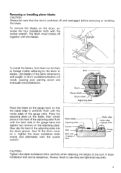
... inside edge of the gauge base and tighten two screws on the blade, then simply press in the heel of the adjusting plate flush with the blades. \ I base - \ / of the same dimensions and weight, or drum oscillation/vibration will result, causing poor planing action and eventually tool breakdown. The drum cover comes off and unplugged before removing or installing the blade. Place the adjusting plate on the adjusting plate. Tigkten...
... inside edge of the gauge base and tighten two screws on the blade, then simply press in the heel of the adjusting plate flush with the blades. \ I base - \ / of the same dimensions and weight, or drum oscillation/vibration will result, causing poor planing action and eventually tool breakdown. The drum cover comes off and unplugged before removing or installing the blade. Place the adjusting plate on the adjusting plate. Tigkten...

Owners Manual
Page 6
.... Adjusting depth of cut Depth of cut may be adjusted by simply turning the knob on the front of 300 mm, loosen the wing bolt on either side and raise the front base as far as it . 1 Wing bolt CAUTION: Before plugging in the lock button. Knob Adjusting front base The front base is factory-adjusted to secure the front base. Switch action To start the tool, simply pull the trigger...
.... Adjusting depth of cut Depth of cut may be adjusted by simply turning the knob on the front of 300 mm, loosen the wing bolt on either side and raise the front base as far as it . 1 Wing bolt CAUTION: Before plugging in the lock button. Knob Adjusting front base The front base is factory-adjusted to secure the front base. Switch action To start the tool, simply pull the trigger...
Owners Manual
Page 7
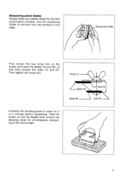
Sharpening planer blades Always keep your blades sharp for 2 or 3 minutes before sharpening. Wing nut Blade (A) Blade (6) Immerse the dressing stone in water for the best performance possible. Then tighten the wing nuts. Sharpening holder First, loosen the two wing nuts on the holder and insert the blades (A) and (B), so that the blades both contact the dressing stone for simultaneous sharpening at the same angle. Use the sharpening holder to remove nicks and produce a fine edge. Hold the holder so that they contact the sides (C) and (D). Side (C)
Sharpening planer blades Always keep your blades sharp for 2 or 3 minutes before sharpening. Wing nut Blade (A) Blade (6) Immerse the dressing stone in water for the best performance possible. Then tighten the wing nuts. Sharpening holder First, loosen the two wing nuts on the holder and insert the blades (A) and (B), so that the blades both contact the dressing stone for simultaneous sharpening at the same angle. Use the sharpening holder to remove nicks and produce a fine edge. Hold the holder so that they contact the sides (C) and (D). Side (C)
Owners Manual
Page 8
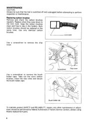
... Service Centers, always using Makita replacement parts. 8 Take out the worn carbon brushes, insert the new ones and secure the brush holder caps. Sdrewdriver Chipcover I Limit mark Use a screwdriver to remove the chip cover. 1 // Use a screwdriver to the limit mark. Both carbon brushes should be sure that the tool is switched off and unplugged before attempting to slip in the holders. I Brush holder cap \ To maintain product SAFETY and RELIABILITY, repairs, any other maintenance or adjustment...
... Service Centers, always using Makita replacement parts. 8 Take out the worn carbon brushes, insert the new ones and secure the brush holder caps. Sdrewdriver Chipcover I Limit mark Use a screwdriver to remove the chip cover. 1 // Use a screwdriver to the limit mark. Both carbon brushes should be sure that the tool is switched off and unplugged before attempting to slip in the holders. I Brush holder cap \ To maintain product SAFETY and RELIABILITY, repairs, any other maintenance or adjustment...
Owners Manual
Page 9
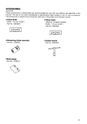
ACCESSORIES CAUTION These accessories or attachments are recommended for use with your Makita tool specified in this manual The use of any other accessories or attachments might present a risk of injury to persons The accessories or attachments should be used only in the proper and intended manner Planer blade Width 110 mm (4-3/8") Part No 793008-8 Planer blade (Material Tungsten-carbide) Width 110 m m (4-3/8") Part No 7930096 Sharpening holder assembly Part No. 123055-9 Socket wrench Part No. 782209-3 *Blade gauge Part No. 123062-2 9
ACCESSORIES CAUTION These accessories or attachments are recommended for use with your Makita tool specified in this manual The use of any other accessories or attachments might present a risk of injury to persons The accessories or attachments should be used only in the proper and intended manner Planer blade Width 110 mm (4-3/8") Part No 793008-8 Planer blade (Material Tungsten-carbide) Width 110 m m (4-3/8") Part No 7930096 Sharpening holder assembly Part No. 123055-9 Socket wrench Part No. 782209-3 *Blade gauge Part No. 123062-2 9

Owners Manual
Page 10
110 mm (4-318") CURVED PLANER Model 1002BA Seo.-ll-'97 US e Note: The switch and other part configurations may differ from country to country. 10
110 mm (4-318") CURVED PLANER Model 1002BA Seo.-ll-'97 US e Note: The switch and other part configurations may differ from country to country. 10
Owners Manual
Page 11
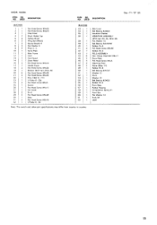
... 2 29 2 30 1 31 2 32 1 Pan Head Screw M4x50 Pan Head Screw M4x20 Chtp Cover Brush Holder Cap Carbon Brush Wing Bolt M6x25 Spring Washer 6 Flat Washer 6 Rivet 0 - 5 Name Plate Main Frame Cord Cord Guard Strain Relief Pan Head Screw M4x18 Handle Cover Pan Head Screw M4x30 Bracket [With Item 40 & 491 Pan Head Screw M5x28 Pan Head Screw M4x30 Poly V Belt 6 - 2 1 2 V Pulley 6 - 2 3 L Pan Head Screw M 4 x 6 Switch Pan Head Screw M4x12 Fan Guide Pin 6 Pan Head Screw M5x28 Base Pan Head Screw M5x18 V Pullev 6 - 30 MACHINE ~ 33 1 34...
... 2 29 2 30 1 31 2 32 1 Pan Head Screw M4x50 Pan Head Screw M4x20 Chtp Cover Brush Holder Cap Carbon Brush Wing Bolt M6x25 Spring Washer 6 Flat Washer 6 Rivet 0 - 5 Name Plate Main Frame Cord Cord Guard Strain Relief Pan Head Screw M4x18 Handle Cover Pan Head Screw M4x30 Bracket [With Item 40 & 491 Pan Head Screw M5x28 Pan Head Screw M4x30 Poly V Belt 6 - 2 1 2 V Pulley 6 - 2 3 L Pan Head Screw M 4 x 6 Switch Pan Head Screw M4x12 Fan Guide Pin 6 Pan Head Screw M5x28 Base Pan Head Screw M5x18 V Pullev 6 - 30 MACHINE ~ 33 1 34...

Owners Manual
Page 12
... MAKITA DISCLAIMS LIABILITY FOR ANY IMPLIED WARRANTIES, INCLUDING IMPLIED WARRANTIES OF "MERCHANTABILITY" AND "FITNESS FOR A SPECIFIC PURPOSE," AFTER THE ONE-YEAR TERM OF THIS WARRANTY. Makita Corporation 3-11-8, Sumiyoshi-cho, Anjo, Aichi 446 Japan 884054 - 065 PRINTED IN JAPAN 1997 - 10 - MAKITA LIMITEDONE YEAR WARRANTY Warranty Policy Every Makita tool is caused by others: repairs are required because of Makita's Factory or Authorized Service...
... MAKITA DISCLAIMS LIABILITY FOR ANY IMPLIED WARRANTIES, INCLUDING IMPLIED WARRANTIES OF "MERCHANTABILITY" AND "FITNESS FOR A SPECIFIC PURPOSE," AFTER THE ONE-YEAR TERM OF THIS WARRANTY. Makita Corporation 3-11-8, Sumiyoshi-cho, Anjo, Aichi 446 Japan 884054 - 065 PRINTED IN JAPAN 1997 - 10 - MAKITA LIMITEDONE YEAR WARRANTY Warranty Policy Every Makita tool is caused by others: repairs are required because of Makita's Factory or Authorized Service...
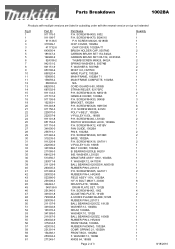
Parts Breakdown
Page 2
... FRAME COMPLETE, 1002BA N/A CORD GUARD 8-90, 9005B STRAIN RELIEF, 9217SPC P.H. SCREW M4X12, 4301BV FAN GUIDE, 1002BA PIN 6, 1002BA P.H. SCREW M4X18, N9501B HANDLE COVER, 1002BA P.H. BOLT M6X17, 2030S DRUM PLATE, 1002BA DRUM PLATE SET, 1912B P.H. WASHER 13, 1806B KNOB 64, 1806B Page 2 of 3 Quantity 1 1 1 1 1 2 1 1 2 2 2 4 1 1 1 1 1 1 2 1 3 1 6 2 1 1 2 1 1 1 2 2 1 2 1 1 1 1 1 1 1 1 2 1 1 8 1 1 4 2 1 1 1 1 1 1 1 1 1 1 1 1 1 1 8/18/2010 SCREW M4X50, 6302 P.H. SPRING 21, 1002BA FRONT BOX, 1002BA F. SCREW M4X70, BO4510 P.H. SCREW M4X30, 2412N POLY V-BELT, 1002BA V-PULLEY 6-23L...
... FRAME COMPLETE, 1002BA N/A CORD GUARD 8-90, 9005B STRAIN RELIEF, 9217SPC P.H. SCREW M4X12, 4301BV FAN GUIDE, 1002BA PIN 6, 1002BA P.H. SCREW M4X18, N9501B HANDLE COVER, 1002BA P.H. BOLT M6X17, 2030S DRUM PLATE, 1002BA DRUM PLATE SET, 1912B P.H. WASHER 13, 1806B KNOB 64, 1806B Page 2 of 3 Quantity 1 1 1 1 1 2 1 1 2 2 2 4 1 1 1 1 1 1 2 1 3 1 6 2 1 1 2 1 1 1 2 2 1 2 1 1 1 1 1 1 1 1 2 1 1 8 1 1 4 2 1 1 1 1 1 1 1 1 1 1 1 1 1 1 8/18/2010 SCREW M4X50, 6302 P.H. SPRING 21, 1002BA FRONT BOX, 1002BA F. SCREW M4X70, BO4510 P.H. SCREW M4X30, 2412N POLY V-BELT, 1002BA V-PULLEY 6-23L...


