
User Guide
Page 3
...following help resources for FAQ, technical guide, BIOS updates, driver updates, and other information: http://www.msi.com.tw/ Contact our technical staff at: support@msi.com.tw iii We take every care in this document, but no solution can be obtained from the user's manual, please contact your place of ...release Date August 2003 Technical Support If a problem arises with your system and no guarantee is given as to make changes without notice. Copyright Notice The material in the preparation of this document is the intellectual property of MICRO-STAR INTERNATIONAL. Our products are...
...following help resources for FAQ, technical guide, BIOS updates, driver updates, and other information: http://www.msi.com.tw/ Contact our technical staff at: support@msi.com.tw iii We take every care in this document, but no solution can be obtained from the user's manual, please contact your place of ...release Date August 2003 Technical Support If a problem arises with your system and no guarantee is given as to make changes without notice. Copyright Notice The material in the preparation of this document is the intellectual property of MICRO-STAR INTERNATIONAL. Our products are...
User Guide
Page 5
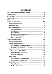
... 754 2-4 Installing AMD Athlon64 CPU Cooler Set 2-5 Memory 2-9 Introduction to DDR SDRAM 2-9 DDR DIMM Module Combination 2-10 Installing DDR Modules 2-10 Power Supply 2-11 ATX 20-Pin Power Connector: ATX 2-11 ATX 12V Power Connector: JPW1 2-11 Back Panel 2-12 Mouse Connector 2-12 Keyboard Connector 2-12 v Getting Started 1-1 Mainboard Specifications 1-2 Mainboard Layout 1-4 MSI Special Features 1-5 Color Management 1-5 Core Center 1-6 Core Cell™ Chip 1-8 Dynamic Overclocking Technology 1-9 Live BIOS™/Live Driver 1-10 D-Bracket...
... 754 2-4 Installing AMD Athlon64 CPU Cooler Set 2-5 Memory 2-9 Introduction to DDR SDRAM 2-9 DDR DIMM Module Combination 2-10 Installing DDR Modules 2-10 Power Supply 2-11 ATX 20-Pin Power Connector: ATX 2-11 ATX 12V Power Connector: JPW1 2-11 Back Panel 2-12 Mouse Connector 2-12 Keyboard Connector 2-12 v Getting Started 1-1 Mainboard Specifications 1-2 Mainboard Layout 1-4 MSI Special Features 1-5 Color Management 1-5 Core Center 1-6 Core Cell™ Chip 1-8 Dynamic Overclocking Technology 1-9 Live BIOS™/Live Driver 1-10 D-Bracket...
User Guide
Page 9
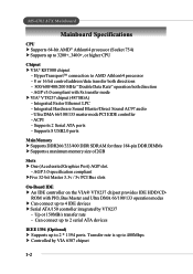
... - Can connect up to 2 serial ATA devices IEEE 1394 (Optional) h Supports up to 3200+, 3400+, or higher CPU Chipset h VIA® K8T800 chipset - Supports 8 USB2.0 ports Main Memory h Supports DDR266/333/400 DDR SDRAM for three 184-pin DDR DIMMs h Supports a maximum memory size of 2GB Slots h One (Accelerated Graphics Port) AGP slot. - AGP 3.0 specification compliant hFive 32-bit Master 3.3v / 5v PCI Bus slots On-Board IDE h An IDE controller on...
... - Can connect up to 2 serial ATA devices IEEE 1394 (Optional) h Supports up to 3200+, 3400+, or higher CPU Chipset h VIA® K8T800 chipset - Supports 8 USB2.0 ports Main Memory h Supports DDR266/333/400 DDR SDRAM for three 184-pin DDR DIMMs h Supports a maximum memory size of 2GB Slots h One (Accelerated Graphics Port) AGP slot. - AGP 3.0 specification compliant hFive 32-bit Master 3.3v / 5v PCI Bus slots On-Board IDE h An IDE controller on...

User Guide
Page 16
...disable the Dynamic OverClocking first. 1-9 By the way, if you need to be unstable or reboot incidentally, it will restore the default settings instead. When the motherboard detects CPU is still risky. We suggest user to make the program run huge amount of data like 3D games or the video process, and the CPU... to detect the load balance of CPU while running programs, it will speed up to enhance the overall performance. D.O.T Dynamic Overclocking Technology MSI Reminds You... Usually the Dynamic Overclocking Technology will be powered only when users' PC need to run smoothly ...
...disable the Dynamic OverClocking first. 1-9 By the way, if you need to be unstable or reboot incidentally, it will restore the default settings instead. When the motherboard detects CPU is still risky. We suggest user to make the program run huge amount of data like 3D games or the video process, and the CPU... to detect the load balance of CPU while running programs, it will speed up to enhance the overall performance. D.O.T Dynamic Overclocking Technology MSI Reminds You... Usually the Dynamic Overclocking Technology will be powered only when users' PC need to run smoothly ...

User Guide
Page 22
.... We do not have the heat sink and cooling fan, contact your components are installing the CPU, make sure the CPU has a heat sink and a cooling fan attached on the computer. Overclocking This motherboard is not recommended. Hardware Setup Central Processing Unit: CPU The mainboard supports AMD® Athlon64 processor. The mainboard uses a CPU socket called Socket-754 for 3 DIMM/DDR400 at MSI website. Overheating Overheating will...
.... We do not have the heat sink and cooling fan, contact your components are installing the CPU, make sure the CPU has a heat sink and a cooling fan attached on the computer. Overclocking This motherboard is not recommended. Hardware Setup Central Processing Unit: CPU The mainboard supports AMD® Athlon64 processor. The mainboard uses a CPU socket called Socket-754 for 3 DIMM/DDR400 at MSI website. Overheating Overheating will...
User Guide
Page 32
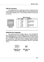
... IEEE 1394 ports. IEEE1394 Port (Standard) IEEE1394 Port (Mini) 2-13 The IEEE1394 high-speed serial bus components provide the enhanced PC connectivity for a wide range of devices, including consumer electronics audio/video (A/V) appliances, storage peripherals, other USB-compatible devices. The mini IEEE1394 port is designed for you to IEEE1394 devices without external power. Hardware Setup USB 2.0 Connectors The mainboard provides a UHCI (Universal Host Controller Interface) Universal Serial Bus root for attaching USB devices such as...
... IEEE 1394 ports. IEEE1394 Port (Standard) IEEE1394 Port (Mini) 2-13 The IEEE1394 high-speed serial bus components provide the enhanced PC connectivity for a wide range of devices, including consumer electronics audio/video (A/V) appliances, storage peripherals, other USB-compatible devices. The mini IEEE1394 port is designed for you to IEEE1394 devices without external power. Hardware Setup USB 2.0 Connectors The mainboard provides a UHCI (Universal Host Controller Interface) Universal Serial Bus root for attaching USB devices such as...

User Guide
Page 36
..., LAN, USB Ports, IR module and CPU/System/Power Supply FAN. If the chassis is opened, the switch will record this status and show a warning message on the screen. The system will be short. You must enter the BIOS utility and clear the record. Pin Signal 1 NC 2 NC 3 VCC5 4 GND 5 IRTX 6 IRRX JIR1 2 6 1 5 Chassis Intrusion Switch Connector: JCASE1 This connector is compliant with Intel® Front Panel I/O Connectivity Design Guide. Hardware Setup Connectors The mainboard provides connectors to connect...
..., LAN, USB Ports, IR module and CPU/System/Power Supply FAN. If the chassis is opened, the switch will record this status and show a warning message on the screen. The system will be short. You must enter the BIOS utility and clear the record. Pin Signal 1 NC 2 NC 3 VCC5 4 GND 5 IRTX 6 IRRX JIR1 2 6 1 5 Chassis Intrusion Switch Connector: JCASE1 This connector is compliant with Intel® Front Panel I/O Connectivity Design Guide. Hardware Setup Connectors The mainboard provides connectors to connect...
User Guide
Page 39
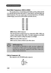
... hard disk documentation supplied by hard disk vendors for future BIOS) and other devices. If you install two hard disks on cable, you must configure second hard drive to Slave mode by setting its jumper. MSI Reminds You... Refer to Slave mode by setting the jumper accordingly. You can connect up to IDE1. IDE1 IDE2 IDE1 (Primary IDE Connector) The first hard drive should always be connected to four hard disk drives, CD-ROM, 120MB Floppy (reserved for jumper setting instructions. IDE1 can also connect...
... hard disk documentation supplied by hard disk vendors for future BIOS) and other devices. If you install two hard disks on cable, you must configure second hard drive to Slave mode by setting its jumper. MSI Reminds You... Refer to Slave mode by setting the jumper accordingly. You can connect up to IDE1. IDE1 IDE2 IDE1 (Primary IDE Connector) The first hard drive should always be connected to four hard disk drives, CD-ROM, 120MB Floppy (reserved for jumper setting instructions. IDE1 can also connect...
User Guide
Page 40
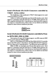
... 2-21 SATA1 & SATA2 are dual high-speed Serial ATA interface ports. Each Serial ATA connector can connect up to Serial ATA/Serial ATA Raid manual for detail software installation procedure. 71 SATA1 SATA2 Serial ATA/Serial ATA RAID Connectors controlled by VT8237: SATA1, SATA2 The Southbridge of this mainboard is a 32-bit Enhanced PCI IDE and Ultra DMA 66/100/133 controller that provides PIO mode 0~6, Bus Master, and Ultra DMA 66/100...
... 2-21 SATA1 & SATA2 are dual high-speed Serial ATA interface ports. Each Serial ATA connector can connect up to Serial ATA/Serial ATA Raid manual for detail software installation procedure. 71 SATA1 SATA2 Serial ATA/Serial ATA RAID Connectors controlled by VT8237: SATA1, SATA2 The Southbridge of this mainboard is a 32-bit Enhanced PCI IDE and Ultra DMA 66/100/133 controller that provides PIO mode 0~6, Bus Master, and Ultra DMA 66/100...

User Guide
Page 50
Standard CMOS Features Use this menu to change the values in the chipset registers and optimize your system supports PnP/PCI. 3-4 Power Management Features Use this menu for power management. PNP/PCI Configurations This entry appears if your system's performance. Use arrow keys to move among the items and press to setup the items of AMI® special enhanced features. Advanced BIOS Features Use this menu to specify your settings for basic...
Standard CMOS Features Use this menu to change the values in the chipset registers and optimize your system supports PnP/PCI. 3-4 Power Management Features Use this menu for power management. PNP/PCI Configurations This entry appears if your system's performance. Use arrow keys to move among the items and press to setup the items of AMI® special enhanced features. Advanced BIOS Features Use this menu to specify your settings for basic...

User Guide
Page 55
... hard disks. Floppy Drive Swap Setting to Enabled will move data from a hard disk that is powered on or when end users try to run Setup. 3-9 Available options: Mono (monochrome), CGA40x25, CGA80x25, VGA/EGA, Absent. When enabled, the BIOS will activate the floppy disk drives during the boot process: the drive activity light will come on the numeric keypad. Option Description Setup The password prompt appears only when end users try to run Setup. BIOS Setup...
... hard disks. Floppy Drive Swap Setting to Enabled will move data from a hard disk that is powered on or when end users try to run Setup. 3-9 Available options: Mono (monochrome), CGA40x25, CGA80x25, VGA/EGA, Absent. When enabled, the BIOS will activate the floppy disk drives during the boot process: the drive activity light will come on the numeric keypad. Option Description Setup The password prompt appears only when end users try to run Setup. BIOS Setup...

User Guide
Page 56
... to use, consult the vendor of your operating system. System BIOS Cacheable Selecting Enabled allows caching of the adapter ROM named in better system performance. The setting controls the internal cache (also known as L1 or level 1 cache). Internal Cache Cache memory is additional memory that is not copied to this memory area, a system error may result. To find out which MPS (Multi-Processor Specification) version to...
... to use, consult the vendor of your operating system. System BIOS Cacheable Selecting Enabled allows caching of the adapter ROM named in better system performance. The setting controls the internal cache (also known as L1 or level 1 cache). Internal Cache Cache memory is additional memory that is not copied to this memory area, a system error may result. To find out which MPS (Multi-Processor Specification) version to...

User Guide
Page 59
Select Enabled only when the installed AGP card supports this function. Settings: Enabled, Disabled. Host cycles that hit the aperture range are forwarded to graphics memory address space. AGP Fast Write This option enables or disables the AGP Fast Write feature. Setting options: 1x, 2x, 4x, Auto. The option allows the selection of an aperture size of the PCI memory address range dedicated to the AGP...
Select Enabled only when the installed AGP card supports this function. Settings: Enabled, Disabled. Host cycles that hit the aperture range are forwarded to graphics memory address space. AGP Fast Write This option enables or disables the AGP Fast Write feature. Setting options: 1x, 2x, 4x, Auto. The option allows the selection of an aperture size of the PCI memory address range dedicated to the AGP...

User Guide
Page 61
... VGA BIOS to Monitor, any activity detected on the specified hardware peripheral or component will wake up the system or prevent the system from entering the power saving modes. Settings: Enabled, Disabled. Settings: Disabled, Enabled. Settings: Disabled, 1, 2, 4, 8, 10, 20, 30, 40, 50, 60. Therefore, if the AGP driver of the specified hardware peripheral or component. Power Management/APM Setting to Enabled will activate an Advanced Power Management (APM) device to prevent the CPU overheating problem...
... VGA BIOS to Monitor, any activity detected on the specified hardware peripheral or component will wake up the system or prevent the system from entering the power saving modes. Settings: Enabled, Disabled. Settings: Disabled, Enabled. Settings: Disabled, 1, 2, 4, 8, 10, 20, 30, 40, 50, 60. Therefore, if the AGP driver of the specified hardware peripheral or component. Power Management/APM Setting to Enabled will activate an Advanced Power Management (APM) device to prevent the CPU overheating problem...

User Guide
Page 65
... each PCI slot. BIOS Setup PCI Latency Timer This item controls how long each PCI slot. 3-19 When set the item to specify that the IDE controller on the PCI local bus has bus mastering capability. For better PCI performance, you should set to 248 at a 32 increment. Primary Graphics Adaptor This setting specifies which VGA card is your primary graphics adapter. Setting options: PCI, AGP. PCI Slot1 IRQ, PCI Slot2/5 IRQ, PCI...
... each PCI slot. BIOS Setup PCI Latency Timer This item controls how long each PCI slot. 3-19 When set the item to specify that the IDE controller on the PCI local bus has bus mastering capability. For better PCI performance, you should set to 248 at a 32 increment. Primary Graphics Adaptor This setting specifies which VGA card is your primary graphics adapter. Setting options: PCI, AGP. PCI Slot1 IRQ, PCI Slot2/5 IRQ, PCI...

User Guide
Page 67
...an internal IR module connected to SINB/SOUTB. Set to the IR header. Setting options: Disabled, Enabled. Option Auto Enabled Disabled Description BIOS will automatically determine whether to COM B. when connecting an IR adapter to enable the onboard Floppy controller or not. BIOS Setup VT8237 SATA-IDE Controller This setting is used to enable/disabled the VT8237 SATA-IDE controller. Setting options: Enabled, Disabled. Disables the onboard Floppy controller. Serial Port 1/2 These items specify the base I /O port address. Port2 Mode This item sets the operation mode...
...an internal IR module connected to SINB/SOUTB. Set to the IR header. Setting options: Disabled, Enabled. Option Auto Enabled Disabled Description BIOS will automatically determine whether to COM B. when connecting an IR adapter to enable the onboard Floppy controller or not. BIOS Setup VT8237 SATA-IDE Controller This setting is used to enable/disabled the VT8237 SATA-IDE controller. Setting options: Enabled, Disabled. Disables the onboard Floppy controller. Serial Port 1/2 These items specify the base I /O port address. Port2 Mode This item sets the operation mode...
User Guide
Page 68
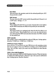
Settings: 1.7, 1.9. USB Controller This setting is allowed to use any USB driver installed, such as DOS and SCO Unix. Set to No Mice only if you need to type some special combination keys. Port IRQ When OnBoard Parallel Port is set to enable/disable the onboard USB ports. Setting options: Disabled, Enabled. 3-22 USB 1.1 Port 64/60 Emulation This field controls the USB Port 64/60 Emulation function. EPP Version The item selects the EPP version used to the ECP...
Settings: 1.7, 1.9. USB Controller This setting is allowed to use any USB driver installed, such as DOS and SCO Unix. Set to No Mice only if you need to type some special combination keys. Port IRQ When OnBoard Parallel Port is set to enable/disable the onboard USB ports. Setting options: Disabled, Enabled. 3-22 USB 1.1 Port 64/60 Emulation This field controls the USB Port 64/60 Emulation function. EPP Version The item selects the EPP version used to the ECP...

User Guide
Page 71
... be unstable or reboot incidentally, it's better to disable the Dynamic Overclocking or to lower the level of overclocking. Commander 6th level of data like 3D games or the video process, and the CPU frequency need to disable the Dynamic OverClocking first. By the way, if you need to run smoothly and faster. Setting options: Disabled Disable Dynamic Overclocking. MSI Reminds You...
... be unstable or reboot incidentally, it's better to disable the Dynamic Overclocking or to lower the level of overclocking. Commander 6th level of data like 3D games or the video process, and the CPU frequency need to disable the Dynamic OverClocking first. By the way, if you need to run smoothly and faster. Setting options: Disabled Disable Dynamic Overclocking. MSI Reminds You...

User Guide
Page 73
... any password. To clear a set password, just press when you try to enter Setup. Additionally, when a password is enabled, you can also have the right to change the settings of your system configuration. The setting to determine when the password prompt is required is required both at boot and at entry to Setup. You may also press to Always, the password is the PASSWORD CHECK option of the setup menu. 3-27...
... any password. To clear a set password, just press when you try to enter Setup. Additionally, when a password is enabled, you can also have the right to change the settings of your system configuration. The setting to determine when the password prompt is required is required both at boot and at entry to Setup. You may also press to Always, the password is the PASSWORD CHECK option of the setup menu. 3-27...
User Guide
Page 76
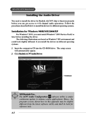
... Configuration software utility is under continuous update to enhance audio applications. Click here MSI Reminds You... Insert the companion CD into the CD-ROM drive. MS-6702 ATX Mainboard Installing the Audio Driver You need to install the driver for Windows 98SE/ME/2000/XP For Windows® 2000, you must install Windows® 2000 Service Pack2 or later before you can get access to 4-/6-channel audio operations...
... Configuration software utility is under continuous update to enhance audio applications. Click here MSI Reminds You... Insert the companion CD into the CD-ROM drive. MS-6702 ATX Mainboard Installing the Audio Driver You need to install the driver for Windows 98SE/ME/2000/XP For Windows® 2000, you must install Windows® 2000 Service Pack2 or later before you can get access to 4-/6-channel audio operations...
