User Manual
Page 1
Preface X99S SLI PLUS Motherboard G52-78851X3
Preface X99S SLI PLUS Motherboard G52-78851X3

User Manual
Page 11
Preface ▍▍Contents Chapter 1 Getting Started 1-1 Packing Contents 1-2 Assembly Precautions 1-3 Motherboard Specifications 1-4 Block Diagram 1-7 Connectors Quick Guide 1-8 Back Panel Quick Guide 1-10 CPU (Central Processing Unit 1-12 Introduction to the LGA2011-3 CPU 1-12 CPU & Heatsink Installation 1-...
Preface ▍▍Contents Chapter 1 Getting Started 1-1 Packing Contents 1-2 Assembly Precautions 1-3 Motherboard Specifications 1-4 Block Diagram 1-7 Connectors Quick Guide 1-8 Back Panel Quick Guide 1-10 CPU (Central Processing Unit 1-12 Introduction to the LGA2011-3 CPU 1-12 CPU & Heatsink Installation 1-...

User Manual
Page 12
... Booting Jumper 1-32 Switch 1-33 BIOS1: Multi-BIOS Switch 1-33 Drivers and Utilities 1-34 Driver/ Utilities Installation 1-34 Chapter 2 Quick Installation 2-1 CPU Installation 2-2 Memory Installation 2-4 Motherboard Installation 2-5 Power Connectors Installation 2-7 SATA HDD Installation 2-9 M.2 module Installation 2-10 Front Panel Connector Installation 2-11 JFP1 Connector Installation 2-11 Front Panel Audio Connector Installation 2-11...
... Booting Jumper 1-32 Switch 1-33 BIOS1: Multi-BIOS Switch 1-33 Drivers and Utilities 1-34 Driver/ Utilities Installation 1-34 Chapter 2 Quick Installation 2-1 CPU Installation 2-2 Memory Installation 2-4 Motherboard Installation 2-5 Power Connectors Installation 2-7 SATA HDD Installation 2-9 M.2 module Installation 2-10 Front Panel Connector Installation 2-11 JFP1 Connector Installation 2-11 Front Panel Audio Connector Installation 2-11...

User Manual
Page 15
The X99S SLI PLUS Series motherboards are based on Intel® X99 chipset for choosing the X99S SLI PLUS Series (MS-7885 v1.X) ATX motherboard. Designed to fit the advanced Intel® LGA2011-3 processor, the X99S SLI PLUS Series motherboards deliver a high performance and professional desktop platform solution. Chapter 1 Getting Started Thank you for optimal system efficiency.
The X99S SLI PLUS Series motherboards are based on Intel® X99 chipset for choosing the X99S SLI PLUS Series (MS-7885 v1.X) ATX motherboard. Designed to fit the advanced Intel® LGA2011-3 processor, the X99S SLI PLUS Series motherboards deliver a high performance and professional desktop platform solution. Chapter 1 Getting Started Thank you for optimal system efficiency.

User Manual
Page 16
Chapter 1 Getting Started 1-2 Packing Contents SATA9_10 SATA7_8 SATA3_4 SATA1_2 Motherboard Drivers & Utilities Disc Motherboard User Guide I/O Shield SATA Cable SLI Cable M-Connector * These pictures are for reference only and may vary without notice. * The packing contents may vary according to the model you purchased.
Chapter 1 Getting Started 1-2 Packing Contents SATA9_10 SATA7_8 SATA3_4 SATA1_2 Motherboard Drivers & Utilities Disc Motherboard User Guide I/O Shield SATA Cable SLI Cable M-Connector * These pictures are for reference only and may vary without notice. * The packing contents may vary according to the model you purchased.

User Manual
Page 17
.... Important A screwdriver (not included) may cause the computer to not recognize a component or fail to start. ■■Hold the motherboard by touching another metal object before installing or removing any installation step, please consult a certified computer technician. Assembly Precautions ■■The ...need help during any computer component. ■■Ensure that there are no loose screws or metal components on the motherboard or anywhere within the computer case. ■■Do not use the computer in this package are securely connected. Chapter 1 1-3...
.... Important A screwdriver (not included) may cause the computer to not recognize a component or fail to start. ■■Hold the motherboard by touching another metal object before installing or removing any installation step, please consult a certified computer technician. Assembly Precautions ■■The ...need help during any computer component. ■■Ensure that there are no loose screws or metal components on the motherboard or anywhere within the computer case. ■■Do not use the computer in this package are securely connected. Chapter 1 1-3...
User Manual
Page 18
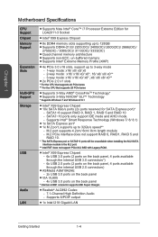
... Technology* ■■Supports 3-Way NVIDIA® SLI™ Technology * Supports Windows 7 and Windows 8/ 8.1 ■■Intel® X99 Express Chipset ■■10x SATA 6Gb/s ports ...Supports S/PDIF output ■■1x Intel I218 Gigabit LAN Getting Started 1-4 Chapter 1 Motherboard Specifications CPU Support Chipset Memory Support Expansion Slots Multi-GPU Support Storage USB Audio LAN ■... USB 3.0 ports on the back panel * Internal JUSB1 connector supports MSI Super Charger. ■■Realtek® ALC892 Codec -- 7.1-Channel High Definition Audio -- SATA7~10...
... Technology* ■■Supports 3-Way NVIDIA® SLI™ Technology * Supports Windows 7 and Windows 8/ 8.1 ■■Intel® X99 Express Chipset ■■10x SATA 6Gb/s ports ...Supports S/PDIF output ■■1x Intel I218 Gigabit LAN Getting Started 1-4 Chapter 1 Motherboard Specifications CPU Support Chipset Memory Support Expansion Slots Multi-GPU Support Storage USB Audio LAN ■... USB 3.0 ports on the back panel * Internal JUSB1 connector supports MSI Super Charger. ■■Realtek® ALC892 Codec -- 7.1-Channel High Definition Audio -- SATA7~10...

User Manual
Page 21
... 2.0 PCI Express Bus x1 x1 Intel I218 Gigabit LAN PCIe x1 slot PCI Express Bus 10 x SATA 6Gb/s (2 ports reserved for SATA Express) 6 x USB 3.0 6 x USB 2.0 X99 PCH x1 PCI Express Bus VIA VL805 4 x USB 3.0 LPC Bus x2 ASMEDIA ASM1042AE 2 x USB 3.0 (Gen2 x1) NV6792 Super I/O PS/2 Mouse / Keyboard Realtek ALC892 CS-Out...
... 2.0 PCI Express Bus x1 x1 Intel I218 Gigabit LAN PCIe x1 slot PCI Express Bus 10 x SATA 6Gb/s (2 ports reserved for SATA Express) 6 x USB 3.0 6 x USB 2.0 X99 PCH x1 PCI Express Bus VIA VL805 4 x USB 3.0 LPC Bus x2 ASMEDIA ASM1042AE 2 x USB 3.0 (Gen2 x1) NV6792 Super I/O PS/2 Mouse / Keyboard Realtek ALC892 CS-Out...
User Manual
Page 26
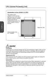
Overclocking This motherboard is not recommend. Be sure to apply an even layer of thermal paste (or thermal tape) between the CPU and the heatsink to ensure the ... the CPU from overheating. Any attempt to operate beyond product specifications. Always make sure that all other system components can seriously damage the CPU and motherboard. MSI does not guarantee the damages or risks caused by inadequate operation beyond product specifications is designed to support overclocking. Before attempting to overclock, please make...
Overclocking This motherboard is not recommend. Be sure to apply an even layer of thermal paste (or thermal tape) between the CPU and the heatsink to ensure the ... the CPU from overheating. Any attempt to operate beyond product specifications. Always make sure that all other system components can seriously damage the CPU and motherboard. MSI does not guarantee the damages or risks caused by inadequate operation beyond product specifications is designed to support overclocking. Before attempting to overclock, please make...
User Manual
Page 27
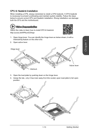
... below shown, it has risen away from the socket, open position. 1-13 Getting Started Open hinge lever. You can damage both the CPU and the motherboard. Open the load plate by pushing down on the other end. 2. Wrong installation can identify the hinge lever as below to full open load plate...
... below shown, it has risen away from the socket, open position. 1-13 Getting Started Open hinge lever. You can damage both the CPU and the motherboard. Open the load plate by pushing down on the other end. 2. Wrong installation can identify the hinge lever as below to full open load plate...

User Manual
Page 33
...up with your computer case. Align the mounting plate's mounting stands with the screw holes on the motherboard and secure the motherboard with the screws provided with the holes on the motherboard or within the computer case that may cause a short circuit of the computer case. Chapter 1 ...in your computer case. If there is prohibited. • Please make sure there are shown below. Mounting Screw Holes When installing the motherboard, first install the necessary mounting stands required for the mounting stands, is an I/O back plate that came with the computer case, ...
...up with your computer case. Align the mounting plate's mounting stands with the screw holes on the motherboard and secure the motherboard with the screws provided with the holes on the motherboard or within the computer case that may cause a short circuit of the computer case. Chapter 1 ...in your computer case. If there is prohibited. • Please make sure there are shown below. Mounting Screw Holes When installing the motherboard, first install the necessary mounting stands required for the mounting stands, is an I/O back plate that came with the computer case, ...

User Manual
Page 34
Getting Started 1-20 If done correctly, the clip on the motherboard's power connector. 1.G2.rG3o.urG4on.urdGonurdonudnd JPWR2 5.+61.+721.V+821.V+21V2V SATA9_10 SATA7_8 SATA3_4 SATA1_2 1.+23.+3.33.G4V.3.r+5Vo.5uG6Vn.r7+do.5uG8Vn.rP9do.Wu51nV0R1d.....5+4V5.GVrJoPunWd R1 Important Make sure that all the power cables are securely connected to a proper ATX power supply to ensure stable operation of the motherboard. Chapter 1 Power Supply Video Demonstration Watch the video to learn how to connect an ATX power supply. http://youtu.be hooked on the power cable...
Getting Started 1-20 If done correctly, the clip on the motherboard's power connector. 1.G2.rG3o.urG4on.urdGonurdonudnd JPWR2 5.+61.+721.V+821.V+21V2V SATA9_10 SATA7_8 SATA3_4 SATA1_2 1.+23.+3.33.G4V.3.r+5Vo.5uG6Vn.r7+do.5uG8Vn.rP9do.Wu51nV0R1d.....5+4V5.GVrJoPunWd R1 Important Make sure that all the power cables are securely connected to a proper ATX power supply to ensure stable operation of the motherboard. Chapter 1 Power Supply Video Demonstration Watch the video to learn how to connect an ATX power supply. http://youtu.be hooked on the power cable...

User Manual
Page 35
... installing the M.2 PCIe interface module, please set the "M.2 PCH Strap" for any necessary additional hardware or software changes. 1-21 Getting Started Chapter 1 Expansion Slots This motherboard contains numerous slots for expansion cards, such as discrete graphics or audio cards. PCI_E1~6: PCIe Expansion Slots The PCIe slot supports the PCIe interface expansion...
... installing the M.2 PCIe interface module, please set the "M.2 PCH Strap" for any necessary additional hardware or software changes. 1-21 Getting Started Chapter 1 Expansion Slots This motherboard contains numerous slots for expansion cards, such as discrete graphics or audio cards. PCI_E1~6: PCIe Expansion Slots The PCIe slot supports the PCIe interface expansion...

User Manual
Page 36
...will significantly boost the system's graphics performance. Locate the expansion slot(s) on the motherboard. For a single video card installation, using the PCI_E1 slot is recommended. 3. ...card into its expansion slot(s). Getting Started 1-22 If needed, screw the edge of the motherboard's expansion slots. Some video cards might require a power cable directly from the computer case....learn how to the computer case. Chapter 1 Video/ Graphics Cards If available, this motherboard takes advantage of the CPU's integrate graphics processor, but discrete video cards can be ...
...will significantly boost the system's graphics performance. Locate the expansion slot(s) on the motherboard. For a single video card installation, using the PCI_E1 slot is recommended. 3. ...card into its expansion slot(s). Getting Started 1-22 If needed, screw the edge of the motherboard's expansion slots. Some video cards might require a power cable directly from the computer case....learn how to the computer case. Chapter 1 Video/ Graphics Cards If available, this motherboard takes advantage of the CPU's integrate graphics processor, but discrete video cards can be ...

User Manual
Page 37
Video Demonstration Watch the video to learn how to one SATA device. Refer to the motherboard for further installation instructions. • Please do not fold the SATA cable at a 90-degree angle. http://youtu.be unavailable when installing a M.2 SATA interface module ...
Video Demonstration Watch the video to learn how to one SATA device. Refer to the motherboard for further installation instructions. • Please do not fold the SATA cable at a 90-degree angle. http://youtu.be unavailable when installing a M.2 SATA interface module ...

User Manual
Page 39
... connectors support Smart Fan Control with +12V. Some system fans may not connect to the motherboard and will instead connect to take advantage of the CPU fan control. If the motherboard has a System Hardware Monitor chipset on the motherboard to connect all system fans. SATA9_10 SATA7_8 SATA3_4 SATA1_2 Chapter 1 CPUFAN1~2,SYSFAN1~3: Fan Power...
... connectors support Smart Fan Control with +12V. Some system fans may not connect to the motherboard and will instead connect to take advantage of the CPU fan control. If the motherboard has a System Hardware Monitor chipset on the motherboard to connect all system fans. SATA9_10 SATA7_8 SATA3_4 SATA1_2 Chapter 1 CPUFAN1~2,SYSFAN1~3: Fan Power...

User Manual
Page 40
... MConnectors to simplify installation. Video Demonstration Watch the video to learn how to the front panel switches and LEDs. http://youtu.be plugged into the motherboard. Chapter 1 JFP1, JFP2: System Panel Connectors These connectors connect to Install front panel connectors. Plug all the wires from the case, pins marked by small...
... MConnectors to simplify installation. Video Demonstration Watch the video to learn how to the front panel switches and LEDs. http://youtu.be plugged into the motherboard. Chapter 1 JFP1, JFP2: System Panel Connectors These connectors connect to Install front panel connectors. Plug all the wires from the case, pins marked by small...

User Manual
Page 41
...application is in S3, S4, S5 state. • We recommend that the VCC and GND pins must connect the device to check if your motherboard has Super-Charger technology. • For iPad, JUSB1 (red mark) can still charge iPad in stand-by or hibernation mode (S3/ S4/... Super-Charger technology which provides quicker USB charging of your computer. To enable this feature, please install the MSI Super-Charger application on select MSI motherboard models. Please note that when the Super-Charger application is only available on your smartphone or other USB-powered devices. Important &#...
...application is in S3, S4, S5 state. • We recommend that the VCC and GND pins must connect the device to check if your motherboard has Super-Charger technology. • For iPad, JUSB1 (red mark) can still charge iPad in stand-by or hibernation mode (S3/ S4/... Super-Charger technology which provides quicker USB charging of your computer. To enable this feature, please install the MSI Super-Charger application on select MSI motherboard models. Please note that when the Super-Charger application is only available on your smartphone or other USB-powered devices. Important &#...
User Manual
Page 44
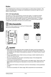
...Genie function. • We do not guarantee the OC Genie overclocking range or the damages/risks caused by MSI. • To ensure successfully OC Genie usage, MSI components are recommended. You can specify how OC Genie to be enabled by using the "OC Genie Function Control...manual for optimal performance. This section will be /nIpRvWkUazg Chapter 1 OGCENIE OGCENIE SATA9_10 SATA7_8 SATA3_4 SATA1_2 On Off Important • This motherboard provides two ways to enable OC Genie: press the physical OC Genie button on how to control various functions. http://youtu.be automatically...
...Genie function. • We do not guarantee the OC Genie overclocking range or the damages/risks caused by MSI. • To ensure successfully OC Genie usage, MSI components are recommended. You can specify how OC Genie to be enabled by using the "OC Genie Function Control...manual for optimal performance. This section will be /nIpRvWkUazg Chapter 1 OGCENIE OGCENIE SATA9_10 SATA7_8 SATA3_4 SATA1_2 On Off Important • This motherboard provides two ways to enable OC Genie: press the physical OC Genie button on how to control various functions. http://youtu.be automatically...

User Manual
Page 46
... • Users will be unbootable. Do not clear the CMOS RAM while the system is on . The overclocking results will damage the motherboard. If you want to clear the system configuration, set this jumper to boot at their own risks. Chapter 1 Keep Data Clear Data SATA9_10... the system will try extreme low temperature overclocking at a stable processor frequency and to prevent the system from a battery located on the motherboard to clear the CMOS RAM. Jumper JBAT1: Clear CMOS Jumper There is CMOS RAM onboard that provides the extreme overclocking conditions, to "Enabled...
... • Users will be unbootable. Do not clear the CMOS RAM while the system is on . The overclocking results will damage the motherboard. If you want to clear the system configuration, set this jumper to boot at their own risks. Chapter 1 Keep Data Clear Data SATA9_10... the system will try extreme low temperature overclocking at a stable processor frequency and to prevent the system from a battery located on the motherboard to clear the CMOS RAM. Jumper JBAT1: Clear CMOS Jumper There is CMOS RAM onboard that provides the extreme overclocking conditions, to "Enabled...


