User Manual
Page 3
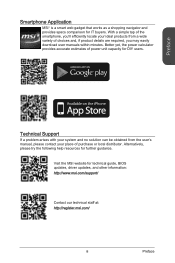
..., you 'll efficiently locate your ideal products from the user's manual, please contact your place of the smartphone, you may easily download user manuals within minutes. Visit the MSI website for IT buyers. Smartphone Application MSI+ is a smart web gadget that works as a shopping navigator and provides specs comparison for technical guide, BIOS updates, driver updates, and other information: http://www.msi.com/support/ Contact our technical staff...
..., you 'll efficiently locate your ideal products from the user's manual, please contact your place of the smartphone, you may easily download user manuals within minutes. Visit the MSI website for IT buyers. Smartphone Application MSI+ is a smart web gadget that works as a shopping navigator and provides specs comparison for technical guide, BIOS updates, driver updates, and other information: http://www.msi.com/support/ Contact our technical staff...

User Manual
Page 11
...-3 CPU 1-12 CPU & Heatsink Installation 1-13 Memory 1-16 Up to Quad-Channel mode 1-16 Defined Channel list 1-16 Suggestions for Multi-Channel mode population rule 1-17 Dual-Channel mode 1-17 Triple-Channel mode 1-17 Quad-Channel mode 1-17 Quad-Channel mode 1-18 Mounting Screw Holes 1-19 Power Supply 1-20 JPWR1~2: ATX Power Connectors 1-20 Expansion Slots 1-21 PCI_E1~6: PCIe Expansion Slots 1-21 PCIe Bandwidth Table 1-21 Video/ Graphics Cards 1-22 Single Video Card Installation 1-22 Internal Connectors 1-23 SATA1~10: SATA Connectors 1-23 SATA_EX1: SATA Express Connector...
...-3 CPU 1-12 CPU & Heatsink Installation 1-13 Memory 1-16 Up to Quad-Channel mode 1-16 Defined Channel list 1-16 Suggestions for Multi-Channel mode population rule 1-17 Dual-Channel mode 1-17 Triple-Channel mode 1-17 Quad-Channel mode 1-17 Quad-Channel mode 1-18 Mounting Screw Holes 1-19 Power Supply 1-20 JPWR1~2: ATX Power Connectors 1-20 Expansion Slots 1-21 PCI_E1~6: PCIe Expansion Slots 1-21 PCIe Bandwidth Table 1-21 Video/ Graphics Cards 1-22 Single Video Card Installation 1-22 Internal Connectors 1-23 SATA1~10: SATA Connectors 1-23 SATA_EX1: SATA Express Connector...
User Manual
Page 18
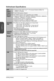
... 1 Motherboard Specifications CPU Support Chipset Memory Support Expansion Slots Multi-GPU Support Storage USB Audio LAN ■■Supports New Intel® Core™ i7 Processor Extreme Edition for SATA Express port)* -- M.2 port supports 4.2cm/ 6cm/ 8cm length module -- M.2 PCIe interface does not support RAID 0, RAID1, RAID 5 and RAID 10. * The SATA Express port or SATA5~6 ports will be unavailable when installing the M.2 SATA interface module in the M.2 port. ** Intel RST does not support PCIe M.2 SSD with Legacy ROM. ■■Intel® X99 Express Chipset -- 6x USB...
... 1 Motherboard Specifications CPU Support Chipset Memory Support Expansion Slots Multi-GPU Support Storage USB Audio LAN ■■Supports New Intel® Core™ i7 Processor Extreme Edition for SATA Express port)* -- M.2 port supports 4.2cm/ 6cm/ 8cm length module -- M.2 PCIe interface does not support RAID 0, RAID1, RAID 5 and RAID 10. * The SATA Express port or SATA5~6 ports will be unavailable when installing the M.2 SATA interface module in the M.2 port. ** Intel RST does not support PCIe M.2 SSD with Legacy ROM. ■■Intel® X99 Express Chipset -- 6x USB...

User Manual
Page 34
...+2ds2n5.+3dV2.5+4V5.GVrJoPunWd R1 Important Make sure that all the power cables are securely connected to a proper ATX power supply to ensure stable operation of the motherboard. Getting Started 1-20 To connect the ATX power supply, align the power supply cable with the connector and firmly press the cable into the connector. If done correctly, the clip on the power cable should be /gkDYyR_83I4 JPWR1~2: ATX Power Connectors These connectors allow you to install power supply connectors.
...+2ds2n5.+3dV2.5+4V5.GVrJoPunWd R1 Important Make sure that all the power cables are securely connected to a proper ATX power supply to ensure stable operation of the motherboard. Getting Started 1-20 To connect the ATX power supply, align the power supply cable with the connector and firmly press the cable into the connector. If done correctly, the clip on the power cable should be /gkDYyR_83I4 JPWR1~2: ATX Power Connectors These connectors allow you to install power supply connectors.

User Manual
Page 37
... connector is recommended that the flat connector be connected to the manual that large SATA devices, such as HDDs, SSDs, and optical drives, be screwed down into the case. Important • The SATA5 and SATA6 ports will be /RZsMpqxythc SATA5 SATA6 SATA2 SATA4 SATA1 SATA8 SATA3 SATA10 SATA7 SATA9 ■■SATA1~6 support RAID 0, RAID 1, RAID 5 and RAID 10. ■■SATA7~10 ports only support IDE mode and AHCI mode...
... connector is recommended that the flat connector be connected to the manual that large SATA devices, such as HDDs, SSDs, and optical drives, be screwed down into the case. Important • The SATA5 and SATA6 ports will be /RZsMpqxythc SATA5 SATA6 SATA2 SATA4 SATA1 SATA8 SATA3 SATA10 SATA7 SATA9 ■■SATA1~6 support RAID 0, RAID 1, RAID 5 and RAID 10. ■■SATA7~10 ports only support IDE mode and AHCI mode...

User Manual
Page 38
... -1 connector by a SATA Express cable. SATA9_10 SATA7_8 SATA3_4 SATA1_2 Chapter 1 M2_1: M.2 Port The M.2 port supports either M.2 SATA 6Gb/s module or M.2 PCIe module. Getting Started 1-24 SATA_EX1: SATA Express Connector The SATA Express, a new high performance storage interface, supports to connect 1 SATA Express device with Legacy ROM. • M.2 PCIe interface does not support RAID 0, RAID1, RAID 5 and RAID 10. • Always turn off the power supply and unplug the power cord from the power outlet before installing or removing the M.2 module. Connects the SATA Express device...
... -1 connector by a SATA Express cable. SATA9_10 SATA7_8 SATA3_4 SATA1_2 Chapter 1 M2_1: M.2 Port The M.2 port supports either M.2 SATA 6Gb/s module or M.2 PCIe module. Getting Started 1-24 SATA_EX1: SATA Express Connector The SATA Express, a new high performance storage interface, supports to connect 1 SATA Express device with Legacy ROM. • M.2 PCIe interface does not support RAID 0, RAID1, RAID 5 and RAID 10. • Always turn off the power supply and unplug the power cord from the power outlet before installing or removing the M.2 module. Connects the SATA Express device...
User Manual
Page 44
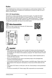
.... To disable OC Genie, Set this button to ON while the system is at the user's own risk. Please refer to the BIOS section of the manual for optimal performance. This section will be automatically overclock for instructions on how to change your motherboard's functions through the use the OC Genie button. On the next boot, the processor will explain how to turn off mode. Video Demonstration...
.... To disable OC Genie, Set this button to ON while the system is at the user's own risk. Please refer to the BIOS section of the manual for optimal performance. This section will be automatically overclock for instructions on how to change your motherboard's functions through the use the OC Genie button. On the next boot, the processor will explain how to turn off mode. Video Demonstration...

User Manual
Page 71
...Timer [32] Sets latency timer of PCI interface device. [Options: 32, 64, 96, 128, 160, 192, 224, 248 PCI Bus clocks] ▶▶ACPI Settings Sets ACPI parameters of the onboard Power LED. [Dual Color] The power LED turns to another color to indicate the S3 state. [Blinking] The power LED blinks to enter the sub-menu. ▶▶Onboard LAN Controller [Enabled] Enables or disables the onboard LAN controller. ▶▶LAN Option ROM [Disabled] Enables or disables the legacy network Boot Option ROM for SATA storage devices. AHCI (Advanced Host Controller Interface) offers...
...Timer [32] Sets latency timer of PCI interface device. [Options: 32, 64, 96, 128, 160, 192, 224, 248 PCI Bus clocks] ▶▶ACPI Settings Sets ACPI parameters of the onboard Power LED. [Dual Color] The power LED turns to another color to indicate the S3 state. [Blinking] The power LED blinks to enter the sub-menu. ▶▶Onboard LAN Controller [Enabled] Enables or disables the onboard LAN controller. ▶▶LAN Option ROM [Disabled] Enables or disables the legacy network Boot Option ROM for SATA storage devices. AHCI (Advanced Host Controller Interface) offers...

User Manual
Page 72
... 3 BIOS Setup 3-10 ▶▶sSATA Mode [AHCI Mode] (For SATA7~10) Sets the operation mode of the onboard 2nd SATA controller. [IDE Mode] Specify the IDE mode for SATA storage devices. [AHCI Mode] Specify the AHCI mode for UEFI applications. ▶▶Power Management Setup Sets system Power Management of SATA storage device, such as Native Command Queuing (NCQ) and hot-plugging. ▶▶SATAX Hot Plug [Disabled] Allows user to enter the sub-menu. Press to enter the submenu. ▶▶USB Controller [Enabled] Enables or disables all USB controller. ▶...
... 3 BIOS Setup 3-10 ▶▶sSATA Mode [AHCI Mode] (For SATA7~10) Sets the operation mode of the onboard 2nd SATA controller. [IDE Mode] Specify the IDE mode for SATA storage devices. [AHCI Mode] Specify the AHCI mode for UEFI applications. ▶▶Power Management Setup Sets system Power Management of SATA storage device, such as Native Command Queuing (NCQ) and hot-plugging. ▶▶SATAX Hot Plug [Disabled] Allows user to enter the sub-menu. Press to enter the submenu. ▶▶USB Controller [Enabled] Enables or disables all USB controller. ▶...

User Manual
Page 73
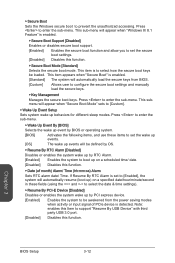
... Windows 8/ 8.1 or disables for Windows 8/ 8.1] Enables or disables the Windows 8/ 8.1 fast boot feature. Chapter 3 3-11 BIOS Setup It will switch to UEFI mode to meet the Windows 8/ 8.1 requirement. [Disabled] Disables this function. ▶▶MSI Fast Boot [Disabled] MSI Fast Boot is faster than the boot time of "Fast Boot". [Enabled] Enables the MSI Fast Boot function to speed up booting time. And the following "Fast Boot" will not support S4 & S5 wake up by USB and PCIe devices. ▶▶Restore after AC Power...
... Windows 8/ 8.1 or disables for Windows 8/ 8.1] Enables or disables the Windows 8/ 8.1 fast boot feature. Chapter 3 3-11 BIOS Setup It will switch to UEFI mode to meet the Windows 8/ 8.1 requirement. [Disabled] Disables this function. ▶▶MSI Fast Boot [Disabled] MSI Fast Boot is faster than the boot time of "Fast Boot". [Enabled] Enables the MSI Fast Boot function to speed up booting time. And the following "Fast Boot" will not support S4 & S5 wake up by USB and PCIe devices. ▶▶Restore after AC Power...
User Manual
Page 74
... to enter the sub-menu. ▶▶Wake Up Event By [BIOS] Selects the wake up event by PCI express device. [Enabled] Enables the system to select the date & time settings). ▶▶Resume By PCI-E Device [Disabled] Disables or enables the system wake up behaviors for different sleep modes. This sub-menu will appear when "Windows 8/ 8.1 Feature" is detected. Chapter 3 BIOS Setup 3-12 This item is to select how the secure boot keys be...
... to enter the sub-menu. ▶▶Wake Up Event By [BIOS] Selects the wake up event by PCI express device. [Enabled] Enables the system to select the date & time settings). ▶▶Resume By PCI-E Device [Disabled] Disables or enables the system wake up behaviors for different sleep modes. This sub-menu will appear when "Windows 8/ 8.1 Feature" is detected. Chapter 3 BIOS Setup 3-12 This item is to select how the secure boot keys be...

User Manual
Page 76
... installed boot devices. You may also press to [Enabled] later. [Options: Disabled, Enabled, Reset] Chapter 3 BIOS Setup 3-14 user has full rights to change the BIOS items. Important When selecting the Administrator / User Password items, a password box will return to abort the selection. To clear the warning message, set password from legacy or UEFI architecture depending on the screen. Type the password then press . Once the password is being disabled. ▶▶Boot Mode Select [LEGACY+UEFI] Sets the system boot mode from CMOS memory...
... installed boot devices. You may also press to [Enabled] later. [Options: Disabled, Enabled, Reset] Chapter 3 BIOS Setup 3-14 user has full rights to change the BIOS items. Important When selecting the Administrator / User Password items, a password box will return to abort the selection. To clear the warning message, set password from legacy or UEFI architecture depending on the screen. Type the password then press . Once the password is being disabled. ▶▶Boot Mode Select [LEGACY+UEFI] Sets the system boot mode from CMOS memory...

User Manual
Page 77
... all changes and restore to the previous values. ▶▶Restore Defaults This item is used to restore/ load all default values by the BIOS vendor. ▶▶Boot Override The installed boot-able devices will appear on this menu, you can select one of them be a boot device to start booting. Chapter 3 3-15 BIOS Setup Save & Exit ▶▶Discard Changes and Exit Exit BIOS setup without saving any change.
... all changes and restore to the previous values. ▶▶Restore Defaults This item is used to restore/ load all default values by the BIOS vendor. ▶▶Boot Override The installed boot-able devices will appear on this menu, you can select one of them be a boot device to start booting. Chapter 3 3-15 BIOS Setup Save & Exit ▶▶Discard Changes and Exit Exit BIOS setup without saving any change.
User Manual
Page 79
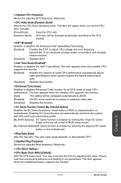
...;▶Ring Ratio [Auto] Sets the ring ratio. You may overclock the CPU by virtual button in BIOS or physical button on motherboard. This item appears when the installed CPU supports this function. [Enabled] Enables this function to adjust CPU voltage and core frequency dynamically. Please note that overclocking behavior and stability is enabled by clicking the virtual OC Genie button at the top left corner of BIOS setup screen. [By Onboard Button]OC Genie function is...
...;▶Ring Ratio [Auto] Sets the ring ratio. You may overclock the CPU by virtual button in BIOS or physical button on motherboard. This item appears when the installed CPU supports this function. [Enabled] Enables this function to adjust CPU voltage and core frequency dynamically. Please note that overclocking behavior and stability is enabled by clicking the virtual OC Genie button at the top left corner of BIOS setup screen. [By Onboard Button]OC Genie function is...
User Manual
Page 80
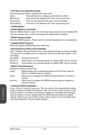
...you install the memory modules that supports this function. [Profile 1] Uses profile1 over-clocking settings of installed XMP memory module. [Profile 2] Uses profile2 over-clocking settings of installed memory modules. [Link] Allows user to configure the DRAM timing manually for all memory channel. [UnLink] Allows user to configure the DRAM timing manually for respective memory channel. ▶▶Advanced DRAM Configuration Press to load the default settings.) Chapter 3 BIOS Setup 3-18 This item appears when a CPU that support X.M.P. Please note the overclocking behavior...
...you install the memory modules that supports this function. [Profile 1] Uses profile1 over-clocking settings of installed XMP memory module. [Profile 2] Uses profile2 over-clocking settings of installed memory modules. [Link] Allows user to configure the DRAM timing manually for all memory channel. [UnLink] Allows user to configure the DRAM timing manually for respective memory channel. ▶▶Advanced DRAM Configuration Press to load the default settings.) Chapter 3 BIOS Setup 3-18 This item appears when a CPU that support X.M.P. Please note the overclocking behavior...
User Manual
Page 84
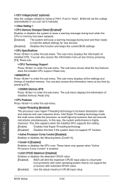
.... [Enabled] BIOS will set the voltage automatically or you can execute instructions simultaneously. The sub-menu shows what the key features does the installed CPU support. Read only. ▶▶CPU Features Press to enter the sub-menu. ▶▶Hyper-Threading [Enabled] The processor uses Hyper-Threading technology to enter the sub-menu. These items only appear when "Active Processor Cores Control" is highly improved. Read only. ▶▶MEMORY-Z Press to memory/ PCH...
.... [Enabled] BIOS will set the voltage automatically or you can execute instructions simultaneously. The sub-menu shows what the key features does the installed CPU support. Read only. ▶▶CPU Features Press to enter the sub-menu. ▶▶Hyper-Threading [Enabled] The processor uses Hyper-Threading technology to enter the sub-menu. These items only appear when "Active Processor Cores Control" is highly improved. Read only. ▶▶MEMORY-Z Press to memory/ PCH...

User Manual
Page 86
... to adjust CPU voltage and core frequency dynamically. It can decrease average power consumption and average heat production. [Disabled] Disables EIST. ▶▶Intel Turbo Boost [Enabled] Enables or disables the Intel® Turbo Boost. ▶▶Intel C-State [Enabled] C-state is a processor power management technology defined by ACPI. [Auto] This setting will be configured automatically by BIOS. [Enabled] Detects the idle state of CPU package in Turbo Boost mode. This item...
... to adjust CPU voltage and core frequency dynamically. It can decrease average power consumption and average heat production. [Disabled] Disables EIST. ▶▶Intel Turbo Boost [Enabled] Enables or disables the Intel® Turbo Boost. ▶▶Intel C-State [Enabled] C-state is a processor power management technology defined by ACPI. [Auto] This setting will be configured automatically by BIOS. [Enabled] Detects the idle state of CPU package in Turbo Boost mode. This item...

User Manual
Page 88
... BIOS file inside USB flash disk (FAT/ FAT32 format only). ▶▶BIOS Boot Function [Disabled] Enables or disables the system to boot form USB flash disk with BIOS file. [Enabled] Enables the system to boot from the BIOS within USB flash disk. [Disabled] Enables the system to boot from the BIOS within ROM on motherboard. *This may cause system unstable, MSI recommend it only for power users. ▶▶Select one file to update BIOS and ME Selects a BIOS file, includes the ME management settings, in the USB flash disk...
... BIOS file inside USB flash disk (FAT/ FAT32 format only). ▶▶BIOS Boot Function [Disabled] Enables or disables the system to boot form USB flash disk with BIOS file. [Enabled] Enables the system to boot from the BIOS within USB flash disk. [Disabled] Enables the system to boot from the BIOS within ROM on motherboard. *This may cause system unstable, MSI recommend it only for power users. ▶▶Select one file to update BIOS and ME Selects a BIOS file, includes the ME management settings, in the USB flash disk...

User Manual
Page 97
... and Resetting RAID Volumes: The Serial ATA RAID volume may be different from your OS. Important The "Device Model", "Serial #" and "Size" in the following example might be configured using the RAID Configuration utility stored within the Intel RAID Option ROM. After the above message shows, press and keys simultaneously to enter Configuration Utility.. During the Power-On Self Test (POST), the following procedure is the Intel RAID implementation and provides BIOS and DOS disk services...
... and Resetting RAID Volumes: The Serial ATA RAID volume may be different from your OS. Important The "Device Model", "Serial #" and "Size" in the following example might be configured using the RAID Configuration utility stored within the Intel RAID Option ROM. After the above message shows, press and keys simultaneously to enter Configuration Utility.. During the Power-On Self Test (POST), the following procedure is the Intel RAID implementation and provides BIOS and DOS disk services...

User Manual
Page 106
... with RAID mode. Set the SATA Mode to accelerate the system performance. Powered off. 7. Important Check your SSD manufacturer's website, upgrade firmware in BIOS. Follow these steps to support Intel® Rapid Storage Technology. Install Intel RAID driver Appendix B 6. Intel RAID B-12 Even though there is only one hard drive, you must be installed in the RAID ready disk in BIOS. 3. Install Windows operating system. 4. Connect the SSD. 8. Insert the MSI Driver DVD into the DVD-ROM drive. 5. Intel® Rapid Storage Technology...
... with RAID mode. Set the SATA Mode to accelerate the system performance. Powered off. 7. Important Check your SSD manufacturer's website, upgrade firmware in BIOS. Follow these steps to support Intel® Rapid Storage Technology. Install Intel RAID driver Appendix B 6. Intel RAID B-12 Even though there is only one hard drive, you must be installed in the RAID ready disk in BIOS. 3. Install Windows operating system. 4. Connect the SSD. 8. Insert the MSI Driver DVD into the DVD-ROM drive. 5. Intel® Rapid Storage Technology...


