User Manual
Page 13
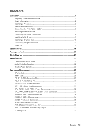
...Information 2 Installing a Processor 3 Installing DDR4 memory 5 Connecting the Front Panel Header 6 Installing the Motherboard 7 Connecting the Power Connectors 8 Installing SATA Drives 9 Installing a Graphics Card 10 Connecting Peripheral Devices 11 Power On...12 Specifications...15 Package contents 20 Block Diagram ...21 Rear I/O Panel ...22 LAN Port LED Status Table 22 Audio Ports Configuration 22 Realtek Audio Console 23 Overview of Components 25 CPU Socket ...27 DIMM Slots...28 PCI_E1~5: PCIe Expansion Slots 29 M2_1~2: M.2 Slots (Key M 30 SATA1~6: SATA 6Gb/s Connectors 31...
...Information 2 Installing a Processor 3 Installing DDR4 memory 5 Connecting the Front Panel Header 6 Installing the Motherboard 7 Connecting the Power Connectors 8 Installing SATA Drives 9 Installing a Graphics Card 10 Connecting Peripheral Devices 11 Power On...12 Specifications...15 Package contents 20 Block Diagram ...21 Rear I/O Panel ...22 LAN Port LED Status Table 22 Audio Ports Configuration 22 Realtek Audio Console 23 Overview of Components 25 CPU Socket ...27 DIMM Slots...28 PCI_E1~5: PCIe Expansion Slots 29 M2_1~2: M.2 Slots (Key M 30 SATA1~6: SATA 6Gb/s Connectors 31...

User Manual
Page 14
... RGB LED connectors 39 Installing OS, Drivers & Utilities 40 Installing Windows® 10 40 Installing Drivers 40 Installing Utilities 40 BIOS Setup ...41 Entering BIOS Setup 41 Resetting BIOS...42 Updating BIOS...42 EZ Mode ...44 Advanced Mode ...46 SETTINGS...47 Advanced...47 Boot...52 Security ...53 Save & Exit...54 OC...55 M-FLASH ...59 OC PROFILE ...60 HARDWARE MONITOR 61 A-XMP Operation 62 AMD RAID Configuration 63 Enabling RAIDXpert2 Configuration Utility 63 Initializing Disks 64 Creating Arrays...65 Deleting Arrays ...66 Installing RAID Driver 67 Troubleshooting 68...
... RGB LED connectors 39 Installing OS, Drivers & Utilities 40 Installing Windows® 10 40 Installing Drivers 40 Installing Utilities 40 BIOS Setup ...41 Entering BIOS Setup 41 Resetting BIOS...42 Updating BIOS...42 EZ Mode ...44 Advanced Mode ...46 SETTINGS...47 Advanced...47 Boot...52 Security ...53 Save & Exit...54 OC...55 M-FLASH ...59 OC PROFILE ...60 HARDWARE MONITOR 61 A-XMP Operation 62 AMD RAID Configuration 63 Enabling RAIDXpert2 Configuration Utility 63 Initializing Disks 64 Creating Arrays...65 Deleting Arrays ...66 Installing RAID Driver 67 Troubleshooting 68...

User Manual
Page 15
... PCIe 3.0 x1 slots* * PCI_E2 will be unavailable when installing the PCIe card in PCI_E4 slot. ** The speeds may vary for more information on next page Specifications 15 Specifications CPU Chipset Memory Expansion Slot Onboard Graphics Multi-GPU LAN Supports 2nd and 3rd Gen AMD Ryzen™ / Ryzen™ with Radeon™ Vega Graphics and 2nd Gen AMD Ryzen™ with Radeon™ Graphics Desktop Processors for Socket AM4 AMD® X570 Chipset y 4x DDR4 memory slots, support...
... PCIe 3.0 x1 slots* * PCI_E2 will be unavailable when installing the PCIe card in PCI_E4 slot. ** The speeds may vary for more information on next page Specifications 15 Specifications CPU Chipset Memory Expansion Slot Onboard Graphics Multi-GPU LAN Supports 2nd and 3rd Gen AMD Ryzen™ / Ryzen™ with Radeon™ Vega Graphics and 2nd Gen AMD Ryzen™ with Radeon™ Graphics Desktop Processors for Socket AM4 AMD® X570 Chipset y 4x DDR4 memory slots, support...
User Manual
Page 37
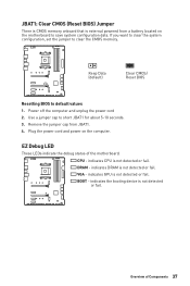
... motherboard. EZ Debug LED These LEDs indicate the debug status of Components 37 If you want to clear the system configuration, set the jumper to default values 1. Power off the computer and unplug the power cord 2. Keep Data (default) Clear CMOS/ Reset BIOS Resetting BIOS to clear the CMOS memory. CPU - Plug the power cord and power on the motherboard to short JBAT1 for about 5-10 seconds. 3. indicates CPU is not detected or fail. BOOT - Remove the jumper cap from a battery located...
... motherboard. EZ Debug LED These LEDs indicate the debug status of Components 37 If you want to clear the system configuration, set the jumper to default values 1. Power off the computer and unplug the power cord 2. Keep Data (default) Clear CMOS/ Reset BIOS Resetting BIOS to clear the CMOS memory. CPU - Plug the power cord and power on the motherboard to short JBAT1 for about 5-10 seconds. 3. indicates CPU is not detected or fail. BOOT - Remove the jumper cap from a battery located...

User Manual
Page 39
... power outlet before installing or removing the RGB LED strip. y Please use MSI's software to the LED strip. Important y The JRAINBOW connector supports up to 200 LEDs. Overview of Components 39 In the case of 20% brightness, the connector supports up to connect the WS2812B Individually Addressable RGB LED strips 5V. 1 1 +5V 2 3 No Pin 4 Data Ground Addressable RGB LED Strip Connection 1 +5V D JRAINBOW connector Rainbow RGB LED extension cable (optional) Addressable RGB LED Fan Connection JRAINBOW connector...
... power outlet before installing or removing the RGB LED strip. y Please use MSI's software to the LED strip. Important y The JRAINBOW connector supports up to 200 LEDs. Overview of Components 39 In the case of 20% brightness, the connector supports up to connect the WS2812B Individually Addressable RGB LED strips 5V. 1 1 +5V 2 3 No Pin 4 Data Ground Addressable RGB LED Strip Connection 1 +5V D JRAINBOW connector Rainbow RGB LED extension cable (optional) Addressable RGB LED Fan Connection JRAINBOW connector...

User Manual
Page 40
... above. 2. Power on the computer case. 4. If you turn off the AutoPlay feature from the Windows Control Panel, you can still manually execute the DVDSetup.exe from the Boot Menu. 6. Click OK button to open the installer. Installing Utilities Before you install utilities, you to install Windows® 10. Restart your optical drive. 3. Press F11 key during the computer POST (Power-On Self Test) to install. 4. Select the Windows® 10 installation disc/USB from...
... above. 2. Power on the computer case. 4. If you turn off the AutoPlay feature from the Windows Control Panel, you can still manually execute the DVDSetup.exe from the Boot Menu. 6. Click OK button to open the installer. Installing Utilities Before you install utilities, you to install Windows® 10. Restart your optical drive. 3. Press F11 key during the computer POST (Power-On Self Test) to install. 4. Select the Windows® 10 installation disc/USB from...
User Manual
Page 42
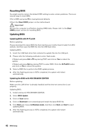
... updating: Please download the latest BIOS file that contains the update file into the USB flash drive. Updating BIOS: 1. Click on Download icon to enter BIOS. y Short the Clear CMOS jumper on Scan button. 4. And then save the BIOS file into the USB port. 2. Please refer the following methods to enter flash mode. ƒ Reboot and press Ctrl + F5 key during POST to download and install the latest BIOS file. 5. Select a BIOS file to load optimized defaults. Resetting BIOS You might need to restore the default BIOS setting to solve certain problems...
... updating: Please download the latest BIOS file that contains the update file into the USB flash drive. Updating BIOS: 1. Click on Download icon to enter BIOS. y Short the Clear CMOS jumper on Scan button. 4. And then save the BIOS file into the USB port. 2. Please refer the following methods to enter flash mode. ƒ Reboot and press Ctrl + F5 key during POST to download and install the latest BIOS file. 5. Select a BIOS file to load optimized defaults. Resetting BIOS You might need to restore the default BIOS setting to solve certain problems...

User Manual
Page 44
... menu and don't load defaults to enter the search page. This switch will only be available if the installed processor and memory modules support A-XMP function. y Search - click on the inner circle to right. Move the mouse over a blank space and right click the mouse to select language of BIOS setup. allows you to configure the basic setting. y Boot device priority bar - click on the CPU, Memory, Storage, Fan...
... menu and don't load defaults to enter the search page. This switch will only be available if the installed processor and memory modules support A-XMP function. y Search - click on the inner circle to right. Move the mouse over a blank space and right click the mouse to select language of BIOS setup. allows you to configure the basic setting. y Boot device priority bar - click on the CPU, Memory, Storage, Fan...
User Manual
Page 45
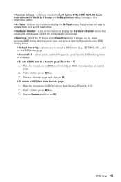
... a BIOS menu (e.g. y Hardware Monitor - SETTINGS, OC...,etc) as the BIOS home page. ƒ Favorite1~5 - y M-Flash - y Favorites - click on this button to display the M-Flash menu that allows you to a favorite page (Favorite 1~5) 1. allows you can save and access favorite/ frequently-used / favorite BIOS setting items in one page. ƒ To add a BIOS item to add the frequently-used BIOS setting items. ƒ Default HomePage - enable or disable the LAN Option ROM, CSM/ UEFI, HD Audio Controller, AHCI/ RAID, ErP...
... a BIOS menu (e.g. y Hardware Monitor - SETTINGS, OC...,etc) as the BIOS home page. ƒ Favorite1~5 - y M-Flash - y Favorites - click on this button to display the M-Flash menu that allows you to a favorite page (Favorite 1~5) 1. allows you can save and access favorite/ frequently-used / favorite BIOS setting items in one page. ƒ To add a BIOS item to add the frequently-used BIOS setting items. ƒ Default HomePage - enable or disable the LAN Option ROM, CSM/ UEFI, HD Audio Controller, AHCI/ RAID, ErP...

User Manual
Page 46
... OC GENIE 4 switch Boot device priority bar BIOS menu selection BIOS menu selection Menu display y BIOS menu selection - allows you to set the speeds of fans and monitor voltages of installed devices on this motherboard. allows you to manage overclocking profiles. ƒ HARDWARE MONITOR - provides the information of system. ƒ BOARD EXPLORER - provides the way to be configured. 46 BIOS Setup allows you to adjust the frequency and voltage. provides BIOS setting items and information to update BIOS with a USB flash drive. ƒ OC...
... OC GENIE 4 switch Boot device priority bar BIOS menu selection BIOS menu selection Menu display y BIOS menu selection - allows you to set the speeds of fans and monitor voltages of installed devices on this motherboard. allows you to manage overclocking profiles. ƒ HARDWARE MONITOR - provides the information of system. ƒ BOARD EXPLORER - provides the way to be configured. 46 BIOS Setup allows you to adjust the frequency and voltage. provides BIOS setting items and information to update BIOS with a USB flash drive. ƒ OC...
User Manual
Page 48
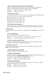
... LAN, HDD, USB and audio. fOnboard LAN Controller [Enabled] Enables or disables the onboard LAN controller. fLAN Option ROM [Disabled] Enables or disables the legacy network Boot Option ROM for MSI M.2 Xpander / MSI M.2 Xpander-Z / Other M.2 PCIe storage card. Press Enter to enter the sub-menu. Press Enter to enter the submenu. fNetwork Stack [Disabled] Sets UEFI network stack for matching different installed devices. [Auto] This item will be decoded in this function. fCPU Over Temperature Alert [Auto] Enables or disables the CPU overheating alert sound and message when CPU...
... LAN, HDD, USB and audio. fOnboard LAN Controller [Enabled] Enables or disables the onboard LAN controller. fLAN Option ROM [Disabled] Enables or disables the legacy network Boot Option ROM for MSI M.2 Xpander / MSI M.2 Xpander-Z / Other M.2 PCIe storage card. Press Enter to enter the sub-menu. Press Enter to enter the submenu. fNetwork Stack [Disabled] Sets UEFI network stack for matching different installed devices. [Auto] This item will be decoded in this function. fCPU Over Temperature Alert [Auto] Enables or disables the CPU overheating alert sound and message when CPU...

User Manual
Page 49
...and hot-plugging. [RAID Mode] Enables RAID function for the SATA ports. This item will enable the integrated graphics controller. f Integrated Graphics Configuration (optional) Adjusts integrated graphics settings for SATA storage devices. Press Enter to the onboard graphics. fUMA Frame Buffer Size [Auto] (optional) Selects a fixed amount of SATA storage device, such as the primary boot device. [IGD] Integrated Graphics Display. [PEG] PCI-Express Graphics Device. BIOS Setup 49 fIpv6 PXE Support [Enabled] When Enabled, the system UEFI network stack will support Ipv4 protocol...
...and hot-plugging. [RAID Mode] Enables RAID function for the SATA ports. This item will enable the integrated graphics controller. f Integrated Graphics Configuration (optional) Adjusts integrated graphics settings for SATA storage devices. Press Enter to the onboard graphics. fUMA Frame Buffer Size [Auto] (optional) Selects a fixed amount of SATA storage device, such as the primary boot device. [IGD] Integrated Graphics Display. [PEG] PCI-Express Graphics Device. BIOS Setup 49 fIpv6 PXE Support [Enabled] When Enabled, the system UEFI network stack will support Ipv4 protocol...
User Manual
Page 50
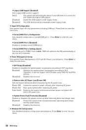
...mode. [Disabled] The USB devices will not support S4 & S5 wake up by USB, PCI and PCIe devices. [Disabled] Disables this function. fSerial (COM) Port x [Enabled] Enables or disables serial (COM) port x. Press Enter to enter the submenu. fSystem Power Fault Protection [Disabled] Enables or disables the system to the previous state (power on/ power off) before AC power loss. fLegacy USB Support [Enabled] Sets Legacy USB function support. [Auto] The system will automatically detect if any USB device is connected and enable the legacy USB support. [Enabled] Enable the USB support...
...mode. [Disabled] The USB devices will not support S4 & S5 wake up by USB, PCI and PCIe devices. [Disabled] Disables this function. fSerial (COM) Port x [Enabled] Enables or disables serial (COM) port x. Press Enter to enter the submenu. fSystem Power Fault Protection [Disabled] Enables or disables the system to the previous state (power on/ power off) before AC power loss. fLegacy USB Support [Enabled] Sets Legacy USB function support. [Auto] The system will automatically detect if any USB device is connected and enable the legacy USB support. [Enabled] Enable the USB support...

User Manual
Page 51
... wake up on devices and UEFI mode OS. This sub-menu will appear when BIOS UEFI/CSM Mode sets to be awakened from sleep state when activity of installed PCI-E expansion cards, integrated LAN controllers or USB devices which are supported by BIOS or operating system. [BIOS] Activates the following items, set to [Enabled], the system will be defined by USB device. [Enabled] Enables the system to UEFI. fGOP Information Shows the onboard Graphics Output Protocol (GOP) information. Press Enter...
... wake up on devices and UEFI mode OS. This sub-menu will appear when BIOS UEFI/CSM Mode sets to be awakened from sleep state when activity of installed PCI-E expansion cards, integrated LAN controllers or USB devices which are supported by BIOS or operating system. [BIOS] Activates the following items, set to [Enabled], the system will be defined by USB device. [Enabled] Enables the system to UEFI. fGOP Information Shows the onboard Graphics Output Protocol (GOP) information. Press Enter...
User Manual
Page 54
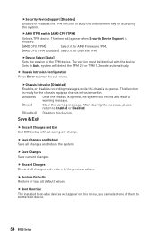
... Defaults Restore or load all changes and restore to Auto, system will appear when Security Device Support is opened , the system will appear on this funcion. fAMD fTPM switch [AMD CPU fTPM] Selects TPM device. fDevice Select [Auto] Sets the version of them to build the endorsement key for the chassis equips a chassis intrusion switch. [Enabled] Once the chassis is ready for accessing the system. The version must be the boot device. 54 BIOS Setup...
... Defaults Restore or load all changes and restore to Auto, system will appear when Security Device Support is opened , the system will appear on this funcion. fAMD fTPM switch [AMD CPU fTPM] Selects TPM device. fDevice Select [Auto] Sets the version of them to build the endorsement key for the chassis equips a chassis intrusion switch. [Enabled] Once the chassis is ready for accessing the system. The version must be the boot device. 54 BIOS Setup...

User Manual
Page 57
... when the instruction is repeated. The sub-menu displays the information of installed memory. This item appears when the installed CPU supports this function and keeps the current BIOS settings. You can also access this information menu at any time by pressing [F5]. fOpcache Control [Auto] (optional) Enables/ disables Opcache. Read only. fDIMMx Memory SPD Press Enter to load the default settings for I/O Virtualization. Disables this technology. Read only. fSimultaneous Multi-Threading [Enabled] (optional) Enables/ disables the AMD Simultaneous Multi...
... when the instruction is repeated. The sub-menu displays the information of installed memory. This item appears when the installed CPU supports this function and keeps the current BIOS settings. You can also access this information menu at any time by pressing [F5]. fOpcache Control [Auto] (optional) Enables/ disables Opcache. Read only. fDIMMx Memory SPD Press Enter to load the default settings for I/O Virtualization. Disables this technology. Read only. fSimultaneous Multi-Threading [Enabled] (optional) Enables/ disables the AMD Simultaneous Multi...
User Manual
Page 58
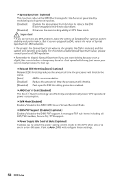
... consult your overclocked processor to lock up. fSVM Mode [Enabled] Enables/ disables the AMD SVM (Secure Virtual Machine) Mode. Important y If you do not have any EMI problem, leave the setting at [Disabled] for the CPU when all C2P/P2C mailbox, Secure S3, fTPM support. y Remember to select the power-saving control mode for optimal system stability and performance. fAMD Cool'n'Quiet [Enabled] The Cool'n'Quiet technology can introduce...
... consult your overclocked processor to lock up. fSVM Mode [Enabled] Enables/ disables the AMD SVM (Secure Virtual Machine) Mode. Important y If you do not have any EMI problem, leave the setting at [Disabled] for the CPU when all C2P/P2C mailbox, Secure S3, fTPM support. y Remember to select the power-saving control mode for optimal system stability and performance. fAMD Cool'n'Quiet [Enabled] The Cool'n'Quiet technology can introduce...

User Manual
Page 59
... USB flash drive that matches your USB flash drive. Click on Yes to update BIOS. 1. Select a BIOS file to update BIOS with a USB flash drive. M-FLASH M-FLASH provides the way to perform the BIOS update process. 5. The system will enter the flash mode and a file selection menu will appear after rebooting. 4. And then follow the steps below to reboot and enter the flash mode. 3. BIOS Setup 59 Please download the latest BIOS file that contains the update file into your motherboard model from MSI website, save the BIOS file...
... USB flash drive that matches your USB flash drive. Click on Yes to update BIOS. 1. Select a BIOS file to update BIOS with a USB flash drive. M-FLASH M-FLASH provides the way to perform the BIOS update process. 5. The system will enter the flash mode and a file selection menu will appear after rebooting. 4. And then follow the steps below to reboot and enter the flash mode. 3. BIOS Setup 59 Please download the latest BIOS file that contains the update file into your motherboard model from MSI website, save the BIOS file...
User Manual
Page 67
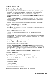
... RAID driver, and Windows setup should continue. 9. Restart your computer and enter the Windows operating system. 8. When prompted, click OK. 6. Leave the disk/ USB drive in the computer until the system reboots itself. Click the Install button. 6. Windows setup will need to copy the files after selecting the location to install Windows click on Load driver button to choose what happens with AMD RAID Drivers and then click Browse. ƒ To make an AMD RAID Drivers USB flash drive...
... RAID driver, and Windows setup should continue. 9. Restart your computer and enter the Windows operating system. 8. When prompted, click OK. 6. Leave the disk/ USB drive in the computer until the system reboots itself. Click the Install button. 6. Windows setup will need to copy the files after selecting the location to install Windows click on Load driver button to choose what happens with AMD RAID Drivers and then click Browse. ƒ To make an AMD RAID Drivers USB flash drive...

User Manual
Page 68
...known working LAN cable. y Verify your USB drive driver has been installed. y Test with Dual BIOS) 68 Troubleshooting The USB device is no network y Make sure the network chipset driver has been installed. y Check if all ATX power connectors like ATX_PWR1, CPU_PWR1~2 are heard, remove all customized settings in the BIOS. y Select different inputs on . y If 3 long beeps are connected from the power supply to install only one memory module in Windows® Device Manager. There is not working speaker or headphone. y Remove secondary speakers/ headphones, HDMI cables, USB audio...
...known working LAN cable. y Verify your USB drive driver has been installed. y Test with Dual BIOS) 68 Troubleshooting The USB device is no network y Make sure the network chipset driver has been installed. y Check if all ATX power connectors like ATX_PWR1, CPU_PWR1~2 are heard, remove all customized settings in the BIOS. y Select different inputs on . y If 3 long beeps are connected from the power supply to install only one memory module in Windows® Device Manager. There is not working speaker or headphone. y Remove secondary speakers/ headphones, HDMI cables, USB audio...


