
User Guide
Page 6
.../s, 100Mb/s - Compliant with AC97 v2.2 spec. Supports ACPI Power Management BIOS l The mainboard BIOS provides Plug & Play BIOS which detects the peripheral devices and expansion cards of the board automatically l The mainboard provides a Desktop Management Interface (DMI) function which records your mainboard specifications Dimension l Micro-ATX Form Factor: 245mm x 190mm Mounting l 6 standard mounting holes 2 Compliant...
.../s, 100Mb/s - Compliant with AC97 v2.2 spec. Supports ACPI Power Management BIOS l The mainboard BIOS provides Plug & Play BIOS which detects the peripheral devices and expansion cards of the board automatically l The mainboard provides a Desktop Management Interface (DMI) function which records your mainboard specifications Dimension l Micro-ATX Form Factor: 245mm x 190mm Mounting l 6 standard mounting holes 2 Compliant...
User Guide
Page 10
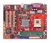
...each side of 1GB. or double-sided modules to avoid damage. Installing DDR Modules 1. Insert the DIMM memory module vertically into the DIMM slot. MSI Reminds You... 1. Do not touch the CPU socket pins to meet your own needs. Memory The mainboard provides 2 slots for 184-pin DDR ...close. 6 Check the information in the socket. 3. You can be pressed down to http://www.msi.com.tw/program/products/mainboard/mbd/pro_mbd_trp_list.php for the CPU temperature. 3. Then push it in BIOS for compatible DDR modules. Connect the fan power cable from the mounted fan to 2GB. Confirm ...
...each side of 1GB. or double-sided modules to avoid damage. Installing DDR Modules 1. Insert the DIMM memory module vertically into the DIMM slot. MSI Reminds You... 1. Do not touch the CPU socket pins to meet your own needs. Memory The mainboard provides 2 slots for 184-pin DDR ...close. 6 Check the information in the socket. 3. You can be pressed down to http://www.msi.com.tw/program/products/mainboard/mbd/pro_mbd_trp_list.php for the CPU temperature. 3. Then push it in BIOS for compatible DDR modules. Connect the fan power cable from the mounted fan to 2GB. Confirm ...
User Guide
Page 12
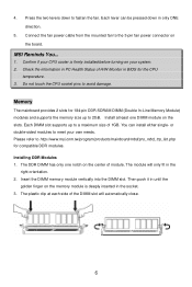
...133 function. The first hard drive should be short. Chassis Intrusion Switch Connector: JCASE1 This connector is Ground and should always be connected to IDE1. MSI Reminds You... You must use a specially designed fan with +12V. Fan Power Connectors: CPU_FAN/SYS_FAN The CPU_FAN (processor fan) and SYS_FAN (system ... disks on -board, you must configure second hard drive to Slave mode by setting its jumper. To clear the warning, you must enter the BIOS setting and clear the status. IDE Connectors: IDE1 & IDE2 The mainboard has a 32-bit Enhanced PCI IDE and Ultra DMA 33/66/100...
...133 function. The first hard drive should be short. Chassis Intrusion Switch Connector: JCASE1 This connector is Ground and should always be connected to IDE1. MSI Reminds You... You must use a specially designed fan with +12V. Fan Power Connectors: CPU_FAN/SYS_FAN The CPU_FAN (processor fan) and SYS_FAN (system ... disks on -board, you must configure second hard drive to Slave mode by setting its jumper. To clear the warning, you must enter the BIOS setting and clear the status. IDE Connectors: IDE1 & IDE2 The mainboard has a 32-bit Enhanced PCI IDE and Ultra DMA 33/66/100...
User Guide
Page 15
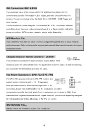
... typically connected to make any necessary hardware or software settings for the expansion card to the PCI bus INT A# ~ INT D# pins as jumpers, switches or BIOS configuration.
... typically connected to make any necessary hardware or software settings for the expansion card to the PCI bus INT A# ~ INT D# pins as jumpers, switches or BIOS configuration.
User Guide
Page 16
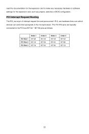
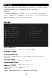
... on the screen, press key to enter Setup, restart the system by simultaneously pressing , , and keys. Advanced BIOS Features Use this menu to specify your settings for basic system configurations, such as time, date etc. Advanced Chipset Features Use this menu to setup ...
... on the screen, press key to enter Setup, restart the system by simultaneously pressing , , and keys. Advanced BIOS Features Use this menu to specify your settings for basic system configurations, such as time, date etc. Advanced Chipset Features Use this menu to setup ...
User Guide
Page 17
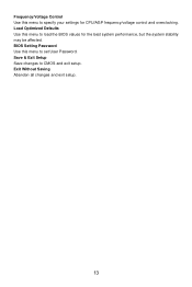
Save & Exit Setup Save changes to CMOS and exit setup. Exit Without Saving Abandon all changes and exit setup. 13 Load Optimized Defaults Use this menu to set User Password. BIOS Setting Password Use this menu to load the BIOS values for CPU/AGP frequency/voltage control and overclocking. Frequency/Voltage Control Use this menu to specify your settings for the best system performance, but the system stability may be affected.
Save & Exit Setup Save changes to CMOS and exit setup. Exit Without Saving Abandon all changes and exit setup. 13 Load Optimized Defaults Use this menu to set User Password. BIOS Setting Password Use this menu to load the BIOS values for CPU/AGP frequency/voltage control and overclocking. Frequency/Voltage Control Use this menu to specify your settings for the best system performance, but the system stability may be affected.
User Guide
Page 61
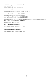
PNP/PCI Configurations(PnP/PCI PnP/PCI H/W Monitor PC CPU Frequency/Voltage Control Load Optimized Defaults BIOS BIOS Setting Password(BIOS BIOS Save & Exit Setup CMOS Setup 程序。 Exit Without Saving CMOS Setup 程序。 57
PNP/PCI Configurations(PnP/PCI PnP/PCI H/W Monitor PC CPU Frequency/Voltage Control Load Optimized Defaults BIOS BIOS Setting Password(BIOS BIOS Save & Exit Setup CMOS Setup 程序。 Exit Without Saving CMOS Setup 程序。 57
User Guide
Page 76
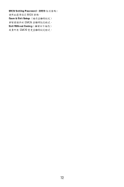
BIOS Setting Password(BIOS BIOS 密碼。 Save & Exit Setup CMOS Exit Without Saving CMOS 72
BIOS Setting Password(BIOS BIOS 密碼。 Save & Exit Setup CMOS Exit Without Saving CMOS 72
User Guide
Page 80
PCI 2.2 準拠 - AC'97 v2.2 準拠 LAN l Realtek 8201CL PHY - 10 / 100BASE-T - l 6穴 76 l - S-ATA 150 ×2 Audio l VIA VT8237R 内蔵 AC'97 l 5.1 Realtek ALC655 - ACPI BIOS l Plug & Play l DMI (Desktop Management Interface Dimension l ATX : 24.5 cm x 19.0 cm. FDD ポート×1 (360K, 720K, 1.2M, 1.44M and 2.88M FDD 1 1 VGA ポート(D-Sub15pin) ×1 1 (SPP / EPP / ECP USB 2.0 ポート×4 (4 Line-In / Line-Out / Mic RJ-45 LAN 1 (10/100BASE-T) -
PCI 2.2 準拠 - AC'97 v2.2 準拠 LAN l Realtek 8201CL PHY - 10 / 100BASE-T - l 6穴 76 l - S-ATA 150 ×2 Audio l VIA VT8237R 内蔵 AC'97 l 5.1 Realtek ALC655 - ACPI BIOS l Plug & Play l DMI (Desktop Management Interface Dimension l ATX : 24.5 cm x 19.0 cm. FDD ポート×1 (360K, 720K, 1.2M, 1.44M and 2.88M FDD 1 1 VGA ポート(D-Sub15pin) ×1 1 (SPP / EPP / ECP USB 2.0 ポート×4 (4 Line-In / Line-Out / Mic RJ-45 LAN 1 (10/100BASE-T) -

User Guide
Page 83
CPU 2 90 3 1 と CPU CPU 4. Socket 478 CPU 1. CPU CPU が正し 5. CPU CPU CPU CPU 1 CPU 2 3 4 4. 2 1 3 ●CPU 1 CPU および CPU 2 BIOS PC Health Status of H/W Monitor」で CPU の温 3 CPU 79
CPU 2 90 3 1 と CPU CPU 4. Socket 478 CPU 1. CPU CPU が正し 5. CPU CPU CPU CPU 1 CPU 2 3 4 4. 2 1 3 ●CPU 1 CPU および CPU 2 BIOS PC Health Status of H/W Monitor」で CPU の温 3 CPU 79

User Guide
Page 88
BIOS Setup BIOS とは Basic Input Output System BIOS OS BIOS BIOS POST (Power On Self Test DEL BIOS DEL: Setup BIOS Delete BIOS Main Page Standard CMOS Features Advanced BIOS Features Advanced Chipset Features Integrated Peripherals IDE 84
BIOS Setup BIOS とは Basic Input Output System BIOS OS BIOS BIOS POST (Power On Self Test DEL BIOS DEL: Setup BIOS Delete BIOS Main Page Standard CMOS Features Advanced BIOS Features Advanced Chipset Features Integrated Peripherals IDE 84
User Guide
Page 89
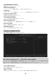
Power Management Features PNP/PCI Configurations PCI H/W Monitor CPU Frequency/Voltage Control Load Optimized Defaults BIOS Setting Password BIOS Save & Exit Setup BIOS Exit Without Saving Frequency/Voltage Control CPU / AGP / DRAM ●「Frequency/Voltage Control Current FSB Frequency 現在の FSB Adjust CPU Ratio CPU 8 倍から 50 85
Power Management Features PNP/PCI Configurations PCI H/W Monitor CPU Frequency/Voltage Control Load Optimized Defaults BIOS Setting Password BIOS Save & Exit Setup BIOS Exit Without Saving Frequency/Voltage Control CPU / AGP / DRAM ●「Frequency/Voltage Control Current FSB Frequency 現在の FSB Adjust CPU Ratio CPU 8 倍から 50 85


