User Guide
Page 8
... Technical Support ...ii Safety Instructions ...iii FCC-B Radio Frequency Interference Statement iv W EEE (Waste Electrical and Electronic Equipment) Statement v Chapter 1. Hardware Setup 2-1 Quick Components Guide 2-2 CPU (Central Processing Unit 2-3 Memory ...2-7 Power Supply ...2-9 Back Panel ...2-11 Connectors ...2-13 Jumper ...2-20 Slots ...2-21 Chapter 3 BIOS Setup 3-1 Entering Setup ...3-2 The Main Menu ...3-4 Standard CMOS...
... Technical Support ...ii Safety Instructions ...iii FCC-B Radio Frequency Interference Statement iv W EEE (Waste Electrical and Electronic Equipment) Statement v Chapter 1. Hardware Setup 2-1 Quick Components Guide 2-2 CPU (Central Processing Unit 2-3 Memory ...2-7 Power Supply ...2-9 Back Panel ...2-11 Connectors ...2-13 Jumper ...2-20 Slots ...2-21 Chapter 3 BIOS Setup 3-1 Entering Setup ...3-2 The Main Menu ...3-4 Standard CMOS...

User Guide
Page 11
... with Azalia 1.0 Spec IDE - 1 IDE port by Realtek® RTL8111C IEEE 1394 (optional) - Supports Intel® Hyper-Threading (HT) Technology (For the latest information about CPU, please visit ht t p : / / g lobal. p hp ?f un c = c p uf or m 2 ) Supported FSB - 1333/ 1066/ 800 MHz Chipset - Supports 10/100/1000 Fast Ethernet by JMicron JMB368, supports...
... with Azalia 1.0 Spec IDE - 1 IDE port by Realtek® RTL8111C IEEE 1394 (optional) - Supports Intel® Hyper-Threading (HT) Technology (For the latest information about CPU, please visit ht t p : / / g lobal. p hp ?f un c = c p uf or m 2 ) Supported FSB - 1333/ 1066/ 800 MHz Chipset - Supports 10/100/1000 Fast Ethernet by JMicron JMB368, supports...
User Guide
Page 17
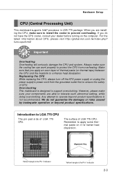
...damages or risks caused by inadequate operation or beyond product specifications is the Pin 1 indicator 2-3 Replaceing the CPU While replacing the CPU, always turn off the ATX power supply or unplug the power supply's power cord from overheating. Remember to ensure the safety of thermal ... Pin 1 indicator Yellow triangle is not recommended. Hardware Setup CPU (Central Processing Unit) This mainboard supports Intel® processor in LGA 775 package. For the latest information about CPU, please visit http://global.msi.com.tw/index.php? Any attempt to operate beyond product ...
...damages or risks caused by inadequate operation or beyond product specifications is the Pin 1 indicator 2-3 Replaceing the CPU While replacing the CPU, always turn off the ATX power supply or unplug the power supply's power cord from overheating. Remember to ensure the safety of thermal ... Pin 1 indicator Yellow triangle is not recommended. Hardware Setup CPU (Central Processing Unit) This mainboard supports Intel® processor in LGA 775 package. For the latest information about CPU, please visit http://global.msi.com.tw/index.php? Any attempt to operate beyond product ...
User Guide
Page 18
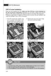
...overheating. The CPU socket has a plastic cap on CPU before turning on your CPU packing. 2-4 Open the load lever. Do not touch the CPU socket pins to install the CPU & cooler correctly. The pins of the CPU land side cover depends on your CPU & mainboard. 1. Confirm if your CPU cooler is firmly... installed before installing the heat sink/cooler fan for better heat dispersion. MS-7530 Mainboard CPU & Cooler Installation W hen you install the CPU, always cover it to protect the contact from lever hinge side (as the arrow shows). 3. Remove the cap from damage....
...overheating. The CPU socket has a plastic cap on CPU before turning on your CPU packing. 2-4 Open the load lever. Do not touch the CPU socket pins to install the CPU & cooler correctly. The pins of the CPU land side cover depends on your CPU & mainboard. 1. Confirm if your CPU cooler is firmly... installed before installing the heat sink/cooler fan for better heat dispersion. MS-7530 Mainboard CPU & Cooler Installation W hen you install the CPU, always cover it to protect the contact from lever hinge side (as the arrow shows). 3. Remove the cap from damage....
User Guide
Page 19
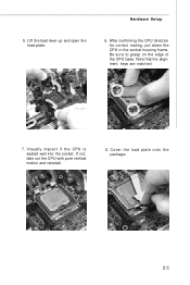
Lift the load lever up and open the load plate. 6. Be sure to grasp on the edge of the CPU base. Note that the alignment keys are matched. After confirming the CPU direction for correct mating, put down the CPU in the socket housing frame. alignment key 7. If not, take out the CPU with pure vertical motion and reinstall. 8. Cover the load plate onto the p ac k age. 2-5 Visually inspect if the CPU is seated well into the socket. Hardware Setup 5.
Lift the load lever up and open the load plate. 6. Be sure to grasp on the edge of the CPU base. Note that the alignment keys are matched. After confirming the CPU direction for correct mating, put down the CPU in the socket housing frame. alignment key 7. If not, take out the CPU with pure vertical motion and reinstall. 8. Cover the load plate onto the p ac k age. 2-5 Visually inspect if the CPU is seated well into the socket. Hardware Setup 5.
User Guide
Page 20
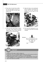
...lever lightly onto the load plate, and then secure the lever with the hook under retention tab. 10. Read the CPU status in this section are correctly inserted. Whenever CPU is not installed, always protect your mainboard may vary depending on the mainboard with the plastic cap covered (shown in...Hook Important 1. Mainboard photos shown in BIOS (Chapter 3). 2. Push down the cooler until its four clips get wedged into the holes of the CPU/ cooler installation only. Press down to avoid damaging. 3. Turn over the mainboard to lock the hooks. 12. The appearance of your...
...lever lightly onto the load plate, and then secure the lever with the hook under retention tab. 10. Read the CPU status in this section are correctly inserted. Whenever CPU is not installed, always protect your mainboard may vary depending on the mainboard with the plastic cap covered (shown in...Hook Important 1. Mainboard photos shown in BIOS (Chapter 3). 2. Push down the cooler until its four clips get wedged into the holes of the CPU/ cooler installation only. Press down to avoid damaging. 3. Turn over the mainboard to lock the hooks. 12. The appearance of your...

User Guide
Page 23
... Power Connector: JPWR2 This power connector is also a foolproof design on pin 11, 12, 23 & 24 to the CPU. If you'd like to use the 20-pin ATX power supply as you to ensure stable operation of the mainboard. 2. Power supply of the power supply is highly recommended for system ...stability. 2-9 Hardware Setup Power Supply ATX 24-Pin Power Connector: JPWR1 This connector allows you like. To connect the ATX 24-pin power supply, make sure the plug of 350 watts (and above) is inserted in the proper...
... Power Connector: JPWR2 This power connector is also a foolproof design on pin 11, 12, 23 & 24 to the CPU. If you'd like to use the 20-pin ATX power supply as you to ensure stable operation of the mainboard. 2. Power supply of the power supply is highly recommended for system ...stability. 2-9 Hardware Setup Power Supply ATX 24-Pin Power Connector: JPWR1 This connector allows you like. To connect the ATX 24-pin power supply, make sure the plug of 350 watts (and above) is inserted in the proper...
User Guide
Page 29
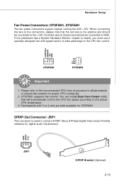
...the positive and should be connected to take advantage of the CPU fan control. Hardware Setup Fan Power Connectors: CPUFAN1, SYSFAN1 The fan power connectors support system cooling fan with 3 or 4 pins are both available for digital audio transmission. CONTROL SENSOR +12V GND CPUFAN1 NC +12V ...GND SYSFAN1 Important 1. GND SPDIF VCC JSP1 S/PDIF Bracket (Optional) 2-15 Please refer to the actual CPU temperature. 3. You can install Dual Core Center utility that...
...the positive and should be connected to take advantage of the CPU fan control. Hardware Setup Fan Power Connectors: CPUFAN1, SYSFAN1 The fan power connectors support system cooling fan with 3 or 4 pins are both available for digital audio transmission. CONTROL SENSOR +12V GND CPUFAN1 NC +12V ...GND SYSFAN1 Important 1. GND SPDIF VCC JSP1 S/PDIF Bracket (Optional) 2-15 Please refer to the actual CPU temperature. 3. You can install Dual Core Center utility that...

User Guide
Page 36
... on NVIDIA's industry-leading SLI technology, delivers multi-GPU benefits when an NVIDIA mainboard GPU is combined with the Vista operating system. 2. AMD Phenom CPU or Intel CPU running at FSB 1333 MHz or higher - 2 x 1 GB of the graphic card. The chipset will share the rendering load with the graphic card and...
... on NVIDIA's industry-leading SLI technology, delivers multi-GPU benefits when an NVIDIA mainboard GPU is combined with the Vista operating system. 2. AMD Phenom CPU or Intel CPU running at FSB 1333 MHz or higher - 2 x 1 GB of the graphic card. The chipset will share the rendering load with the graphic card and...
User Guide
Page 44
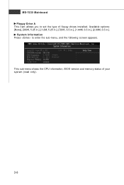
This sub-menu shows the CPU information, BIOS version and memory status of floppy drives installed. Available options: [None], [360K, 5.25 in.], [1.2M, 5.25 in.], [720K, 3.5 in.], [1.44M, 3.5 in.], [2.88M, 3.5 in.]. System Information Press to set the type of your system (read only). 3-8 MS-7530 Mainboard Floppy Drive A This item allows you to enter the sub-menu, and the following screen appears.
This sub-menu shows the CPU information, BIOS version and memory status of floppy drives installed. Available options: [None], [360K, 5.25 in.], [1.2M, 5.25 in.], [720K, 3.5 in.], [1.44M, 3.5 in.], [2.88M, 3.5 in.]. System Information Press to set the type of your system (read only). 3-8 MS-7530 Mainboard Floppy Drive A This item allows you to enter the sub-menu, and the following screen appears.

User Guide
Page 46
... graphics adapter. W hen set the item to higher values, every PCI device can to enable it via the various ACPI methods. 3-10 CPU Feature Press to read the CPU power consumption while idle. Set Limit CPUID MaxVal to 3 The Max CPUID Value Limit is designed to limit the listed speed of the...
... graphics adapter. W hen set the item to higher values, every PCI device can to enable it via the various ACPI methods. 3-10 CPU Feature Press to read the CPU power consumption while idle. Set Limit CPUID MaxVal to 3 The Max CPUID Value Limit is designed to limit the listed speed of the...
User Guide
Page 51
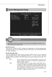
... in S1(POS) or S3(STR) fashion through the setting of system configuration and open applications/files are : [S1] The S1 sleep mode is lost (CPU or chipset) and hardware main- formation of this section are available only when your BIOS supports S3 sleep mode. tains all system context. [S3] The...
... in S1(POS) or S3(STR) fashion through the setting of system configuration and open applications/files are : [S1] The S1 sleep mode is lost (CPU or chipset) and hardware main- formation of this section are available only when your BIOS supports S3 sleep mode. tains all system context. [S3] The...
User Guide
Page 53
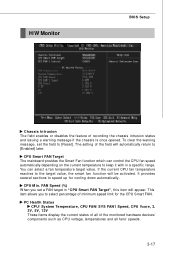
... Target", this item will appear. The setting of minimum speed limit for cooling down automatically . You can control the CPU fan speed automatically depending on the current temperature to [Reset]. H/W Monitor BIOS Setup Chassis Intrusion The field enables or disables... the feature of the monitored hardware devices/ components such as CPU voltage, temperatures and all fans' speeds. 3-17 It provides several sections to [Enabled] later. CPU Smart FAN Target The mainboard provides the Smart Fan function which can select a fan temperature...
... Target", this item will appear. The setting of minimum speed limit for cooling down automatically . You can control the CPU fan speed automatically depending on the current temperature to [Reset]. H/W Monitor BIOS Setup Chassis Intrusion The field enables or disables... the feature of the monitored hardware devices/ components such as CPU voltage, temperatures and all fans' speeds. 3-17 It provides several sections to [Enabled] later. CPU Smart FAN Target The mainboard provides the Smart Fan function which can select a fan temperature...
User Guide
Page 55
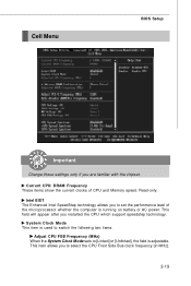
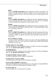
...appear after you are familiar with the chipset. Cell Menu BIOS Setup Important Change these settings only if you installed the CPU which support speedstep technology. Current CPU/ DRAM Frequency These items show the current clocks of the microprocessor whether the computer is adjustable. System Clock Mode This item... is used to switch the following two items. Adjust CPU FSB Frequency (M Hz) When the System Clock Mode sets to select the CPU Front Side Bus clock frequency (in MHz). 3-19 Read-only. This item allows you to set the...
...appear after you are familiar with the chipset. Cell Menu BIOS Setup Important Change these settings only if you installed the CPU which support speedstep technology. Current CPU/ DRAM Frequency These items show the current clocks of the microprocessor whether the computer is adjustable. System Clock Mode This item... is used to switch the following two items. Adjust CPU FSB Frequency (M Hz) When the System Clock Mode sets to select the CPU Front Side Bus clock frequency (in MHz). 3-19 Read-only. This item allows you to set the...
User Guide
Page 56
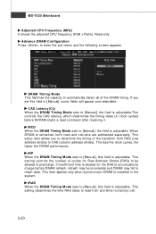
... rows and columns are addressed separately. This setup item allows you set this field to memory cell. 3-20 MS-7530 Mainboard Adjusted CPU Frequency (M Hz) It shows the adjusted CPU frequency (FSB x Ratio). Advance DRAM Configuration Press to CAS (column address strobe). The less the clock cycles, the faster the DRAM performance...
... rows and columns are addressed separately. This setup item allows you set this field to memory cell. 3-20 MS-7530 Mainboard Adjusted CPU Frequency (M Hz) It shows the adjusted CPU frequency (FSB x Ratio). Advance DRAM Configuration Press to CAS (column address strobe). The less the clock cycles, the faster the DRAM performance...
User Guide
Page 57
Allows sense amplifiers to restore data to increase the CPU voltage. 3-21 Adjust Memory Clock (M Hz) This item allows you to set System Clock Mode to [Unlinked]. tWR When the DRAM Timing Mode sets to [... starts. 1T/2T Memory Timing This item controls the SDRAM command rate. tWTR When the DRAM Timing Mode sets to [Manual], the field is adjustable. CPU Voltage (V) This item allows you set the Memory frequency (in MHz). Read-only. This item will disappear after you to cells. The rowcycle time determines...
Allows sense amplifiers to restore data to increase the CPU voltage. 3-21 Adjust Memory Clock (M Hz) This item allows you to set System Clock Mode to [Unlinked]. tWR When the DRAM Timing Mode sets to [... starts. 1T/2T Memory Timing This item controls the SDRAM command rate. tWTR When the DRAM Timing Mode sets to [Manual], the field is adjustable. CPU Voltage (V) This item allows you set the Memory frequency (in MHz). Read-only. This item will disappear after you to cells. The rowcycle time determines...

User Guide
Page 58
...the memory voltage can introduce a temporary boost in clock speed which may just cause your local EMI regulation. 3. CPU/LDT Spread Spectrum This setting is used to [Disabled]. W hen overclocking the CPU, always set it to enable or disable the SATA Spread Spectrum feature. SATA Spread Spectrum This setting is used... to enable or disable the CPU Spread Spectrum feature. The greater the Spread Spectrum value is, the greater the EMI is used to set it to lock up. 3-22...
...the memory voltage can introduce a temporary boost in clock speed which may just cause your local EMI regulation. 3. CPU/LDT Spread Spectrum This setting is used to [Disabled]. W hen overclocking the CPU, always set it to enable or disable the SATA Spread Spectrum feature. SATA Spread Spectrum This setting is used... to enable or disable the CPU Spread Spectrum feature. The greater the Spread Spectrum value is, the greater the EMI is used to set it to lock up. 3-22...
User Guide
Page 59
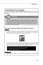
Important This motherboard supports overclocking greatly. Please press any key to continue....... The previous overclocking had failed, and system will determine that the previous overclocking is not recommended. Clear CMOS - Reboot 1. Press the Power button to overclock the CPU and the Memory....damge resulting from failed overclocking... Please note that exceeds product specification is failed and restore the default settings automatically. BIOS Setup CPU and Memory Clock Overclocking The FSB Clock/ Memory Clock & FSB/DRAM ratio are bearable for more information about how to...
Important This motherboard supports overclocking greatly. Please press any key to continue....... The previous overclocking had failed, and system will determine that the previous overclocking is not recommended. Clear CMOS - Reboot 1. Press the Power button to overclock the CPU and the Memory....damge resulting from failed overclocking... Please note that exceeds product specification is failed and restore the default settings automatically. BIOS Setup CPU and Memory Clock Overclocking The FSB Clock/ Memory Clock & FSB/DRAM ratio are bearable for more information about how to...

User Guide
Page 99
... and efforts to develop, helps users to monitor or configure the hardware status of MSI Mainboard & MSI Graphics card in this appendix are for software installation. 4. The appearance in windows, such as CPU/GPU clock, voltage, fan speed and temperature. CD-ROM drive for reference only.... Intel Pentium4 / Celeron, AMD Athlon XP/ Sempron or compatible CPU with PCI Express slot. 2. 256MB system memory. ...
... and efforts to develop, helps users to monitor or configure the hardware status of MSI Mainboard & MSI Graphics card in this appendix are for software installation. 4. The appearance in windows, such as CPU/GPU clock, voltage, fan speed and temperature. CD-ROM drive for reference only.... Intel Pentium4 / Celeron, AMD Athlon XP/ Sempron or compatible CPU with PCI Express slot. 2. 256MB system memory. ...
User Guide
Page 101
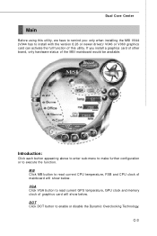
VGA Click VGA button to read current CPU temperature, FSB and CPU clock of the MSI mainboard would be available. MB Click MB button to remind you install a graphics card of other brand, only hardware status of mainboard will show below . ...DOT Click DOT button to execute the function. C-3 If you : only when installing the MSI V044 (V044 has to install with...
VGA Click VGA button to read current CPU temperature, FSB and CPU clock of the MSI mainboard would be available. MB Click MB button to remind you install a graphics card of other brand, only hardware status of mainboard will show below . ...DOT Click DOT button to execute the function. C-3 If you : only when installing the MSI V044 (V044 has to install with...

