User Guide
Page 2
...® is a registered trademark of purchase or local distributor. Alternatively, please try the following help resources for FAQ, technical guide, BIOS updates, driver updates, and other countries. PS/2 and OS®/2 are registered trademarks or trademarks of NVIDIA Corporation in the United ...States and/or other information: http://global.msi.com.tw/index.php? Revision History Revision V1.0 Revision History First release for Europe Date January 2008 Technical Support If a problem...
...® is a registered trademark of purchase or local distributor. Alternatively, please try the following help resources for FAQ, technical guide, BIOS updates, driver updates, and other countries. PS/2 and OS®/2 are registered trademarks or trademarks of NVIDIA Corporation in the United ...States and/or other information: http://global.msi.com.tw/index.php? Revision History Revision V1.0 Revision History First release for Europe Date January 2008 Technical Support If a problem...
User Guide
Page 8
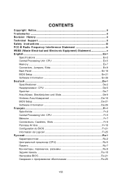
... v English ...En-1 Specifications ...En-2 Central Processing Unit: CPU En-5 Memory ...En-7 Connectors, Jumpers, Slots En-9 Back Panel ...En-18 BIOS Setup ...En-21 Software Information En-25 Deutsch ...De-1 Spezifikationen De-2 Hauptprozessor: CPU De-5 Speicher ...De-7 Anschlüsse, Steckbrücken... und Slots De-9 Hinteres Anschlusspaneel De-18 BIOS Setup ...De-21 Software-Information De-25 Français ...Fr-1 Spécificités ...Fr-2 Central Processing Unit: CPU Fr-5...
... v English ...En-1 Specifications ...En-2 Central Processing Unit: CPU En-5 Memory ...En-7 Connectors, Jumpers, Slots En-9 Back Panel ...En-18 BIOS Setup ...En-21 Software Information En-25 Deutsch ...De-1 Spezifikationen De-2 Hauptprozessor: CPU De-5 Speicher ...De-7 Anschlüsse, Steckbrücken... und Slots De-9 Hinteres Anschlusspaneel De-18 BIOS Setup ...De-21 Software-Information De-25 Français ...Fr-1 Spécificités ...Fr-2 Central Processing Unit: CPU Fr-5...
User Guide
Page 14
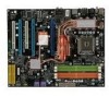
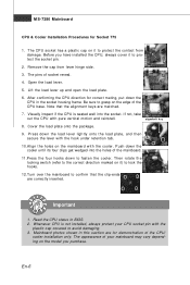
... the socket pin. 2. The appearance of the mainboard. 11.Press the four hooks down the CPU in the socket housing frame. Mainboard photos shown in BIOS. 2. Read the CPU status in this section are for Socket 775 1. En-6 Open the load lever. 5. MS-7380 Mainboard CPU & Cooler Installation Procedures for demonstration...
... the socket pin. 2. The appearance of the mainboard. 11.Press the four hooks down the CPU in the socket housing frame. Mainboard photos shown in BIOS. 2. Read the CPU status in this section are for Socket 775 1. En-6 Open the load lever. 5. MS-7380 Mainboard CPU & Cooler Installation Procedures for demonstration...
User Guide
Page 20
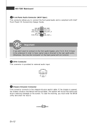
... Intel® Front Panel I/O Connectivity Design Guide. 12 AUD_MIC AUD_GND AUD_MIC_BIAS AUD_VCC AUD_FPout_R AUD_RET_R HP_ON Key AUD_FPout_ L AUD_RET_L 9 10 Important If you must enter the BIOS utility and clear the record. 1 CINTRU GND En-12 R GND L 15 Chassis Intrusion Connector This connector connects to the chassis intrusion switch cable.
... Intel® Front Panel I/O Connectivity Design Guide. 12 AUD_MIC AUD_GND AUD_MIC_BIAS AUD_VCC AUD_FPout_R AUD_RET_R HP_ON Key AUD_FPout_ L AUD_RET_L 9 10 Important If you must enter the BIOS utility and clear the record. 1 CINTRU GND En-12 R GND L 15 Chassis Intrusion Connector This connector connects to the chassis intrusion switch cable.

User Guide
Page 21
... Connector This connector allows you to attach an optional TV-Out bracket that sends/receives 16 bytes FIFOs. You must configure the setting through the BIOS setup to use the infrared function. 12 NC NC VCC5 Ground IRTX IRRX 56 17 Serial Port Connector This connector is compliant with Intel®...
... Connector This connector allows you to attach an optional TV-Out bracket that sends/receives 16 bytes FIFOs. You must configure the setting through the BIOS setup to use the infrared function. 12 NC NC VCC5 Ground IRTX IRRX 56 17 Serial Port Connector This connector is compliant with Intel®...
User Guide
Page 22
...Time Clock) Operating System Booting 3 4 3 4 En-14 Then, detect and initializethe video adapter. 1 2 EarlyChipset Initialization 3 4 BIOS Sign On 1 2 This will hang if the memory mod4 ule is damaged or not in- 3 stalled properly. Memory Detection Test Testing...1 2 Initializing Keyboard Controller. 1 2 Initializing Hard Drive Controller This will initialize IDE drive and 3 4 3 4 controller. 1 2 Testing VGA BIOS 1 2 Initializing Floppy Drive Controller This will start writing VGA sign-on This will initialize Floppy Drive and 3 4 message to the screen. 3 4...
...Time Clock) Operating System Booting 3 4 3 4 En-14 Then, detect and initializethe video adapter. 1 2 EarlyChipset Initialization 3 4 BIOS Sign On 1 2 This will hang if the memory mod4 ule is damaged or not in- 3 stalled properly. Memory Detection Test Testing...1 2 Initializing Keyboard Controller. 1 2 Initializing Hard Drive Controller This will initialize IDE drive and 3 4 3 4 controller. 1 2 Testing VGA BIOS 1 2 Initializing Floppy Drive Controller This will start writing VGA sign-on This will initialize Floppy Drive and 3 4 message to the screen. 3 4...

User Guide
Page 25
... Meanwhile, read the documentation for the expansion card to configure any necessary hardware or software settings for the expansion card, such as jumpers, switches or BIOS configuration. 30 TPM Module Connector This connector connects to the TPM security platform manual for more details and usages. Important When adding or removing expansion...
... Meanwhile, read the documentation for the expansion card to configure any necessary hardware or software settings for the expansion card, such as jumpers, switches or BIOS configuration. 30 TPM Module Connector This connector connects to the TPM security platform manual for more details and usages. Important When adding or removing expansion...
User Guide
Page 29
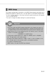
...Chipset vender as A = AMD, I = Intel, V = VIA, N = Nvidia, U = ULi. 7th - 8th digit refers to configure the system for customized features. En-21 English BIOS Setup This chapter provides basic information on the screen during the system booting up , the 1st line appearing after the memory count is usually in... this BIOS was released. You may be slightly different from the latest BIOS and should be held for reference only. 2.Upon boot-up , and requests you to run the Setup program ...
...Chipset vender as A = AMD, I = Intel, V = VIA, N = Nvidia, U = ULi. 7th - 8th digit refers to configure the system for customized features. En-21 English BIOS Setup This chapter provides basic information on the screen during the system booting up , the 1st line appearing after the memory count is usually in... this BIOS was released. You may be slightly different from the latest BIOS and should be held for reference only. 2.Upon boot-up , and requests you to run the Setup program ...
User Guide
Page 30
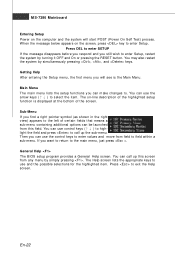
...) process. If you still wish to enter Setup, restart the system by turning it OFF and On or pressing the RESET button. General Help The BIOS setup program provides a General Help screen. Getting Help After entering the Setup m enu, the first menu you can use the control keys to enter values...
...) process. If you still wish to enter Setup, restart the system by turning it OFF and On or pressing the RESET button. General Help The BIOS setup program provides a General Help screen. Getting Help After entering the Setup m enu, the first menu you can use the control keys to enter values...

User Guide
Page 31
...exit setup. English The Main Menu Once you to specify your settings for integrated peripherals. Advanced BIOS Features Use this menu to specify your settings for optim al perform ance of special enhanced features.... power management. The Main Menu allows you enter AMI® or AW ARD® BIOS CMOS Setup Utility, the Main Menu will appear on the screen. Integrated Peripherals Use this menu to ...accept or enter the sub-menu. BIOS Setting Password Use this menu to select from CMOS for stable system perform ance. Use ...
...exit setup. English The Main Menu Once you to specify your settings for integrated peripherals. Advanced BIOS Features Use this menu to specify your settings for optim al perform ance of special enhanced features.... power management. The Main Menu allows you enter AMI® or AW ARD® BIOS CMOS Setup Utility, the Main Menu will appear on the screen. Integrated Peripherals Use this menu to ...accept or enter the sub-menu. BIOS Setting Password Use this menu to select from CMOS for stable system perform ance. Use ...
User Guide
Page 32
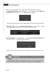
If you need the detailed settings of BIOS, please see the manual in English version on MSI website. En-24 Setup Date/ Time : Select the Standard CMOS Features and press to save the configurations and exit BIOS Setup utility. Important The configuration above are for general use only. MS-...7380 Mainboard W hen enter the BIOS Setup utility, follow the...
If you need the detailed settings of BIOS, please see the manual in English version on MSI website. En-24 Setup Date/ Time : Select the Standard CMOS Features and press to save the configurations and exit BIOS Setup utility. Important The configuration above are for general use only. MS-...7380 Mainboard W hen enter the BIOS Setup utility, follow the...

User Guide
Page 33
... utility and follow the pop-up screen to get the latest drivers and BIOS for better system performance. En-25 English Software Information Take out the Driver/Utility CD that the mainboard supports. Utility m enu - Important Please visit the MSI website to com plete the installation. W ebSite menu- The Utility menu shows...
... utility and follow the pop-up screen to get the latest drivers and BIOS for better system performance. En-25 English Software Information Take out the Driver/Utility CD that the mainboard supports. Utility m enu - Important Please visit the MSI website to com plete the installation. W ebSite menu- The Utility menu shows...


