User Guide
Page 8
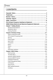
... (Waste Electrical and Electronic Equipment) Statement v Chapter 1 Getting Started 1-1 Mainboard Specifications 1-2 Mainboard Layout 1-4 Packing Checklist 1-5 Chapter 2 Hardware Setup 2-1 Quick Components Guide 2-2 CPU (Central Processing Unit 2-3 Memory 2-7 Power Supply 2-9 Back Panel 2-10 Connectors 2-12 Button 2-20 Switch 2-22 Slots 2-24 LED Status Indicators 2-30 Chapter 3 BIOS Setup 3-1 Entering Setup 3-2 The Main Menu...
... (Waste Electrical and Electronic Equipment) Statement v Chapter 1 Getting Started 1-1 Mainboard Specifications 1-2 Mainboard Layout 1-4 Packing Checklist 1-5 Chapter 2 Hardware Setup 2-1 Quick Components Guide 2-2 CPU (Central Processing Unit 2-3 Memory 2-7 Power Supply 2-9 Back Panel 2-10 Connectors 2-12 Button 2-20 Switch 2-22 Slots 2-24 LED Status Indicators 2-30 Chapter 3 BIOS Setup 3-1 Entering Setup 3-2 The Main Menu...

User Guide
Page 12
... Clarkdale) processor in the LGA1156 package (For the latest information about CPU, please visit http://www.msi.com/index. php?func=cpuform2) Base Clock ■ 133 MHz Chipset ■ Intel® P55 chipset Memory Support ■ 4 DDR3 DIMMs support DDR3 2133 *(OC)/ 2000 *(OC)/ 1800 *(OC)/1600 ...*(OC)/ 1333/ 1066 DRAM (16GB Max) ■ Supports Dual-Channel mode *(For more information on compatible components, please visit http://www.msi.com/index.php?func=testreport...
... Clarkdale) processor in the LGA1156 package (For the latest information about CPU, please visit http://www.msi.com/index. php?func=cpuform2) Base Clock ■ 133 MHz Chipset ■ Intel® P55 chipset Memory Support ■ 4 DDR3 DIMMs support DDR3 2133 *(OC)/ 2000 *(OC)/ 1800 *(OC)/1600 ...*(OC)/ 1333/ 1066 DRAM (16GB Max) ■ Supports Dual-Channel mode *(For more information on compatible components, please visit http://www.msi.com/index.php?func=testreport...

User Guide
Page 23
...-Channel mode. 1 DIMM2 DIMM1 DIMM4 DIMM3 2 DIMM2 DIMM1 DIMM4 DIMM3 Installed Empty Important • DDR3 memory modules are used for memory population rules. MS-7581 Memory These DIMM slots are not interchangeable with two data bus lines simultaneously. For more information on compatible components,... please visit http://www.msi.com/index.php?func=testreport DDR3 240-pin, 1.5V 48x2=96 pin 72x2=144 pin Memory Population Rule Please refer to 15+GB (not full 16GB) when each DIMM ...
...-Channel mode. 1 DIMM2 DIMM1 DIMM4 DIMM3 2 DIMM2 DIMM1 DIMM4 DIMM3 Installed Empty Important • DDR3 memory modules are used for memory population rules. MS-7581 Memory These DIMM slots are not interchangeable with two data bus lines simultaneously. For more information on compatible components,... please visit http://www.msi.com/index.php?func=testreport DDR3 240-pin, 1.5V 48x2=96 pin 72x2=144 pin Memory Population Rule Please refer to 15+GB (not full 16GB) when each DIMM ...

User Guide
Page 24
... is deeply inserted in the DIMM slot. 2-8 The plastic clip at the sides. Manually check if the memory module has been locked in the right orientation. 2. Insert the memory module vertically into the DIMM slot. Then push it in until the golden finger on the center and will only fit in place... by the DIMM slot clips at each side of the DIMM slot will automatically close when the memory module is properly inserted in the DIMM slot. Notch Volt Important You can barely see the golden finger if the...
... is deeply inserted in the DIMM slot. 2-8 The plastic clip at the sides. Manually check if the memory module has been locked in the right orientation. 2. Insert the memory module vertically into the DIMM slot. Then push it in until the golden finger on the center and will only fit in place... by the DIMM slot clips at each side of the DIMM slot will automatically close when the memory module is properly inserted in the DIMM slot. Notch Volt Important You can barely see the golden finger if the...

User Guide
Page 36
...power off and unlock, and the system will light and lock. And then the system will boot automatically. ▍ Hardware Setup Button The motherboard provides the following buttons for you to clear data. If you to save the OC Genie configuration to clear the data. Press this button ...to change your motherboard's function through the use the button to set the computer's function. Important Please install the DDR3 1333 and up memory and equip better heat sink/ cooler with OC Genie function. And we suggest you...
...power off and unlock, and the system will light and lock. And then the system will boot automatically. ▍ Hardware Setup Button The motherboard provides the following buttons for you to clear data. If you to save the OC Genie configuration to clear the data. Press this button ...to change your motherboard's function through the use the button to set the computer's function. Important Please install the DDR3 1333 and up memory and equip better heat sink/ cooler with OC Genie function. And we suggest you...
User Guide
Page 38
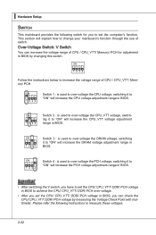
.... This section will increase the DRAM voltage adjustment range in BIOS, you to increase the voltage range of CPU / CPU_VTT/ Memory/ PCH for you can increase the voltage range of CPU / CPU_VTT/ Memory/ PCH. Switch 2 : is used to over -voltage the CPU voltage, switching it to "ON" will explain how to change...
.... This section will increase the DRAM voltage adjustment range in BIOS, you to increase the voltage range of CPU / CPU_VTT/ Memory/ PCH for you can increase the voltage range of CPU / CPU_VTT/ Memory/ PCH. Switch 2 : is used to over -voltage the CPU voltage, switching it to "ON" will explain how to change...

User Guide
Page 48
... Option ROM (VGA and RAID option ROM) form BIOS to OS Loader (typically INT 19H). Initialize USB device and different devices. Pass control to memory. Initialize memory. Wait for ACPI (Advanced Configuration and Power Interface).Prepare give control to get more information about the Debug LED message. Early CPU Initialize. Initialize chipset...
... Option ROM (VGA and RAID option ROM) form BIOS to OS Loader (typically INT 19H). Initialize USB device and different devices. Pass control to memory. Initialize memory. Wait for ACPI (Advanced Configuration and Power Interface).Prepare give control to get more information about the Debug LED message. Early CPU Initialize. Initialize chipset...
User Guide
Page 50
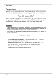
... held for better system performance. Important • The items under continuous update for reference only. • Upon boot-up, the 1st line appearing after the memory count is usually in this BIOS was released. 3-2 It is the BIOS version. When the message below appears on the computer and the system will...
... held for better system performance. Important • The items under continuous update for reference only. • Upon boot-up, the 1st line appearing after the memory count is usually in this BIOS was released. 3-2 It is the BIOS version. When the message below appears on the computer and the system will...

User Guide
Page 51
... the Exit menu or returns to the main menu from any menu by simply pressing . menu, and read the CPU information Enter the Memory-Z menu, and read the memory information Load Optimized Defaults Load Fail-Safe Defaults Save all the CMOS changes and exit Getting Help After entering the Setup menu, the...
... the Exit menu or returns to the main menu from any menu by simply pressing . menu, and read the CPU information Enter the Memory-Z menu, and read the memory information Load Optimized Defaults Load Fail-Safe Defaults Save all the CMOS changes and exit Getting Help After entering the Setup menu, the...

User Guide
Page 55
... stops when any detected error. ▶ System Information Press to the IDE/ SATA/ ESATA connector. This sub-menu shows the CPU information, BIOS version and memory status of the errors preset, it will halt on The setting determines whether the system will show the device information that you connect the HD...
... stops when any detected error. ▶ System Information Press to the IDE/ SATA/ ESATA connector. This sub-menu shows the CPU information, BIOS version and memory status of the errors preset, it will halt on The setting determines whether the system will show the device information that you connect the HD...

User Guide
Page 60
...sleep mode. ▶ ACPI Function This item is to save energy. In this section are : [S1] The S1 sleep mode is saved to main memory that remains powered while most other hardware components turn off to activate the ACPI (Advanced Configuration and Power Management Interface) Function. tem's context. [S3]..., such as Windows 2000/ XP, you can choose to restore the system when a "wake up" event occurs. 3-12 The information stored in memory will be used to enter the Standby mode in S1(POS) or S3(STR) fashion through the setting of system configuration and open applications/files...
...sleep mode. ▶ ACPI Function This item is to save energy. In this section are : [S1] The S1 sleep mode is saved to main memory that remains powered while most other hardware components turn off to activate the ACPI (Advanced Configuration and Power Management Interface) Function. tem's context. [S3]..., such as Windows 2000/ XP, you can choose to restore the system when a "wake up" event occurs. 3-12 The information stored in memory will be used to enter the Standby mode in S1(POS) or S3(STR) fashion through the setting of system configuration and open applications/files...

User Guide
Page 68
▍ BIOS Setup Cell Menu Important Change these settings only if you are familiar with the chipset. ▶ Current CPU / DRAM / QPI Frequency These items show the current frequencies of CPU, Memory and QPI. Read-only. 3-20
▍ BIOS Setup Cell Menu Important Change these settings only if you are familiar with the chipset. ▶ Current CPU / DRAM / QPI Frequency These items show the current frequencies of CPU, Memory and QPI. Read-only. 3-20

User Guide
Page 70
... Bit functionality can execute instructions simultaneously. This field will use only one core to execute the instructions. When a malicious worm attempts to insert code in memory by where application code can execute and where it enabled; • OS: An operating system that supports HT Technology. For further information please refer to...
... Bit functionality can execute instructions simultaneously. This field will use only one core to execute the instructions. When a malicious worm attempts to insert code in memory by where application code can execute and where it enabled; • OS: An operating system that supports HT Technology. For further information please refer to...

User Guide
Page 71
...This item is used to set the CPU Base clock (in MHz). It is used to enable/ disable the OC Genie function. ▶ Memory-Z Press to enable/ disable Intel Turbo Boost technology. The system will appear. This field will be enabled after you set the overclocking frequency in... "Adjust CPU Base Frequency (MHz)". The sub-menu displays the informations of installed memory. ▶ Current DRAM Channel1~4 Timing It shows the installed DRAM Timing. And the following screen appears. ▶ DIMM1~4 Memory SPD Information Press to set the initial base clock. This item is the Intel...
...This item is used to set the CPU Base clock (in MHz). It is used to enable/ disable the OC Genie function. ▶ Memory-Z Press to enable/ disable Intel Turbo Boost technology. The system will appear. This field will be enabled after you set the overclocking frequency in... "Adjust CPU Base Frequency (MHz)". The sub-menu displays the informations of installed memory. ▶ Current DRAM Channel1~4 Timing It shows the installed DRAM Timing. And the following screen appears. ▶ DIMM1~4 Memory SPD Information Press to set the initial base clock. This item is the Intel...

User Guide
Page 72
...DRAM timings and the following related "Advance DRAM Configuration" sub-menu manually. ▶ Advance DRAM Configuration When the DRAM Timing Mode is set to a memory cell. ▶ CH1/ CH2 tWR Minimum time interval between the end of write data burst and the start of different banks. 3-24 This item ... DRAM is installed in clock cycles) before DRAM refresh, refresh may be allowed to enter the sub-menu. ▶ CH1/ CH2 1T/2T Memory Timing This item controls the SDRAM command rate. ▍ BIOS Setup ▶ DRAM Timing Mode Select whether DRAM timing is controlled by BIOS based...
...DRAM timings and the following related "Advance DRAM Configuration" sub-menu manually. ▶ Advance DRAM Configuration When the DRAM Timing Mode is set to a memory cell. ▶ CH1/ CH2 tWR Minimum time interval between the end of write data burst and the start of different banks. 3-24 This item ... DRAM is installed in clock cycles) before DRAM refresh, refresh may be allowed to enter the sub-menu. ▶ CH1/ CH2 1T/2T Memory Timing This item controls the SDRAM command rate. ▍ BIOS Setup ▶ DRAM Timing Mode Select whether DRAM timing is controlled by BIOS based...
User Guide
Page 73
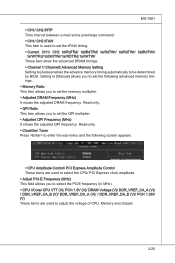
... Adjusted QPI Frequency (MHz) It shows the adjusted QPI frequency. Read-only. ▶ QPI Ratio This item allows you to set the memory multiplier. ▶ Adjusted DRAM Frequency (MHz) It shows the adjusted DRAM frequency. Setting to [Manual] allows you to set the tFAW .../ tdrRdTWr/ tddRdTWr/ tsrWrTRd/ tddWrTWr/ tsrRDTRd/ tsrWrTWr These item show the advanced DRAM timings. ▶ Channel 1/ Channel2 Advanced Memory Setting Setting to [Auto] enables the advance memory timing automatically to be determined by BIOS. MS-7581 ▶ CH1/ CH2 tRTP Time interval between a read and a precharge...
... Adjusted QPI Frequency (MHz) It shows the adjusted QPI frequency. Read-only. ▶ QPI Ratio This item allows you to set the memory multiplier. ▶ Adjusted DRAM Frequency (MHz) It shows the adjusted DRAM frequency. Setting to [Manual] allows you to set the tFAW .../ tdrRdTWr/ tddRdTWr/ tsrWrTRd/ tddWrTWr/ tsrRDTRd/ tsrWrTWr These item show the advanced DRAM timings. ▶ Channel 1/ Channel2 Advanced Memory Setting Setting to [Auto] enables the advance memory timing automatically to be determined by BIOS. MS-7581 ▶ CH1/ CH2 tRTP Time interval between a read and a precharge...

User Guide
Page 103
Appendix B Control Center Control Center, the most useful and powerful utility that MSI has spent much research and efforts to develop, helps users to monitor or configure the hardware status of MSI Mainboard in windows, such as CPU clock, voltage, fan speed and temperature. Before you install the Control Center, please make sure the system has meet the following requirements: 1. 256MB system memory. 2. B-B-1 Operation system: Windows XP or up. DVD-ROM drive for software installation. 3.
Appendix B Control Center Control Center, the most useful and powerful utility that MSI has spent much research and efforts to develop, helps users to monitor or configure the hardware status of MSI Mainboard in windows, such as CPU clock, voltage, fan speed and temperature. Before you install the Control Center, please make sure the system has meet the following requirements: 1. 256MB system memory. 2. B-B-1 Operation system: Windows XP or up. DVD-ROM drive for software installation. 3.

User Guide
Page 105
B-3 Mainboard Click Mainboard to select in this appendix are three options for you purchased. MS-7581 System Information There are for detailed information. Please refer to the appearance of mainboard, mainboard BIOS, audio, LAN and installed graphics card. Important The pictures in the System Information screen, you can read the information of your system for reference only and may vary from the product you to read the mainboard/ CPU/ memory information by clicking their respective name.
B-3 Mainboard Click Mainboard to select in this appendix are three options for you purchased. MS-7581 System Information There are for detailed information. Please refer to the appearance of mainboard, mainboard BIOS, audio, LAN and installed graphics card. Important The pictures in the System Information screen, you can read the information of your system for reference only and may vary from the product you to read the mainboard/ CPU/ memory information by clicking their respective name.

User Guide
Page 106
Memory Click Memory to select the DIMM slot. Click this arrow button to read the information of CPU. B-4 ▍ Control Center CPU Click CPU to read by clicking arrow button. You can select a DIMM slot you want to read the information of each memory DIMM slot.
Memory Click Memory to select the DIMM slot. Click this arrow button to read the information of CPU. B-4 ▍ Control Center CPU Click CPU to read by clicking arrow button. You can select a DIMM slot you want to read the information of each memory DIMM slot.

User Guide
Page 107
.../ Game) menus for different environments. B-5 Or you turn-off the system, the settings will be restored to the factory default. You can adjust the CPU/ memory parameters and the minimum fan speed separately for system to execute the configured setting.
.../ Game) menus for different environments. B-5 Or you turn-off the system, the settings will be restored to the factory default. You can adjust the CPU/ memory parameters and the minimum fan speed separately for system to execute the configured setting.


