
User Guide
Page 4
...determined by turning the equipment off and on a circuit different from that to which can radiate radio frequency energy and, if not installed and used in accordance with the emission limits. However, there is connected. ◯ Consult the dealer or an experienced radio/... operate the equipment. power cord, if any, must accept any interference received, including interference that interference will not occur in a residential installation. ▍ Preface FCC-B Radio Frequency Interference Statement This equipment has been tested and found to comply with Part 15 of the FCC ...
...determined by turning the equipment off and on a circuit different from that to which can radiate radio frequency energy and, if not installed and used in accordance with the emission limits. However, there is connected. ◯ Consult the dealer or an experienced radio/... operate the equipment. power cord, if any, must accept any interference received, including interference that interference will not occur in a residential installation. ▍ Preface FCC-B Radio Frequency Interference Statement This equipment has been tested and found to comply with Part 15 of the FCC ...
User Guide
Page 9
... Driver A-2 Software Configuration A-4 Hardware Setup A-19 Appendix B Control Center B-1 Activating Control Center B-2 System Information B-3 Overclocking B-5 Green Power B-7 Appendix C Intel SATA RAID C-1 Introduction C-2 BIOS Configuration C-3 Installing Driver C-10 Installing Software C-12 RAID Migration Instructions C-16 Recovery Volume Creation C-23 Degraded RAID Array C-26 Appendix D JMicron 322 RAID Drive Booster Manager D-1 Introduction D-2 RAID Configuration...
... Driver A-2 Software Configuration A-4 Hardware Setup A-19 Appendix B Control Center B-1 Activating Control Center B-2 System Information B-3 Overclocking B-5 Green Power B-7 Appendix C Intel SATA RAID C-1 Introduction C-2 BIOS Configuration C-3 Installing Driver C-10 Installing Software C-12 RAID Migration Instructions C-16 Recovery Volume Creation C-23 Degraded RAID Array C-26 Appendix D JMicron 322 RAID Drive Booster Manager D-1 Introduction D-2 RAID Configuration...
User Guide
Page 13
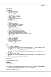
... - the PCI_E5 supports up to x8/ x8 - if you could search the product web page and find details on our web address below http://www.msi.com/index.php 1-3 MS-7581 Connectors ■ Back panel - 1 PS/2 keyboard port - 1 PS/2 mouse port - 1 Coaxial S/PDIF-out port - 1 Optical S/PDIF-out port...9632; 3 PCI Express 2.0 x16 slots - all PCIE x1 slots will unavailable when an expansion card was installed into PCI_ E5 slot. ■ 2 PCI slots, support 3.3V/ 5V PCI bus Interface Form Factor ■ ATX (30.5cm X 24.4 cm) Mounting ■ 9 mounting holes If you need to purchase accessories and ...
... - the PCI_E5 supports up to x8/ x8 - if you could search the product web page and find details on our web address below http://www.msi.com/index.php 1-3 MS-7581 Connectors ■ Back panel - 1 PS/2 keyboard port - 1 PS/2 mouse port - 1 Coaxial S/PDIF-out port - 1 Optical S/PDIF-out port...9632; 3 PCI Express 2.0 x16 slots - all PCIE x1 slots will unavailable when an expansion card was installed into PCI_ E5 slot. ■ 2 PCI slots, support 3.3V/ 5V PCI bus Interface Form Factor ■ ATX (30.5cm X 24.4 cm) Mounting ■ 9 mounting holes If you need to purchase accessories and ...

User Guide
Page 17
Static electricity may damage the components. 2-2-1 While doing the installation, be careful in the wrong orientation, the components will not work properly. For some components, if you with the information about hardware setup procedures. Use a grounded wrist strap before handling computer components. Chapter 2 Hardware Setup This chapter provides you install in holding the components and follow the installation procedures.
Static electricity may damage the components. 2-2-1 While doing the installation, be careful in the wrong orientation, the components will not work properly. For some components, if you with the information about hardware setup procedures. Use a grounded wrist strap before handling computer components. Chapter 2 Hardware Setup This chapter provides you install in holding the components and follow the installation procedures.
User Guide
Page 19
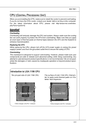
...cooling fan can work properly to apply some thermal paste on the computer. Replacing the CPU While replacing the CPU, always turn off the ATX power supply or unplug the power supply's power cord from overheating. The surface of LGA 1156 CPU. Overclocking This mainboard is designed to... install the cooler to operate beyond product specifications. Introduction to LGA 1156 CPU The pin-pad side of LGA 1156 CPU. Alignment Key Yellow triangle is the Pin 1 indicator Alignment Key Yellow triangle is the Pin 1 indicator 2-3 For the latest information about CPU, please visit http://www.msi....
...cooling fan can work properly to apply some thermal paste on the computer. Replacing the CPU While replacing the CPU, always turn off the ATX power supply or unplug the power supply's power cord from overheating. The surface of LGA 1156 CPU. Overclocking This mainboard is designed to... install the cooler to operate beyond product specifications. Introduction to LGA 1156 CPU The pin-pad side of LGA 1156 CPU. Alignment Key Yellow triangle is the Pin 1 indicator Alignment Key Yellow triangle is the Pin 1 indicator 2-3 For the latest information about CPU, please visit http://www.msi....

User Guide
Page 20
... CPU, make sure the CPU has a cooler attached on the top to apply some thermal paste on CPU before installing the heat sink/cooler fan for correct mating, put down the CPU in the socket housing frame. Open the load level. 2. After confirming the CPU ...direction for better heat dispersion. Alignment Key 2-4 The CPU socket has a plastic cap on the edge of your CPU & mainboard. 1. Wrong installation will cause the damage of the CPU base. Romove the cap (as the arrow shows). 4. Be sure to fully open position 3. Follow the steps below...
... CPU, make sure the CPU has a cooler attached on the top to apply some thermal paste on CPU before installing the heat sink/cooler fan for correct mating, put down the CPU in the socket housing frame. Open the load level. 2. After confirming the CPU ...direction for better heat dispersion. Alignment Key 2-4 The CPU socket has a plastic cap on the edge of your CPU & mainboard. 1. Wrong installation will cause the damage of the CPU base. Romove the cap (as the arrow shows). 4. Be sure to fully open position 3. Follow the steps below...

User Guide
Page 21
If not, take out the CPU with pure vertical motion and reinstall. 6. Visually inspect if the CPU is firmly installed before you install the cooler. Secure the lever near the hook end under the retention tab. 8. Engage the load lever while pressing down lightly onto the load plate. Make sure the four hooks are in porper position before turning on your CPU cooler is seated well into the socket. Alignment Key 7. Important • Confirm if your system. • Do not touch the CPU socket pins to avoid damaging. 2-5 MS-7581 5.
If not, take out the CPU with pure vertical motion and reinstall. 6. Visually inspect if the CPU is firmly installed before you install the cooler. Secure the lever near the hook end under the retention tab. 8. Engage the load lever while pressing down lightly onto the load plate. Make sure the four hooks are in porper position before turning on your CPU cooler is seated well into the socket. Alignment Key 7. Important • Confirm if your system. • Do not touch the CPU socket pins to avoid damaging. 2-5 MS-7581 5.
User Guide
Page 22
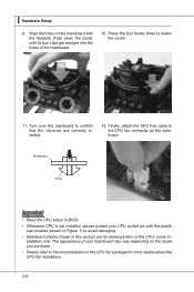
Align the holes on the mainboard. Mainboard Hook Important • Read the CPU status in BIOS. • Whenever CPU is not installed, always protect your mainboard may vary depending on the model you purchase. • Please refer to the CPU fan connector on the mainboard with the ... to confirm that the clip-ends are for demonstration of the CPU/ cooler in the CPU fan package for more details about the CPU fan installation. 2-6 Finally, attach the CPU Fan cable to the documentation in - stallation only.
Align the holes on the mainboard. Mainboard Hook Important • Read the CPU status in BIOS. • Whenever CPU is not installed, always protect your mainboard may vary depending on the model you purchase. • Please refer to the CPU fan connector on the mainboard with the ... to confirm that the clip-ends are for demonstration of the CPU/ cooler in the CPU fan package for more details about the CPU fan installation. 2-6 Finally, attach the CPU Fan cable to the documentation in - stallation only.

User Guide
Page 23
... Important • DDR3 memory modules are used for memory population rules. For more information on compatible components, please visit http://www.msi.com/index.php?func=testreport DDR3 240-pin, 1.5V 48x2=96 pin 72x2=144 pin Memory Population Rule Please refer to 15+GB... (not full 16GB) when each DIMM is not backwards compatible. The following illustrations for installing memory modules. Dual-Channel mode Population Rule In Dual-Channel mode, the memory modules can enhance the system performance. Enabling Dual-Channel mode can...
... Important • DDR3 memory modules are used for memory population rules. For more information on compatible components, please visit http://www.msi.com/index.php?func=testreport DDR3 240-pin, 1.5V 48x2=96 pin 72x2=144 pin Memory Population Rule Please refer to 15+GB... (not full 16GB) when each DIMM is not backwards compatible. The following illustrations for installing memory modules. Dual-Channel mode Population Rule In Dual-Channel mode, the memory modules can enhance the system performance. Enabling Dual-Channel mode can...

User Guide
Page 24
... one notch on the memory module is properly seated. 3. Manually check if the memory module has been locked in the DIMM slot. 2-8 ▍ Hardware Setup Installing Memory Modules 1.
... one notch on the memory module is properly seated. 3. Manually check if the memory module has been locked in the DIMM slot. 2-8 ▍ Hardware Setup Installing Memory Modules 1.

User Guide
Page 28
... K dk ldkddfkkakfskkdskkdakaddfdddffdfka-ddkdfdfldkddj adfdsdddjdfddf fkadadsf dddffdfadasfadfsddsddadasdsaddsdafsddadsdddfdsadddffffafsfsdafsdf ff df 3 1/2" Fl oppy Disk Dr i veConnector CD-RMOSMI Kdkldkddfkkakfskkdskkdakaddfdddffdfkadd-kdffdldkddjdafdsdddjdfddfdfkaadsfdddffdfadasfsadfddsddadasdsaddsdafsddadsdddfdsadddfffaffsfsdasfdfffdf 3 1/2" F loppy Di sk D r ive Connector Important If you install two IDE devices on the same cable, you must configure the drives separately to IDE device's documentation supplied by setting jumpers. Refer to master / slave...
... K dk ldkddfkkakfskkdskkdakaddfdddffdfka-ddkdfdfldkddj adfdsdddjdfddf fkadadsf dddffdfadasfadfsddsddadasdsaddsdafsddadsdddfdsadddffffafsfsdafsdf ff df 3 1/2" Fl oppy Disk Dr i veConnector CD-RMOSMI Kdkldkddfkkakfskkdskkdakaddfdddffdfkadd-kdffdldkddjdafdsdddjdfddfdfkaadsfdddffdfadasfsadfddsddadasdsaddsdafsddadsdddfdsadddfffaffsfsdasfdfffdf 3 1/2" F loppy Di sk D r ive Connector Important If you install two IDE devices on the same cable, you must configure the drives separately to IDE device's documentation supplied by setting jumpers. Refer to master / slave...

User Guide
Page 30
... 3.S2.e+1n1.sG2orVround Important • Please refer to the recommended CPU fans at processor's official website or consult the vendors for CPUFAN. 2-14 You can install Control Center utility that the red wire is Ground and should be connected to GND. the black wire is the positive and should be connected...
... 3.S2.e+1n1.sG2orVround Important • Please refer to the recommended CPU fans at processor's official website or consult the vendors for CPUFAN. 2-14 You can install Control Center utility that the red wire is Ground and should be connected to GND. the black wire is the positive and should be connected...

User Guide
Page 36
...this button to clear CMOS data in BIOS for future using. 2-20 OC Genie Button: OC Genie This button is in BIOS setup. Important Please install the DDR3 1333 and up memory and equip better heat sink/ cooler with OC Genie function. And we suggest you want to clear the system... not guarantee the OC Genie overclocking range and the damages or risks caused by the OC Genie overclocking behavior. Press the button to change your motherboard's function through the use the button to overclocking profile in power off (G3) state, the system will explain how to clear the data. This ...
...this button to clear CMOS data in BIOS for future using. 2-20 OC Genie Button: OC Genie This button is in BIOS setup. Important Please install the DDR3 1333 and up memory and equip better heat sink/ cooler with OC Genie function. And we suggest you want to clear the system... not guarantee the OC Genie overclocking range and the damages or risks caused by the OC Genie overclocking behavior. Press the button to change your motherboard's function through the use the button to overclocking profile in power off (G3) state, the system will explain how to clear the data. This ...

User Guide
Page 40
▍ Hardware Setup Slots PCIE (Peripheral Component Interconnect Express) Slot The PCI Express slot supports the PCI Express interface expansion card. PCI Express x16 Slot PCI Express x1 Slot Important When adding or removing expansion cards, make sure that you unplug the power supply first. Meanwhile, read the documentation for the expansion card to configure any necessary hardware or software settings for the expansion card, such as jumpers, switches or BIOS configuration. The PCI Express x1 slots will unavailable when an expansion card was installed into PCI_E5 slot. 2-24
▍ Hardware Setup Slots PCIE (Peripheral Component Interconnect Express) Slot The PCI Express slot supports the PCI Express interface expansion card. PCI Express x16 Slot PCI Express x1 Slot Important When adding or removing expansion cards, make sure that you unplug the power supply first. Meanwhile, read the documentation for the expansion card to configure any necessary hardware or software settings for the expansion card, such as jumpers, switches or BIOS configuration. The PCI Express x1 slots will unavailable when an expansion card was installed into PCI_E5 slot. 2-24
User Guide
Page 41
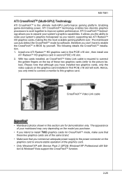
...it, supporting two ATI RadeonTM HD graphics cards, making this the most scalable gaming platform ever. The following details the CrossFireXTM installation. 1. It allows you the ability to enable the CrossFireXTM in this graphics card. CrossFireXTM Video Link cable Important • Mainboard...operation of the same brand. • Make sure that although you to expand your system's graphics horsepower as you intend to install TWO graphics cards for demonstration only. ATI CrossFireXTM technology allows you have to scale your system's graphics capabilities. MS-7581 ATI CrossFireXTM...
...it, supporting two ATI RadeonTM HD graphics cards, making this the most scalable gaming platform ever. The following details the CrossFireXTM installation. 1. It allows you the ability to enable the CrossFireXTM in this graphics card. CrossFireXTM Video Link cable Important • Mainboard...operation of the same brand. • Make sure that although you to expand your system's graphics horsepower as you intend to install TWO graphics cards for demonstration only. ATI CrossFireXTM technology allows you have to scale your system's graphics capabilities. MS-7581 ATI CrossFireXTM...

User Guide
Page 42
for CrossFireXTM to operate. When all of the hardware and software has been properly set up and installed, reboot the system. Important A CrossFireXTM system has four possible display modes: • SuperTiling • Scissor Mode • Alternate Frame Rendering • Super Anti-aliasing. The ...
for CrossFireXTM to operate. When all of the hardware and software has been properly set up and installed, reboot the system. Important A CrossFireXTM system has four possible display modes: • SuperTiling • Scissor Mode • Alternate Frame Rendering • Super Anti-aliasing. The ...

User Guide
Page 43
... for better graphics performance, please refer to the first PCI Express card. Hence, you only need to connect a monitor to the following instructions. 1. Install two graphics cards on the first card will work. To utilize this section are of the same brand and specifications. • Make sure that you...on the graphics card to ensure stable operation of your mainboard may vary depending on the model you purchase. • If you intend to install TWO x16 graphics cards, make sure that although you intend to use the SLI mode for demonstration only. SLI Video Link Card If you ...
... for better graphics performance, please refer to the first PCI Express card. Hence, you only need to connect a monitor to the following instructions. 1. Install two graphics cards on the first card will work. To utilize this section are of the same brand and specifications. • Make sure that you...on the graphics card to ensure stable operation of your mainboard may vary depending on the model you purchase. • If you intend to install TWO x16 graphics cards, make sure that although you intend to use the SLI mode for demonstration only. SLI Video Link Card If you ...

User Guide
Page 44
Check the box 3. ▍ Hardware Setup 2. After the hardware installation is disabled. 2-28 A configuration panel will show in the system tray confirming the Multi-GPU has been enabled. Important If you want to your system ...-GPU settings, please refer to remove one graphics card and quit the SLI function, make sure the "MultiGPU" function is completed, restart the system and install the NV SLI driver/utility. Check the Enable multi-GPU box to enable the SLI function for Multi-GPU control. Restart your graphics card manual).
Check the box 3. ▍ Hardware Setup 2. After the hardware installation is disabled. 2-28 A configuration panel will show in the system tray confirming the Multi-GPU has been enabled. Important If you want to your system ...-GPU settings, please refer to remove one graphics card and quit the SLI function, make sure the "MultiGPU" function is completed, restart the system and install the NV SLI driver/utility. Check the Enable multi-GPU box to enable the SLI function for Multi-GPU control. Restart your graphics card manual).

User Guide
Page 69
... Read only. ▶ CPU Feature Press to set the performance level of the processor during idle. This submenu shows the information of installed CPU. ▶ CPU Technology Support Press to enter the sub-menu and the following screen appears: ▶ Intel EIST The Enhanced Intel...supports c-state technology. ▶ C1E Support To enable this sub-menu, it shows the installed CPU technologies. Not all processors support Enhanced Halt state (C1E). 3-21 This field will appear after you installed the CPU which supports speedstep technology. ▶ Intel C-STATE C-state is a power ...
... Read only. ▶ CPU Feature Press to set the performance level of the processor during idle. This submenu shows the information of installed CPU. ▶ CPU Technology Support Press to enter the sub-menu and the following screen appears: ▶ Intel EIST The Enhanced Intel...supports c-state technology. ▶ C1E Support To enable this sub-menu, it shows the installed CPU technologies. Not all processors support Enhanced Halt state (C1E). 3-21 This field will appear after you installed the CPU which supports speedstep technology. ▶ Intel C-STATE C-state is a power ...

User Guide
Page 70
... Hyper-Threading Technology for CPU to run the overclocking frequency (base clock * turbo ratio) absolutely. ▶ Intel EIST The Enhanced Intel SpeedStep technology allows you installed the CPU which supports speedstep technology. ▶ C1E Support To enable this item if your computer system requires ALL of the processor to enable/disable...
... Hyper-Threading Technology for CPU to run the overclocking frequency (base clock * turbo ratio) absolutely. ▶ Intel EIST The Enhanced Intel SpeedStep technology allows you installed the CPU which supports speedstep technology. ▶ C1E Support To enable this item if your computer system requires ALL of the processor to enable/disable...


