User Guide
Page 8
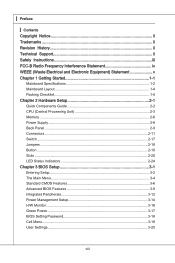
... iii FCC-B Radio Frequency Interference Statement iv WEEE (Waste Electrical and Electronic Equipment) Statement v Chapter 1 Getting Started 1-1 Mainboard Specifications 1-2 Mainboard Layout 1-4 Packing Checklist 1-5 Chapter 2 Hardware Setup 2-1 Quick Components Guide 2-2 CPU (Central Processing Unit 2-3 Memory 2-6 Power Supply 2-8 Back Panel 2-9 Connectors 2-11 Switch 2-17 Jumpers 2-18 Button 2-19 Slots 2-20 LED Status Indicators...
... iii FCC-B Radio Frequency Interference Statement iv WEEE (Waste Electrical and Electronic Equipment) Statement v Chapter 1 Getting Started 1-1 Mainboard Specifications 1-2 Mainboard Layout 1-4 Packing Checklist 1-5 Chapter 2 Hardware Setup 2-1 Quick Components Guide 2-2 CPU (Central Processing Unit 2-3 Memory 2-6 Power Supply 2-8 Back Panel 2-9 Connectors 2-11 Switch 2-17 Jumpers 2-18 Button 2-19 Slots 2-20 LED Status Indicators...
User Guide
Page 9
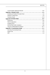
MS-7578 Load Fail-Safe/ Optimized Defaults 3-27 Appendix A Realtek Audio A-1 Installing the Realtek HD Audio Driver A-2 Software Configuration A-4 Hardware Setup A-19 Appendix B NVIDIA RAID B-1 Introduction B-2 RAID Configuration B-3 Installing Driver B-7 NVIDIA RAID Utility Installation B-8 Using the NVMediaShield Software B-11 Appendix C Overclocking Center C-1 Activating Overclocking Center C-2 System Info C-3 DOT C-5 ix
MS-7578 Load Fail-Safe/ Optimized Defaults 3-27 Appendix A Realtek Audio A-1 Installing the Realtek HD Audio Driver A-2 Software Configuration A-4 Hardware Setup A-19 Appendix B NVIDIA RAID B-1 Introduction B-2 RAID Configuration B-3 Installing Driver B-7 NVIDIA RAID Utility Installation B-8 Using the NVMediaShield Software B-11 Appendix C Overclocking Center C-1 Activating Overclocking Center C-2 System Info C-3 DOT C-5 ix

User Guide
Page 17
For some components, if you with the information about hardware setup procedures. Use a grounded wrist strap before handling computer components. Static electricity may damage the components. 2-2-1 While doing the installation, be careful in the wrong orientation, the components will not work properly. Chapter 2 Hardware Setup This chapter provides you install in holding the components and follow the installation procedures.
For some components, if you with the information about hardware setup procedures. Use a grounded wrist strap before handling computer components. Static electricity may damage the components. 2-2-1 While doing the installation, be careful in the wrong orientation, the components will not work properly. Chapter 2 Hardware Setup This chapter provides you install in holding the components and follow the installation procedures.

User Guide
Page 20
... pins should point as shown in the correct orientation. 3. Wrong installation will cause the damage of the CPU. Look for better heat dispersion. ▍ Hardware Setup CPU & Cooler Installation When you are installing the CPU, make sure the CPU is properly and completely embedded into the socket and close the lever...
... pins should point as shown in the correct orientation. 3. Wrong installation will cause the damage of the CPU. Look for better heat dispersion. ▍ Hardware Setup CPU & Cooler Installation When you are installing the CPU, make sure the CPU is properly and completely embedded into the socket and close the lever...
User Guide
Page 22
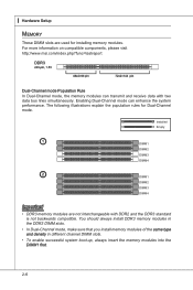
...; To enable successful system boot-up, always insert the memory modules into the DIMM1 first. 2-6 For more information on compatible components, please visit http://www.msi.com/index.php?func=testreport DDR3 240-pin, 1.5V 48x2=96 pin 72x2=144 pin Dual-Channel mode Population Rule In Dual-Channel mode, the... for Dual-Channel mode. Enabling Dual-Channel mode can transmit and receive data with DDR2 and the DDR3 standard is not backwards compatible. ▍ Hardware Setup Memory These DIMM slots are not interchangeable with two data bus lines simultaneously.
...; To enable successful system boot-up, always insert the memory modules into the DIMM1 first. 2-6 For more information on compatible components, please visit http://www.msi.com/index.php?func=testreport DDR3 240-pin, 1.5V 48x2=96 pin 72x2=144 pin Dual-Channel mode Population Rule In Dual-Channel mode, the... for Dual-Channel mode. Enabling Dual-Channel mode can transmit and receive data with DDR2 and the DDR3 standard is not backwards compatible. ▍ Hardware Setup Memory These DIMM slots are not interchangeable with two data bus lines simultaneously.
User Guide
Page 24
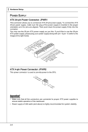
...9613; Hardware Setup Power Supply ATX 24-pin Power Connector: JPWR1 This connector allows you to the image at the right hand). 1.+23.+3.33.G4V.3.r+5Vo.5uG6Vn.r7+do.5uG8Vn.rP9do.Wu51nV0R1d.S1+O1B.1+K2211.V+3213.V+4.133.-5V.113.2G6V1V.rP7o1.SuG81-n.rO9Gdo2.NurG0o2n#.ruR1do2n.eu+2ds2n5.+3dV2.5+4V5.GVround ATX 4-pin Power .... If you like to the CPU. 2.G1.rGouronudnd 4.+31.+21V2V Important • Make sure that all the connectors are aligned. To connect the ATX 24-pin power supply, make sure the plug of the power supply is inserted in the proper orientation and the pins are connected to proper...
...9613; Hardware Setup Power Supply ATX 24-pin Power Connector: JPWR1 This connector allows you to the image at the right hand). 1.+23.+3.33.G4V.3.r+5Vo.5uG6Vn.r7+do.5uG8Vn.rP9do.Wu51nV0R1d.S1+O1B.1+K2211.V+3213.V+4.133.-5V.113.2G6V1V.rP7o1.SuG81-n.rO9Gdo2.NurG0o2n#.ruR1do2n.eu+2ds2n5.+3dV2.5+4V5.GVround ATX 4-pin Power .... If you like to the CPU. 2.G1.rGouronudnd 4.+31.+21V2V Important • Make sure that all the connectors are aligned. To connect the ATX 24-pin power supply, make sure the plug of the power supply is inserted in the proper orientation and the pins are connected to proper...

User Guide
Page 26
... in 5.1/ 7.1 channel mode. ■ SS-Out (Gray) - Side-Surround Out 7.1 channel mode. 2-10 Line In, is a connector for microphones. ■ RS-Out (Black) - ▍ Hardware Setup ▶ Audio Ports These audio connectors are used for external CD player, tape-player or other audio devices. ■ Line-Out (Green) - Mic, is used...
... in 5.1/ 7.1 channel mode. ■ SS-Out (Gray) - Side-Surround Out 7.1 channel mode. 2-10 Line In, is a connector for microphones. ■ RS-Out (Black) - ▍ Hardware Setup ▶ Audio Ports These audio connectors are used for external CD player, tape-player or other audio devices. ■ Line-Out (Green) - Mic, is used...

User Guide
Page 28
....RDReLseEesDrevteSdwitch SpeakeBr2uz.z-e4r.+6.-8.+ JFP2 1.G3.rSo5uu.Psn7opd.NweonedrPLLinEEDD 2-12 Front Panel Connector: JFP1, JFP2 This connector is a high-speed Serial ATA interface port. ▍ Hardware Setup Serial ATA Connector: SATA1~5 This connector is for electrical connection to one Serial ATA device. The JFP1 is compliant with Intel® Front Panel I/O Connectivity...
....RDReLseEesDrevteSdwitch SpeakeBr2uz.z-e4r.+6.-8.+ JFP2 1.G3.rSo5uu.Psn7opd.NweonedrPLLinEEDD 2-12 Front Panel Connector: JFP1, JFP2 This connector is a high-speed Serial ATA interface port. ▍ Hardware Setup Serial ATA Connector: SATA1~5 This connector is for electrical connection to one Serial ATA device. The JFP1 is compliant with Intel® Front Panel I/O Connectivity...

User Guide
Page 30
....DG9B-.rNDoo+unPdin USB 2.0 Bracket (optional) Important Note that the pins of VCC and GND must be connected correctly to avoid possible damage. ▍ Hardware Setup Front USB Connector: JUSB1/ JUSB2/ JUSB3 This connector, compliant with Intel® I/O Connectivity Design Guide, is compliant with Intel® Front Panel I/O Connectivity Design Guide...
....DG9B-.rNDoo+unPdin USB 2.0 Bracket (optional) Important Note that the pins of VCC and GND must be connected correctly to avoid possible damage. ▍ Hardware Setup Front USB Connector: JUSB1/ JUSB2/ JUSB3 This connector, compliant with Intel® I/O Connectivity Design Guide, is compliant with Intel® Front Panel I/O Connectivity Design Guide...

User Guide
Page 32
▍ Hardware Setup Serial Port Connector: JCOM1 This connector is a 16550A high speed communication port that sends/receives 16 bytes FIFOs. You can attach a serial device. 2.S4I.ND6T.DR8S1.C0RT.NSo Pin 1.D3.CS5DO.G7Ur.RTo9uT.RnSdI 2-16
▍ Hardware Setup Serial Port Connector: JCOM1 This connector is a 16550A high speed communication port that sends/receives 16 bytes FIFOs. You can attach a serial device. 2.S4I.ND6T.DR8S1.C0RT.NSo Pin 1.D3.CS5DO.G7Ur.RTo9uT.RnSdI 2-16
User Guide
Page 34
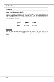
it is on . Then return to clear data. 1 JBAT1 1 Keep Data 1 Clear Data Important You can automatically boot OS every time it will damage the mainboard. 2-18 With the CMOS RAM, the system can clear CMOS by shorting 2-3 pin while the system is a CMOS RAM onboard that has a power supply from an external battery to keep the data of system configuration. Avoid clearing the CMOS while the system is turned on ; If you want to clear the system configuration, set the jumper to 1-2 pin position. ▍ Hardware Setup Jumpers Clear CMOS Jumper: JBAT1 There is off.
it is on . Then return to clear data. 1 JBAT1 1 Keep Data 1 Clear Data Important You can automatically boot OS every time it will damage the mainboard. 2-18 With the CMOS RAM, the system can clear CMOS by shorting 2-3 pin while the system is a CMOS RAM onboard that has a power supply from an external battery to keep the data of system configuration. Avoid clearing the CMOS while the system is turned on ; If you want to clear the system configuration, set the jumper to 1-2 pin position. ▍ Hardware Setup Jumpers Clear CMOS Jumper: JBAT1 There is off.
User Guide
Page 36
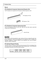
... The IRQ, acronym of interrupt request line and pronounced I-R-Q, are typically connected to the PCI bus pins as jumpers, switches or BIOS configuration. ▍ Hardware Setup Slots PCI (Peripheral Component Interconnect) Express Slot The PCI Express slot supports the PCI Express interface expansion card. PCI Express x16 Slot PCI Express x1...
... The IRQ, acronym of interrupt request line and pronounced I-R-Q, are typically connected to the PCI bus pins as jumpers, switches or BIOS configuration. ▍ Hardware Setup Slots PCI (Peripheral Component Interconnect) Express Slot The PCI Express slot supports the PCI Express interface expansion card. PCI Express x16 Slot PCI Express x1...

User Guide
Page 38
... Check the Enable multi-GPU box to enable the SLI function for Multi-GPU control. Restart your graphics card manual). Check the box 3. ▍ Hardware Setup 2. Important If you want to your system and a pop-up message will show in the system tray confirming the Multi-GPU has been enabled. A configuration...
... Check the Enable multi-GPU box to enable the SLI function for Multi-GPU control. Restart your graphics card manual). Check the box 3. ▍ Hardware Setup 2. Important If you want to your system and a pop-up message will show in the system tray confirming the Multi-GPU has been enabled. A configuration...

User Guide
Page 40
Follow the instructions below to read. : ON, : OFF 4 of the LEDs will light blue when CPU is in 4 phase power mode. 1 of the LEDs will light blue when CPU is in 1 phase power mode. 2-24 ▍ Hardware Setup LED Status Indicators APS LEDs ON 12 APS LEDs These APS (Active Phase Switching) LEDs indicate the current CPU power phase mode.
Follow the instructions below to read. : ON, : OFF 4 of the LEDs will light blue when CPU is in 4 phase power mode. 1 of the LEDs will light blue when CPU is in 1 phase power mode. 2-24 ▍ Hardware Setup LED Status Indicators APS LEDs ON 12 APS LEDs These APS (Active Phase Switching) LEDs indicate the current CPU power phase mode.

User Guide
Page 41
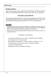
Chapter 3 BIOS Setup This chapter provides information on the BIOS Setup program and allows you to run the Setup program when: ■ An error message appears on the screen during the system booting up, and requests you to change the default settings for optimum use. You may need to run SETUP. ■ You want to configure the system for customized features. 2-3-1
Chapter 3 BIOS Setup This chapter provides information on the BIOS Setup program and allows you to run the Setup program when: ■ An error message appears on the screen during the system booting up, and requests you to change the default settings for optimum use. You may need to run SETUP. ■ You want to configure the system for customized features. 2-3-1
User Guide
Page 42
... (Power On Self Test) process. V1.0 refers to the BIOS version. 060909 refers to enter Setup, restart the system by simultaneously pressing , , and keys. Press DEL to enter SETUP If the message disappears before you respond and you still wish to the date this chapter are under...number. 6th digit refers to the chipset as I = Intel, N = NVIDIA, A = AMD and V = VIA. 7th - 8th digit refers to enter Setup. ▍ BIOS Setup Entering Setup Power on the screen, press key to the customer as MS = all standard customers. Important • The items under continuous update for reference only...
... (Power On Self Test) process. V1.0 refers to the BIOS version. 060909 refers to enter Setup, restart the system by simultaneously pressing , , and keys. Press DEL to enter SETUP If the message disappears before you respond and you still wish to the date this chapter are under...number. 6th digit refers to the chipset as I = Intel, N = NVIDIA, A = AMD and V = VIA. 7th - 8th digit refers to enter Setup. ▍ BIOS Setup Entering Setup Power on the screen, press key to the customer as MS = all standard customers. Important • The items under continuous update for reference only...
User Guide
Page 43
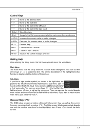
...to highlight the field and press to call up the sub-menu. You can call up this field. Main Menu The main menu lists the setup functions you can use and the possible selections for a field parameter. The Help screen lists the appropriate keys to use the control keys to ...to the main menu, just press the . You can use the arrow keys ( ↑↓ ) to select the item. General Help The BIOS setup program provides a General Help screen. A sub-menu contains additional options for the highlighted item. MS-7578 Control Keys Move to the previous item Move to...
...to highlight the field and press to call up the sub-menu. You can call up this field. Main Menu The main menu lists the setup functions you can use and the possible selections for a field parameter. The Help screen lists the appropriate keys to use the control keys to ...to the main menu, just press the . You can use the arrow keys ( ↑↓ ) to select the item. General Help The BIOS setup program provides a General Help screen. A sub-menu contains additional options for the highlighted item. MS-7578 Control Keys Move to the previous item Move to...

User Guide
Page 44
... Features Use this menu for basic system configurations, such as time, date etc. ▶ Advanced BIOS Features Use this menu to setup the items of the BIOS special enhanced features. ▶ Integrated Peripherals Use this menu to specify your settings for integrated peripherals. ▶ ...Power Management Setup Use this menu to specify your settings for power management. ▶ H/W Monitor This entry shows your PC health status. ▶ Green...
... Features Use this menu for basic system configurations, such as time, date etc. ▶ Advanced BIOS Features Use this menu to setup the items of the BIOS special enhanced features. ▶ Integrated Peripherals Use this menu to specify your settings for integrated peripherals. ▶ ...Power Management Setup Use this menu to specify your settings for power management. ▶ H/W Monitor This entry shows your PC health status. ▶ Green...

User Guide
Page 45
MS-7578 ▶ Load Fail-Safe Defaults Use this menu to load the default values set by the BIOS vendor for stable system performance. ▶ Load Optimized Defaults Use this menu to load the default values set by the mainboard manufacturer specifically for optimal performance of the mainboard. ▶ Save & Exit Setup Save changes to CMOS and exit setup. ▶ Exit Without Saving Abandon all changes and exit setup. 3-5
MS-7578 ▶ Load Fail-Safe Defaults Use this menu to load the default values set by the BIOS vendor for stable system performance. ▶ Load Optimized Defaults Use this menu to load the default values set by the mainboard manufacturer specifically for optimal performance of the mainboard. ▶ Save & Exit Setup Save changes to CMOS and exit setup. ▶ Exit Without Saving Abandon all changes and exit setup. 3-5

User Guide
Page 46
... year can be adjusted by BIOS. through Dec. [date] The date from Jan. The format is . 3-6 ▍ BIOS Setup Standard CMOS Features The items in Standard CMOS Features Menu include some basic setup items. Use the arrow keys to highlight the item and then use the or keys to select the value...
... year can be adjusted by BIOS. through Dec. [date] The date from Jan. The format is . 3-6 ▍ BIOS Setup Standard CMOS Features The items in Standard CMOS Features Menu include some basic setup items. Use the arrow keys to highlight the item and then use the or keys to select the value...

