User Guide
Page 5
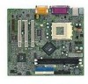
Hardware Setup 2-1 Central Processing Unit: CPU 2-2 CPU Installation Procedures 2-2 CPU Core Speed Derivation Procedure 2-4 CPU Clock Selection 2-4 Memory 2-5 Introduction to SDRAM 2-5 DIMM Module Combination 2-6 Installing DIMM Modules 2-6 Power Supply 2-7 ATX 20-Pin Power Connector: JPWR1 2-7 Back Panel 2-8 Mouse Connector 2-8 Keyboard Connector 2-9 USB Connectors 2-9 Serial Port Connector: COM A 2-10 VGA DB 15 Pin Connector 2-10 Parallel ...
Hardware Setup 2-1 Central Processing Unit: CPU 2-2 CPU Installation Procedures 2-2 CPU Core Speed Derivation Procedure 2-4 CPU Clock Selection 2-4 Memory 2-5 Introduction to SDRAM 2-5 DIMM Module Combination 2-6 Installing DIMM Modules 2-6 Power Supply 2-7 ATX 20-Pin Power Connector: JPWR1 2-7 Back Panel 2-8 Mouse Connector 2-8 Keyboard Connector 2-9 USB Connectors 2-9 Serial Port Connector: COM A 2-10 VGA DB 15 Pin Connector 2-10 Parallel ...
User Guide
Page 6
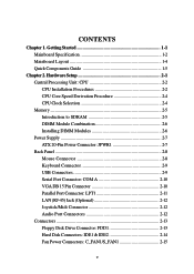
... Chassis Intrusion Switch Connector: JCASE1 2-19 Wake On Ring Connector: JMDM1 2-20 Wake On LAN Connector: JWOL1 2-20 Jumpers 2-21 Clear CMOS Jumper: JBAT1 2-21 CPU Clock Selection Jumper: JFSB1 2-22 Slots 2-23 PCI Slots 2-23 CNR (Communication Network Riser) Slot 2-23 ISA Slot (Optional 2-23 PCI Interrupt Request Routing 2-24...
... Chassis Intrusion Switch Connector: JCASE1 2-19 Wake On Ring Connector: JMDM1 2-20 Wake On LAN Connector: JWOL1 2-20 Jumpers 2-21 Clear CMOS Jumper: JBAT1 2-21 CPU Clock Selection Jumper: JFSB1 2-22 Slots 2-23 PCI Slots 2-23 CNR (Communication Network Riser) Slot 2-23 ISA Slot (Optional 2-23 PCI Interrupt Request Routing 2-24...
User Guide
Page 9
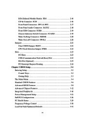
... Master and Ultra DMA 33/66/100 operation modes Can connect up to four IDE devices 1-2 PCI advanced high performance memory controller - Chapter 1 Mainboard Specification CPU Supports Socket 462 for AMD® Duron™/Athlon™ /Athlon™ XP processors Supports Athlon XP 1900+ MHz and higher processor Chipset VIA®...
... Master and Ultra DMA 33/66/100 operation modes Can connect up to four IDE devices 1-2 PCI advanced high performance memory controller - Chapter 1 Mainboard Specification CPU Supports Socket 462 for AMD® Duron™/Athlon™ /Athlon™ XP processors Supports Athlon XP 1900+ MHz and higher processor Chipset VIA®...
User Guide
Page 12
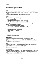
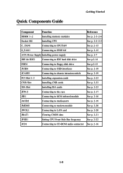
Quick Components Guide Getting Started Component Function DIMM 1~2 Installing memory modules Socket 462 Installing CPU C_FAN1 Connecting to CPUFAN S_FAN1 Connecting to SYSFAN ATX Power Supply Installing power supply IDE1& IDE2 Connecting to IDE hard disk drive FDD1 Connecting... to IrDA infrared module JAUD2 Connecting to Audio ports JMDM1 Connecting to modem module JWOL1 Connecting to LAN card JBAT1 Clearing CMOS data JFSB1 Setting CPU Front Side Bus frequency JCD1 Connecting to CD-ROM audio connector Reference See p. 2-5~2-6 See p. 2-2~2-3 See p. 2-15 See p. 2-15 ...
Quick Components Guide Getting Started Component Function DIMM 1~2 Installing memory modules Socket 462 Installing CPU C_FAN1 Connecting to CPUFAN S_FAN1 Connecting to SYSFAN ATX Power Supply Installing power supply IDE1& IDE2 Connecting to IDE hard disk drive FDD1 Connecting... to IrDA infrared module JAUD2 Connecting to Audio ports JMDM1 Connecting to modem module JWOL1 Connecting to LAN card JBAT1 Clearing CMOS data JFSB1 Setting CPU Front Side Bus frequency JCD1 Connecting to CD-ROM audio connector Reference See p. 2-5~2-6 See p. 2-2~2-3 See p. 2-15 See p. 2-15 ...
User Guide
Page 13
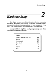
... damage the components. Hardware Setup Hardware Setup This chapter provides you install in holding the components and follow the installation procedures. TOPICS Central Processing Unit: CPU 2-2 Memory 2-5 Power Supply 2-7 Back Panel 2-8 Connectors 2-13 Jumpers 2-21 Slots 2-23 2-1
... damage the components. Hardware Setup Hardware Setup This chapter provides you install in holding the components and follow the installation procedures. TOPICS Central Processing Unit: CPU 2-2 Memory 2-5 Power Supply 2-7 Back Panel 2-8 Connectors 2-13 Jumpers 2-21 Slots 2-23 2-1
User Guide
Page 14
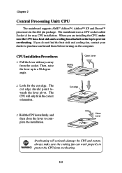
...contact your dealer to purchase and install them before turning on the top to a 90-degree angle. Look for easy CPU installation. Hold the CPU down firmly, and Close Lever then close the lever to WARNING! Overheating will only fit in the 462 pin package. ...plete the installation. protect the CPU from the socket. Sliding Plate Open Lever 2. The CPU will seriously damage the CPU and system, always make sure the CPU has a heat sink and a cooling fan attached on the computer. CPU Installation Procedures 1. The mainboard uses a CPU socket called Socket A for the...
...contact your dealer to purchase and install them before turning on the top to a 90-degree angle. Look for easy CPU installation. Hold the CPU down firmly, and Close Lever then close the lever to WARNING! Overheating will only fit in the 462 pin package. ...plete the installation. protect the CPU from the socket. Sliding Plate Open Lever 2. The CPU will seriously damage the CPU and system, always make sure the CPU has a heat sink and a cooling fan attached on the computer. CPU Installation Procedures 1. The mainboard uses a CPU socket called Socket A for the...

User Guide
Page 15
...™ XP processor with each other. If you want to get more information on the proper cooling, you can visit AMD's website for CPU As processor technology pushes to faster speeds and higher performance, thermal management becomes increasingly crucial when building computer systems. Maintaining the proper thermal environment ...in good contact with a speed of 600MHz and above requires LARGER heatsink and fan. You also need to add thermal grease between the CPU and heatsink to prevent damaging the processor and ensuring reliable operation. Hardware Setup WARNING! Then, make sure that the...
...™ XP processor with each other. If you want to get more information on the proper cooling, you can visit AMD's website for CPU As processor technology pushes to faster speeds and higher performance, thermal management becomes increasingly crucial when building computer systems. Maintaining the proper thermal environment ...in good contact with a speed of 600MHz and above requires LARGER heatsink and fan. You also need to add thermal grease between the CPU and heatsink to prevent damaging the processor and ensuring reliable operation. Hardware Setup WARNING! Then, make sure that the...
User Guide
Page 16
... make sure your components are able to tolerate such abnormal setting, while doing overclocking. Overclocking This motherboard is not recommended. We do not guarantee the damages or risks caused by inadequate operation or beyond product specifications is designed to CPU Clock Selection Jumper: JFSB1 later in this chapter. However, please make a 100MHz...
... make sure your components are able to tolerate such abnormal setting, while doing overclocking. Overclocking This motherboard is not recommended. We do not guarantee the damages or risks caused by inadequate operation or beyond product specifications is designed to CPU Clock Selection Jumper: JFSB1 later in this chapter. However, please make a 100MHz...
User Guide
Page 17
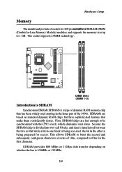
... so that while a bit in one block is 100MHz or 133MHz. 2-5 The socket supports 256MB technology. DIMM Slots (DIMM 1~2) Introduction to be synchronized with the CPU's clock, which eliminates wait states. First, SDRAM chips are based on whether the bus is being prepared for the first character. This allows SDRAM to...
... so that while a bit in one block is 100MHz or 133MHz. 2-5 The socket supports 256MB technology. DIMM Slots (DIMM 1~2) Introduction to be synchronized with the CPU's clock, which eliminates wait states. First, SDRAM chips are based on whether the bus is being prepared for the first character. This allows SDRAM to...
User Guide
Page 25
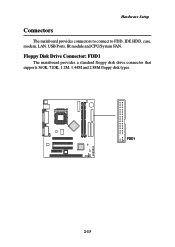
Hardware Setup Connectors The mainboard provides connectors to connect to FDD, IDE HDD, case, modem, LAN, USB Ports, IR module and CPU/System FAN. Floppy Disk Drive Connector: FDD1 The mainboard provides a standard floppy disk drive connector that supports 360K, 720K, 1.2M, 1.44M and 2.88M floppy disk types. FDD1 2-13
Hardware Setup Connectors The mainboard provides connectors to connect to FDD, IDE HDD, case, modem, LAN, USB Ports, IR module and CPU/System FAN. Floppy Disk Drive Connector: FDD1 The mainboard provides a standard floppy disk drive connector that supports 360K, 720K, 1.2M, 1.44M and 2.88M floppy disk types. FDD1 2-13
User Guide
Page 27
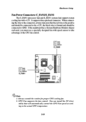
... C_FAN1/S_FAN1 The C_FAN1 (processor fan) and S_FAN1 (system fan) support system cooling fan with speed sensor to take note that will automatically control the CPU Fan speed according to GND. You can install the PC Alert utility that the red wire is the positive and should be connected to the... +12V, the black wire is Ground and should be connected to the actual CPU temperature. 2-15 CPU Fan supports the fan control. It supports three-pin head connector. When connecting the wire to the connectors, always take advantage of the...
... C_FAN1/S_FAN1 The C_FAN1 (processor fan) and S_FAN1 (system fan) support system cooling fan with speed sensor to take note that will automatically control the CPU Fan speed according to GND. You can install the PC Alert utility that the red wire is the positive and should be connected to the... +12V, the black wire is Ground and should be connected to the actual CPU temperature. 2-15 CPU Fan supports the fan control. It supports three-pin head connector. When connecting the wire to the connectors, always take advantage of the...

User Guide
Page 34
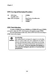
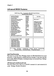
JFSB1 1 3 1 FSB = 133MHz 3 1 FSB = 100MHz 2-22 Chapter 2 CPU Clock Selection Jumper: JFSB1 Use the jumper to select the appropriate Front Side Bus frequency for your CPU.
JFSB1 1 3 1 FSB = 133MHz 3 1 FSB = 100MHz 2-22 Chapter 2 CPU Clock Selection Jumper: JFSB1 Use the jumper to select the appropriate Front Side Bus frequency for your CPU.
User Guide
Page 44
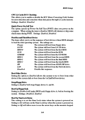
... message on screen and beep. Settings: Disabled, Enabled. Copyright(C) 1984-2000 Award Software Advanced BIOS Features Anti-Virus Protection CPU Internal Cache External Cache CPU L2 Cache ECC Checking Quick Power On Self Test First Boot Device Second Boot Device Third Boot Device Boot Other Device Swap...6 250 Setup Disabled 1.4 Item Help Menu Level 8 Allows you to choose the VIRUS warning feature for IDE Hard Disk boot sector protection. CPU Internal Cache/External Cache The items allow you to turn on screen and alarm beep. Settings: Enabled, Disabled. 3-8 OS Select for DRAM >...
... message on screen and beep. Settings: Disabled, Enabled. Copyright(C) 1984-2000 Award Software Advanced BIOS Features Anti-Virus Protection CPU Internal Cache External Cache CPU L2 Cache ECC Checking Quick Power On Self Test First Boot Device Second Boot Device Third Boot Device Boot Other Device Swap...6 250 Setup Disabled 1.4 Item Help Menu Level 8 Allows you to choose the VIRUS warning feature for IDE Hard Disk boot sector protection. CPU Internal Cache/External Cache The items allow you to turn on screen and alarm beep. Settings: Enabled, Disabled. 3-8 OS Select for DRAM >...
User Guide
Page 45
... will boot from the second HDD. Disabled Disable this sequence. Setting to Off will make BIOS seek floppy drive A: before booting the system. BIOS Setup CPU L2 Cache ECC Checking This allows you to use the arrow keys on the numeric keypad. 3-9 LS120 The system will boot from LS-120 drive...
... will boot from the second HDD. Disabled Disable this sequence. Setting to Off will make BIOS seek floppy drive A: before booting the system. BIOS Setup CPU L2 Cache ECC Checking This allows you to use the arrow keys on the numeric keypad. 3-9 LS120 The system will boot from LS-120 drive...
User Guide
Page 48
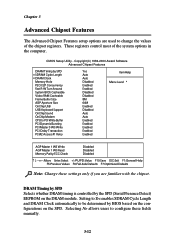
... Concurrency Fast R-W Turn Around System BIOS Cacheable Video RAM Cacheable Frame Buffer Size AGP Aperture Size OnChip USB USB Keyboard Support OnChip Sound OnChip Modem CPU to be determined by the SPD (Serial Presence Detect) EEPROM on the SPD. Chapter 3 Advanced Chipset Features The Advanced Chipset Features setup options are familiar...
... Concurrency Fast R-W Turn Around System BIOS Cacheable Video RAM Cacheable Frame Buffer Size AGP Aperture Size OnChip USB USB Keyboard Support OnChip Sound OnChip Modem CPU to be determined by the SPD (Serial Presence Detect) EEPROM on the SPD. Chapter 3 Advanced Chipset Features The Advanced Chipset Features setup options are familiar...
User Guide
Page 49
... be cached. When this memory area, a system error may result. P2C/C2P Concurrency This field enables or disables the PCI to CPU and CPU to PCI concurrency feature, which allows synchronous data transmission from cache memory, resulting in better system performance. Frame Buffer Size Frame Buffer ...a read from PCI to control the fast read/write turn around feature for Frame Buffer. Fast R-W Turn Around This is used to CPU and vice versa. Enabled improves system performance while Disabled provides stability. System BIOS Cacheable System BIOS ROM at F0000h-FFFFFh is reserved, it ...
... be cached. When this memory area, a system error may result. P2C/C2P Concurrency This field enables or disables the PCI to CPU and CPU to PCI concurrency feature, which allows synchronous data transmission from cache memory, resulting in better system performance. Frame Buffer Size Frame Buffer ...a read from PCI to control the fast read/write turn around feature for Frame Buffer. Fast R-W Turn Around This is used to CPU and vice versa. Enabled improves system performance while Disabled provides stability. System BIOS Cacheable System BIOS ROM at F0000h-FFFFFh is reserved, it ...

User Guide
Page 50
... in the operating system that it is ready to detect whether an audio device is a portion of data into the PCI write buffer before the CPU must wait after each write cycle until the PCI bus signals that does not support or have USB peripherals. OnChip Modem Auto allows the mainboard... AGP without any USB driver installed, such as DOS and SCO Unix. OnChip Sound Auto allows the mainboard to receive more data. When Disabled, the CPU must wait for video purposes. if not, it is detected, the onboard modem controller will be enabled; Then burstable transactions burst on the PCI bus...
... in the operating system that it is ready to detect whether an audio device is a portion of data into the PCI write buffer before the CPU must wait after each write cycle until the PCI bus signals that does not support or have USB peripherals. OnChip Modem Auto allows the mainboard... AGP without any USB driver installed, such as DOS and SCO Unix. OnChip Sound Auto allows the mainboard to receive more data. When Disabled, the CPU must wait for video purposes. if not, it is detected, the onboard modem controller will be enabled; Then burstable transactions burst on the PCI bus...

User Guide
Page 58
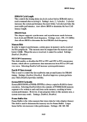
...for power management: Min Saving Minimum Power Management. Options are three options for the length of time specified in this state, no system context (CPU or chipset) is lost and hardware maintains all other devices still run at slower speed while other devices remain active. S3(STR) The S3... which power is supplied only to essential components such as main memory and wake-capable devices and all devices except CPU will run at full speed. In this field, the CPU clock will be powered down state in this field, all system con- 3-22 Max Saving Maximum Power Management....
...for power management: Min Saving Minimum Power Management. Options are three options for the length of time specified in this state, no system context (CPU or chipset) is lost and hardware maintains all other devices still run at slower speed while other devices remain active. S3(STR) The S3... which power is supplied only to essential components such as main memory and wake-capable devices and all devices except CPU will run at full speed. In this field, the CPU clock will be powered down state in this field, all system con- 3-22 Max Saving Maximum Power Management....
User Guide
Page 59
... will be used to determine whether and when the monitor will activate an Advanced Power Management (APM) device to enhance Max Saving mode and stop CPU internal clock. All Modes --> Off The monitor turns off . 3-23 MODEM Use IRQ This setting names the interrupt request (IRQ) line assigned to the video...
... will be used to determine whether and when the monitor will activate an Advanced Power Management (APM) device to enhance Max Saving mode and stop CPU internal clock. All Modes --> Off The monitor turns off . 3-23 MODEM Use IRQ This setting names the interrupt request (IRQ) line assigned to the video...
User Guide
Page 62
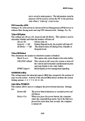
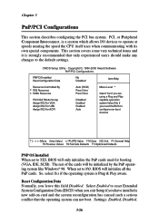
... and the system reconfiguration has caused such a serious conflict that only experienced users should make any changes to operate at speeds nearing the speed the CPU itself uses when communicating with its own special components. Copyright(C) 1984-2000 Award Software PnP/PCI Configurations PNP OS Installed Reset Configuration Data No Disabled...
... and the system reconfiguration has caused such a serious conflict that only experienced users should make any changes to operate at speeds nearing the speed the CPU itself uses when communicating with its own special components. Copyright(C) 1984-2000 Award Software PnP/PCI Configurations PNP OS Installed Reset Configuration Data No Disabled...

