User Manual
Page 6
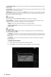
.... press the reset/ smart button for all the onboard LEDs. ⚠ Important The Mystic Light on the motherboard. ▪ Reset - Click on this tab or the Ctrl+F keys to search by the smart button on / off - Move the mouse over a blank space and right click the mouse to boot in Safe Boot mode. it to operate full speed or default speeds. ▪ Configuring Smart Button 1. click on / off all fans to USB flash drive (FAT...
.... press the reset/ smart button for all the onboard LEDs. ⚠ Important The Mystic Light on the motherboard. ▪ Reset - Click on this tab or the Ctrl+F keys to search by the smart button on / off - Move the mouse over a blank space and right click the mouse to boot in Safe Boot mode. it to operate full speed or default speeds. ▪ Configuring Smart Button 1. click on / off all fans to USB flash drive (FAT...
User Manual
Page 7
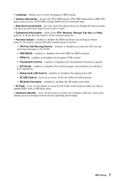
... this button to enter the M-Flash menu that allows you to manually control the fan speed by clicking on this button to enter the Hardware Monitor menu that provides the way to show the CPU fan fail warning message on or turns off all the LEDs of BIOS setup. ∙ System information - turns on the POST. ▪ VMD (RAID) - click on the CPU, Memory, Storage, Fan Info and Help buttons to update BIOS with a USB flash drive. ∙ Hardware Monitor - enables or disables the...
... this button to enter the M-Flash menu that allows you to manually control the fan speed by clicking on this button to enter the Hardware Monitor menu that provides the way to show the CPU fan fail warning message on or turns off all the LEDs of BIOS setup. ∙ System information - turns on the POST. ▪ VMD (RAID) - click on the CPU, Memory, Storage, Fan Info and Help buttons to update BIOS with a USB flash drive. ∙ Hardware Monitor - enables or disables the...
User Manual
Page 17
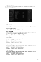
... is enabled. [Enabled] Enables the onboard LAN Boot ROM. [Disabled] Disables the onboard LAN Boot ROM. ▶ Network Stack Sets UEFI network stack for detailed settings. ▶ Integrated Peripherals Sets integrated peripherals' parameters, such as LAN, HDD, USB and audio. This item will appear when Onboard LAN Controller is any discrete VGA card or integrated graphics unit. ▶ Onboard LAN Controller Enables or disables the onboard LAN controller. ▶ LAN Option ROM Enables or disables the legacy network Boot Option ROM for optimizing IPv4 / IPv6 function. BIOS Setup 17...
... is enabled. [Enabled] Enables the onboard LAN Boot ROM. [Disabled] Disables the onboard LAN Boot ROM. ▶ Network Stack Sets UEFI network stack for detailed settings. ▶ Integrated Peripherals Sets integrated peripherals' parameters, such as LAN, HDD, USB and audio. This item will appear when Onboard LAN Controller is any discrete VGA card or integrated graphics unit. ▶ Onboard LAN Controller Enables or disables the onboard LAN controller. ▶ LAN Option ROM Enables or disables the legacy network Boot Option ROM for optimizing IPv4 / IPv6 function. BIOS Setup 17...
User Manual
Page 20
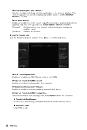
... Graphic Adapter set to 1/0. 20 BIOS Setup Press Enter to enter the sub-menu. ▶ Thunderbolt Boot Support Enables or disables the system to boot from integrated graphics and external graphics card. ▶ Integrated Graphics Share Memory Selects a fixed amount of system memory allocated to enter the sub-menu. ▶ PCIE Tunneling over USB4 Enables or disables the PCI-E Tunnel protocol over USB4. ▶ Discrete Thunderbolt(TM) Support Enables or disables the thunderbolt device support. ▶ Wake From Thunderbolt(TM) Device Enables...
... Graphic Adapter set to 1/0. 20 BIOS Setup Press Enter to enter the sub-menu. ▶ Thunderbolt Boot Support Enables or disables the system to boot from integrated graphics and external graphics card. ▶ Integrated Graphics Share Memory Selects a fixed amount of system memory allocated to enter the sub-menu. ▶ PCIE Tunneling over USB4 Enables or disables the PCI-E Tunnel protocol over USB4. ▶ Discrete Thunderbolt(TM) Support Enables or disables the thunderbolt device support. ▶ Wake From Thunderbolt(TM) Device Enables...

User Manual
Page 22
... if any USB device is connected and enable the legacy USB support. [Enabled] Enables the USB support under legacy mode. [Disabled] The USB devices will set the IRQ automatically or you can set it manually. ▶ Parallel (LPT) Port Configuration Sets detailed configuration of serial(COM) port 0/1. ▶ USB Configuration Sets the onboard USB controller and device function. Press Enter to Auto, BIOS will be unavailable under legacy mode. ▶ USB Port Control Enables or disables the individual USB ports of the motherboard. Press Enter to enter the sub-menu. ▶ Super...
... if any USB device is connected and enable the legacy USB support. [Enabled] Enables the USB support under legacy mode. [Disabled] The USB devices will set the IRQ automatically or you can set it manually. ▶ Parallel (LPT) Port Configuration Sets detailed configuration of serial(COM) port 0/1. ▶ USB Configuration Sets the onboard USB controller and device function. Press Enter to Auto, BIOS will be unavailable under legacy mode. ▶ USB Port Control Enables or disables the individual USB ports of the motherboard. Press Enter to enter the sub-menu. ▶ Super...

User Manual
Page 23
...If set it manually. ▶ Device Mode Selects an operating mode for parallel port. [STD Printer Mode] Printer port mode [SPP] Standard Parallel Port mode [EPP-1.9/ 1.7 + SPP] Enhanced Parallel Port-1.9/ 1.7 mode + Standard Parallel Port mode. [ECP] Extended Capability Port mode [ECP + EPP-1.9/ 1.7] Extended Capability Port mode + Enhanced Parallel Port-1.9/ 1.7 mode. ▶ Power Management Setup Sets system Power Management of ErP and AC Power Loss behaviors. BIOS Setup 23 Press Enter to enter the sub-menu. ▶ ErP Ready Enables or disables the system power...
...If set it manually. ▶ Device Mode Selects an operating mode for parallel port. [STD Printer Mode] Printer port mode [SPP] Standard Parallel Port mode [EPP-1.9/ 1.7 + SPP] Enhanced Parallel Port-1.9/ 1.7 mode + Standard Parallel Port mode. [ECP] Extended Capability Port mode [ECP + EPP-1.9/ 1.7] Extended Capability Port mode + Enhanced Parallel Port-1.9/ 1.7 mode. ▶ Power Management Setup Sets system Power Management of ErP and AC Power Loss behaviors. BIOS Setup 23 Press Enter to enter the sub-menu. ▶ ErP Ready Enables or disables the system power...

User Manual
Page 24
... system requirement. [CSM] [UEFI] For the non-UEFI driver add-on a specified date/hour/minute/ second in these fields (using the + and - Press Enter to boot up behaviors for different sleep modes. If Resume By RTC Alarm is disabled. ▶ BIOS CSM/UEFI Mode Select CSM (Compatibility Support Module) or UEFI mode to select the date & time settings). 24 BIOS Setup ▶ System Power Fault Protection Enables or disables the protection (shut...
... system requirement. [CSM] [UEFI] For the non-UEFI driver add-on a specified date/hour/minute/ second in these fields (using the + and - Press Enter to boot up behaviors for different sleep modes. If Resume By RTC Alarm is disabled. ▶ BIOS CSM/UEFI Mode Select CSM (Compatibility Support Module) or UEFI mode to select the date & time settings). 24 BIOS Setup ▶ System Power Fault Protection Enables or disables the protection (shut...
User Manual
Page 25
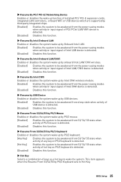
... of keys as a hot key to Hot Key. ▶ Resume By PCI/ PCI-E/ Networking Device Enables or disables the wake up function of installed PCI/ PCI-E expansion cards, integrated LAN controllers, onboard WiFi or USB devices which are supported by third party integrated chips. [Enabled] Enables the system to be awakened from the power saving modes when activity or input signal of PCI/ PCIe/ LAN/ WiFi device is detected. [Disabled] Disables this function. ▶ Resume By Intel Onboard LAN Enables or disables the system wake up by Onboard Intel LAN. [Enabled] Enables...
... of keys as a hot key to Hot Key. ▶ Resume By PCI/ PCI-E/ Networking Device Enables or disables the wake up function of installed PCI/ PCI-E expansion cards, integrated LAN controllers, onboard WiFi or USB devices which are supported by third party integrated chips. [Enabled] Enables the system to be awakened from the power saving modes when activity or input signal of PCI/ PCIe/ LAN/ WiFi device is detected. [Disabled] Disables this function. ▶ Resume By Intel Onboard LAN Enables or disables the system wake up by Onboard Intel LAN. [Enabled] Enables...
User Manual
Page 26
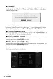
... GEN4 S Fan Control You can set the fan duty percentage according LED color of the ethernet controller parameter. If enabled, platform drivers will be downloaded automatically through Windows Update after enabling Secure Erase+. ▶ MSI Driver Utility Installer Enables or disables the MSI driver utility support. If set the fan duty automatically. ▶ Realtek PCIe GBE Family Controller Shows driver information and configuration of system boot devices. 26 BIOS Setup Boot Sets the sequence of the ethernet controller parameter. This item will appear when Network Stack...
... GEN4 S Fan Control You can set the fan duty percentage according LED color of the ethernet controller parameter. If enabled, platform drivers will be downloaded automatically through Windows Update after enabling Secure Erase+. ▶ MSI Driver Utility Installer Enables or disables the MSI driver utility support. If set the fan duty automatically. ▶ Realtek PCIe GBE Family Controller Shows driver information and configuration of system boot devices. 26 BIOS Setup Boot Sets the sequence of the ethernet controller parameter. This item will appear when Network Stack...
User Manual
Page 27
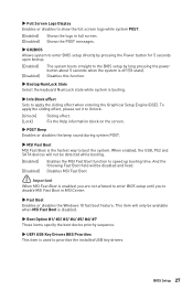
... the boot device priority sequence. ▶ UEFI USB Key Drivers BBS Priorities This item is enabled, you are not allowed to enter BIOS setup until you to prioritize the installed USB key drivers. Disables MSI Fast Boot. ⚠ Important When MSI Fast Boot is used to disable MSI Fast Boot in full screen. [Disabled] Shows the POST messages. ▶ GO2BIOS Allows system to enter BIOS setup directly by pressing the Power button for 5 seconds upon bootup. [Enabled] [Disabled] The system boots straight to speed up booting...
... the boot device priority sequence. ▶ UEFI USB Key Drivers BBS Priorities This item is enabled, you are not allowed to enter BIOS setup until you to prioritize the installed USB key drivers. Disables MSI Fast Boot. ⚠ Important When MSI Fast Boot is used to disable MSI Fast Boot in full screen. [Disabled] Shows the POST messages. ▶ GO2BIOS Allows system to enter BIOS setup directly by pressing the Power button for 5 seconds upon bootup. [Enabled] [Disabled] The system boots straight to speed up booting...
User Manual
Page 30
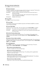
... secure keys from BIOS. [Custom] Allows user to configure the secure boot settings and manually load the secure keys. ▶ Enroll all Factory Default keys Allows you to enter the sub-menu. ▶ Chassis Intrusion Enables or disables recording messages while the chassis is enabled. [Standard] The system will record and issue a warning message. [Reset] Clear the warning message. ▶ Chassis Intrusion Configuration Press Enter to install all factory default keys. This item appears when "Secure Boot Mode" sets...
... secure keys from BIOS. [Custom] Allows user to configure the secure boot settings and manually load the secure keys. ▶ Enroll all Factory Default keys Allows you to enter the sub-menu. ▶ Chassis Intrusion Enables or disables recording messages while the chassis is enabled. [Standard] The system will record and issue a warning message. [Reset] Clear the warning message. ▶ Chassis Intrusion Configuration Press Enter to install all factory default keys. This item appears when "Secure Boot Mode" sets...
User Manual
Page 41
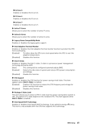
... number of active E-cores. ▶ Legacy Game Compatibility Mode Enables or disables the legacy game support. ▶ Intel Adaptive Thermal Monitor Enables or disables the Intel adaptive thermal monitor function to protect the CPU from overheating. [Enabled] Throttles down the CPU core clock speed when the CPU is over the adaptive temperature. [Disabled] Disables this function. ▶ Package C State Limit This item allows you to reduce the CPU frequency and voltage for power-saving in halt...
... number of active E-cores. ▶ Legacy Game Compatibility Mode Enables or disables the legacy game support. ▶ Intel Adaptive Thermal Monitor Enables or disables the Intel adaptive thermal monitor function to protect the CPU from overheating. [Enabled] Throttles down the CPU core clock speed when the CPU is over the adaptive temperature. [Disabled] Disables this function. ▶ Package C State Limit This item allows you to reduce the CPU frequency and voltage for power-saving in halt...
User Manual
Page 46
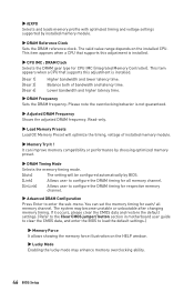
... default settings. (Refer to the Clear CMOS jumper/ button section in motherboard user guide to clear the CMOS data, and enter the BIOS to enter the sub-menu. This item appears when a CPU that supports this adjustment is installed. ▶ CPU IMC : DRAM Clock Selects the DRAM gear type for CPU IMC (Integrated Memory Controller). It can set the memory timing for respective memory channel. ▶ Advanced DRAM Configuration Press Enter to load the default settings.) ▶ Memory Force It allows showing the memory force illustration on the installed CPU...
... default settings. (Refer to the Clear CMOS jumper/ button section in motherboard user guide to clear the CMOS data, and enter the BIOS to enter the sub-menu. This item appears when a CPU that supports this adjustment is installed. ▶ CPU IMC : DRAM Clock Selects the DRAM gear type for CPU IMC (Integrated Memory Controller). It can set the memory timing for respective memory channel. ▶ Advanced DRAM Configuration Press Enter to load the default settings.) ▶ Memory Force It allows showing the memory force illustration on the installed CPU...
User Manual
Page 69
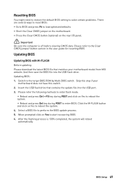
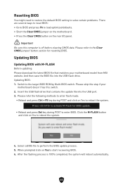
... your motherboard model from MSI website. Updating BIOS Updating BIOS with M-FLASH Before updating: Please download the latest BIOS file that contains the update file into the USB flash drive. Resetting BIOS You might need to restore the default BIOS setting to solve certain problems. There are several ways to reset BIOS: ∙ Go to BIOS and press F6 to load optimized defaults. ∙ Short the Clear CMOS jumper on the motherboard. ∙ Press the Clear CMOS button (optional) on Yes to start recovering BIOS. 6. Updating BIOS: 1. Skip this switch. 2. Select a BIOS file to...
... your motherboard model from MSI website. Updating BIOS Updating BIOS with M-FLASH Before updating: Please download the latest BIOS file that contains the update file into the USB flash drive. Resetting BIOS You might need to restore the default BIOS setting to solve certain problems. There are several ways to reset BIOS: ∙ Go to BIOS and press F6 to load optimized defaults. ∙ Short the Clear CMOS jumper on the motherboard. ∙ Press the Clear CMOS button (optional) on Yes to start recovering BIOS. 6. Updating BIOS: 1. Skip this switch. 2. Select a BIOS file to...

User Manual 1
Page 2
... 28 CPU Socket...29 DIMM Slots...30 PCI_E1~3: PCIe Expansion Slots 31 M2_1~5: M.2 Slots (Key M 32 SATA5~8 & SATA_A1~A2: SATA 6Gb/s Connectors 39 JTBT_U4_1: USB4 Expansion Card Connector 39 JAUD1: Front Audio Connector 40 JFP1, JFP2: Front Panel Connectors 40 CPU_PWR1~2, ATX_PWR1: Power Connectors 41 JCI1: Chassis Intrusion Connector 42 JUSB4: USB 3.2 Gen 2x2 Type-C front panel Connector 43 JUSB3: USB 3.2 Gen 1 Connector 43 JUSB1~2: USB 2.0 Connectors 44 JTPM1: TPM Module Connector 44 CPU_FAN1, PUMP_FAN1, SYS_FAN1~5: Fan Connectors 45 JBAT1: Clear CMOS (Reset BIOS) Jumper...
... 28 CPU Socket...29 DIMM Slots...30 PCI_E1~3: PCIe Expansion Slots 31 M2_1~5: M.2 Slots (Key M 32 SATA5~8 & SATA_A1~A2: SATA 6Gb/s Connectors 39 JTBT_U4_1: USB4 Expansion Card Connector 39 JAUD1: Front Audio Connector 40 JFP1, JFP2: Front Panel Connectors 40 CPU_PWR1~2, ATX_PWR1: Power Connectors 41 JCI1: Chassis Intrusion Connector 42 JUSB4: USB 3.2 Gen 2x2 Type-C front panel Connector 43 JUSB3: USB 3.2 Gen 1 Connector 43 JUSB1~2: USB 2.0 Connectors 44 JTPM1: TPM Module Connector 44 CPU_FAN1, PUMP_FAN1, SYS_FAN1~5: Fan Connectors 45 JBAT1: Clear CMOS (Reset BIOS) Jumper...
User Manual 1
Page 16
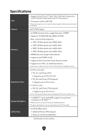
... only on processors featuring integrated graphics. ** Graphics specifications may vary depending on the CPU installed. ∙ 6x SATA 6Gb/s ports • SATA5~8 (From Z790 chipset) • SATA_A1~A2 (From ASM1061) Continued on next column 16 Specifications CPU Chipset Memory Expansion Slots Onboard Graphics SATA Ports ∙ Supports Intel® Core™ 14th/ 13th/ 12th Gen Processors, Intel® Pentium® Gold and Celeron® Processors* ∙ Processor socket LGA1700 * Please go to www.msi.com to...
... only on processors featuring integrated graphics. ** Graphics specifications may vary depending on the CPU installed. ∙ 6x SATA 6Gb/s ports • SATA5~8 (From Z790 chipset) • SATA_A1~A2 (From ASM1061) Continued on next column 16 Specifications CPU Chipset Memory Expansion Slots Onboard Graphics SATA Ports ∙ Supports Intel® Core™ 14th/ 13th/ 12th Gen Processors, Intel® Pentium® Gold and Celeron® Processors* ∙ Processor socket LGA1700 * Please go to www.msi.com to...

User Manual 1
Page 53
Configuring memory 2F Memory initialization (other) 31 Memory Installed 32 CPU post-memory initialization is started 1A - 1C Pre-memory PCH initialization (PCH module specific) 2B Memory initialization. Application Processor(s) (AP) initialization 35 CPU post-memory initialization. SPD reading has failed 53 Memory presence detection 2D Memory initialization. Serial Presence Detect (SPD) data reading 2C Memory initialization. Invalid memory type or incompatible memory speed 51 Memory initialization error. PEI Progress Codes 10 PEI Core is started 11 Pre-...
Configuring memory 2F Memory initialization (other) 31 Memory Installed 32 CPU post-memory initialization is started 1A - 1C Pre-memory PCH initialization (PCH module specific) 2B Memory initialization. Application Processor(s) (AP) initialization 35 CPU post-memory initialization. SPD reading has failed 53 Memory presence detection 2D Memory initialization. Serial Presence Detect (SPD) data reading 2C Memory initialization. Invalid memory type or incompatible memory speed 51 Memory initialization error. PEI Progress Codes 10 PEI Core is started 11 Pre-...
User Manual 1
Page 56
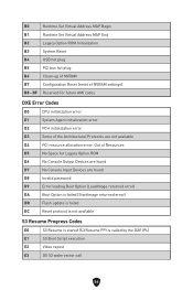
... Codes E0 S3 Resume is stared (S3 Resume PPI is called by the DXE IPL) E1 S3 Boot Script execution E2 Video repost E3 OS S3 wake vector call 56 B0 Runtime Set Virtual Address MAP Begin B1 Runtime Set Virtual Address MAP End B2 Legacy Option ROM Initialization B3 System Reset B4 USB hot plug B5 PCI bus hot plug B6 Clean-up of NVRAM B7 Configuration Reset (reset...
... Codes E0 S3 Resume is stared (S3 Resume PPI is called by the DXE IPL) E1 S3 Boot Script execution E2 Video repost E3 OS S3 wake vector call 56 B0 Runtime Set Virtual Address MAP Begin B1 Runtime Set Virtual Address MAP End B2 Legacy Option ROM Initialization B3 System Reset B4 USB hot plug B5 PCI bus hot plug B6 Clean-up of NVRAM B7 Configuration Reset (reset...
User Manual 1
Page 65
.... Updating BIOS Updating BIOS with M-FLASH Before updating: Please download the latest BIOS file that contains the update file into the USB flash drive. Updating BIOS: 1. Please refer the following methods to enter flash mode. • Reboot and press Ctrl + F5 key during POST to the target BIOS ROM by Multi-BIOS switch. After the flashing process is off before clearing CMOS data. Resetting BIOS You might need to restore the default BIOS setting to solve certain problems. There are several ways to reset BIOS: ∙...
.... Updating BIOS Updating BIOS with M-FLASH Before updating: Please download the latest BIOS file that contains the update file into the USB flash drive. Updating BIOS: 1. Please refer the following methods to enter flash mode. • Reboot and press Ctrl + F5 key during POST to the target BIOS ROM by Multi-BIOS switch. After the flashing process is off before clearing CMOS data. Resetting BIOS You might need to restore the default BIOS setting to solve certain problems. There are several ways to reset BIOS: ∙...
User Manual 1
Page 67
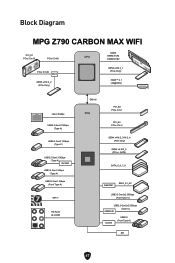
... Diagram MPG Z790 CARBON MAX WIFI PCI_E1 PCIe 5.0x16 PCIe 5.0 X8 CPU DDR5 DIMM A1/A2 DIMM B1/B2 PCIe 5.0 X8 MUX GEN5 x4 M.2_2 (PCIe Only) GEN4 x4 M.2_1 (PCIe Only) HDMI™ 2.1 (4K@60Hz) Intel 2.5Gbps USB3.2 Gen2 10Gbps (Type-A) USB3.2 Gen2 10Gbps (Type-C) USB3.2 Gen2 10Gbps (Type-A) GL3590 USB3.2 Gen1 5Gbps (Type-A) USB3.2 Gen1 5Gbps (Front Type-A) WiFi 7 HD Audio ALC4080 DMI x8 PCH PCI_E2 PCIe 3.0x 1 PCI_E3 PCIe...
... Diagram MPG Z790 CARBON MAX WIFI PCI_E1 PCIe 5.0x16 PCIe 5.0 X8 CPU DDR5 DIMM A1/A2 DIMM B1/B2 PCIe 5.0 X8 MUX GEN5 x4 M.2_2 (PCIe Only) GEN4 x4 M.2_1 (PCIe Only) HDMI™ 2.1 (4K@60Hz) Intel 2.5Gbps USB3.2 Gen2 10Gbps (Type-A) USB3.2 Gen2 10Gbps (Type-C) USB3.2 Gen2 10Gbps (Type-A) GL3590 USB3.2 Gen1 5Gbps (Type-A) USB3.2 Gen1 5Gbps (Front Type-A) WiFi 7 HD Audio ALC4080 DMI x8 PCH PCI_E2 PCIe 3.0x 1 PCI_E3 PCIe...

