User Manual
Page 1
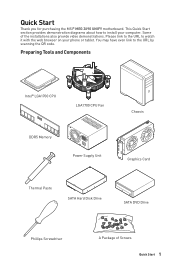
... MSI® MEG Z690 UNIFY motherboard. Please link to the URL to watch it with the web browser on your computer. Preparing Tools and Components Intel® LGA1700 CPU LGA1700 CPU Fan DDR5 Memory Power Supply Unit Chassis Graphics Card Thermal Paste SATA Hard Disk Drive SATA DVD Drive Phillips Screwdriver A Package of the installations also provide video demonstrations. This Quick Start section provides demonstration diagrams about how to the URL by scanning the QR code...
... MSI® MEG Z690 UNIFY motherboard. Please link to the URL to watch it with the web browser on your computer. Preparing Tools and Components Intel® LGA1700 CPU LGA1700 CPU Fan DDR5 Memory Power Supply Unit Chassis Graphics Card Thermal Paste SATA Hard Disk Drive SATA DVD Drive Phillips Screwdriver A Package of the installations also provide video demonstrations. This Quick Start section provides demonstration diagrams about how to the URL by scanning the QR code...

User Manual
Page 13
... a Processor 4 Installing DDR5 memory 5 Connecting the Front Panel Header 6 Installing the Motherboard 7 Connecting the Power Connectors 8 Installing SATA Drives 9 Installing a Graphics Card 10 Connecting Peripheral Devices 11 Power On...12 Specifications...15 Package contents 22 Block Diagram ...23 Rear I/O Panel...24 LAN Port LED Status Table 24 Audio Ports Configuration 24 Realtek Audio Console 25 Installing Antennas 27 Overview of Components 28 CPU Socket...30 DIMM Slots...31 PCI_E1~3: PCIe Expansion Slots 32 JFP1, JFP2: Front Panel Connectors 33 M2_1~5: M.2 Slots (Key...
... a Processor 4 Installing DDR5 memory 5 Connecting the Front Panel Header 6 Installing the Motherboard 7 Connecting the Power Connectors 8 Installing SATA Drives 9 Installing a Graphics Card 10 Connecting Peripheral Devices 11 Power On...12 Specifications...15 Package contents 22 Block Diagram ...23 Rear I/O Panel...24 LAN Port LED Status Table 24 Audio Ports Configuration 24 Realtek Audio Console 25 Installing Antennas 27 Overview of Components 28 CPU Socket...30 DIMM Slots...31 PCI_E1~3: PCIe Expansion Slots 32 JFP1, JFP2: Front Panel Connectors 33 M2_1~5: M.2 Slots (Key...
User Manual
Page 14
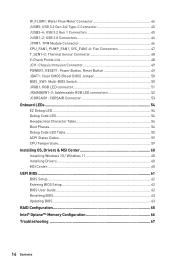
...BIOS Switch 50 JRGB1: RGB LED connector 51 JRAINBOW1~2: Addressable RGB LED connectors 52 JCORSAIR1: CORSAIR Connector 53 Onboard LEDs...54 EZ Debug LED...54 Debug Code LED...54 Hexadecimal Character Table 54 Boot Phases...54 Debug Code LED Table 55 ACPI States Codes 59 CPU Temperature 59 Installing OS, Drivers & MSI Center 60 Installing Windows 10 / Windows 11 60 Installing Drivers 60 MSI Center...60 UEFI BIOS...61 BIOS Setup...62 Entering BIOS Setup 62 BIOS User Guide...62 Resetting BIOS...63 Updating BIOS...63 RAID Configuration 65 Intel® Optane™ Memory Configuration...
...BIOS Switch 50 JRGB1: RGB LED connector 51 JRAINBOW1~2: Addressable RGB LED connectors 52 JCORSAIR1: CORSAIR Connector 53 Onboard LEDs...54 EZ Debug LED...54 Debug Code LED...54 Hexadecimal Character Table 54 Boot Phases...54 Debug Code LED Table 55 ACPI States Codes 59 CPU Temperature 59 Installing OS, Drivers & MSI Center 60 Installing Windows 10 / Windows 11 60 Installing Drivers 60 MSI Center...60 UEFI BIOS...61 BIOS Setup...62 Entering BIOS Setup 62 BIOS User Guide...62 Resetting BIOS...63 Updating BIOS...63 RAID Configuration 65 Intel® Optane™ Memory Configuration...
User Manual
Page 15
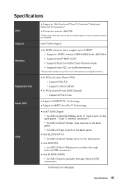
... compatible memory ∙∙2x PCIe x16 slots (From CPU) ▫▫Support PCIe 5.0 ▫▫Support x16/ x0, x8/ x8 ∙∙1x PCIe x4 slot (From Z690 Chipset) ▫▫Supports PCIe 3.0 x4 ∙∙Supports NVIDIA® SLI Technology ∙∙Supports AMD® CrossFire™ Technology ∙∙Intel® Z690 Chipset ▪▪2x USB 3.2 Gen2x2 20Gbps ports ( 1 Type-C port on the back panel, 1 Type-C internal connector) ▪▪3x USB 3.2 Gen2 10Gbps Type-A ports on the back panel...
... compatible memory ∙∙2x PCIe x16 slots (From CPU) ▫▫Support PCIe 5.0 ▫▫Support x16/ x0, x8/ x8 ∙∙1x PCIe x4 slot (From Z690 Chipset) ▫▫Supports PCIe 3.0 x4 ∙∙Supports NVIDIA® SLI Technology ∙∙Supports AMD® CrossFire™ Technology ∙∙Intel® Z690 Chipset ▪▪2x USB 3.2 Gen2x2 20Gbps ports ( 1 Type-C port on the back panel, 1 Type-C internal connector) ▪▪3x USB 3.2 Gen2 10Gbps Type-A ports on the back panel...

User Manual
Page 16
...;▫Supports 2260/ 2280 storage devices ▪▪M2_2~5 supports Intel® Optane™ Memory ∙∙Supports Intel® Smart Response Technology for Intel Core™ processors ∙∙Supports RAID 0, RAID 1, RAID 5 and RAID 10 for SATA storage devices* ∙∙Supports RAID 0, RAID 1, RAID 5 and RAID 10 for M.2 NVMe storage devices * SATAA & SATAB do not support RAID function. Realtek® ALC4080 Codec ∙∙7.1-Channel High Definition Audio ∙∙Supports S/PDIF output 2x Intel® I225-V 2.5Gbps LAN controllers...
...;▫Supports 2260/ 2280 storage devices ▪▪M2_2~5 supports Intel® Optane™ Memory ∙∙Supports Intel® Smart Response Technology for Intel Core™ processors ∙∙Supports RAID 0, RAID 1, RAID 5 and RAID 10 for SATA storage devices* ∙∙Supports RAID 0, RAID 1, RAID 5 and RAID 10 for M.2 NVMe storage devices * SATAA & SATAB do not support RAID function. Realtek® ALC4080 Codec ∙∙7.1-Channel High Definition Audio ∙∙Supports S/PDIF output 2x Intel® I225-V 2.5Gbps LAN controllers...

User Manual
Page 18
... Low temperature booting jumpers ∙∙1x Safe boot jumper ∙∙1x OC Retry jumper ∙∙1x 2-Digit Debug Code LED ∙∙4x EZ Debug LED ∙∙1x 4-pin RGB LED connector ∙∙2x 3-pin RAINBOW LED connectors ∙∙1x 3-pin JCORSAIR LED connector ∙∙1x Clear CMOS button ∙∙1x Flash BIOS button ∙∙1x PS/2 port ∙∙2x USB 2.0 Type-A ports ∙∙2x 2.5Gbps LAN (RJ45) ports ∙...
... Low temperature booting jumpers ∙∙1x Safe boot jumper ∙∙1x OC Retry jumper ∙∙1x 2-Digit Debug Code LED ∙∙4x EZ Debug LED ∙∙1x 4-pin RGB LED connector ∙∙2x 3-pin RAINBOW LED connectors ∙∙1x 3-pin JCORSAIR LED connector ∙∙1x Clear CMOS button ∙∙1x Flash BIOS button ∙∙1x PS/2 port ∙∙2x USB 2.0 Type-A ports ∙∙2x 2.5Gbps LAN (RJ45) ports ∙...

User Manual
Page 29
... Port Type Multi-BIOS Switch Fan Connectors Power Connectors LGA1700 CPU Socket Memory slots Front Audio Connector Clear CMOS (Reset BIOS) Jumper Chassis Intrusion Connector CORSAIR Connector Tuning Controller connector Front Panel Connectors Low Temperature Booting Jumper Safe Boot Jumper OC Retry Button Connector Addressable RGB LED connectors RGB LED connector Slow Mode Booting Jumper Thunderbolt Add-on Card Connector TPM Module Connector USB 2.0 Connectors USB 3.2 Gen 1 Connectors USB 3.2 Gen 2x2 Type-C Connector M.2 Slots (Key M) PCIe Expansion Slots Power Button, Reset Button SATA...
... Port Type Multi-BIOS Switch Fan Connectors Power Connectors LGA1700 CPU Socket Memory slots Front Audio Connector Clear CMOS (Reset BIOS) Jumper Chassis Intrusion Connector CORSAIR Connector Tuning Controller connector Front Panel Connectors Low Temperature Booting Jumper Safe Boot Jumper OC Retry Button Connector Addressable RGB LED connectors RGB LED connector Slow Mode Booting Jumper Thunderbolt Add-on Card Connector TPM Module Connector USB 2.0 Connectors USB 3.2 Gen 1 Connectors USB 3.2 Gen 2x2 Type-C Connector M.2 Slots (Key M) PCIe Expansion Slots Power Button, Reset Button SATA...

User Manual
Page 30
... installing or removing the CPU. ∙∙Please retain the CPU protective cap after installing the processor. Before attempting to overclock, please make sure the cooling fans work properly to protect the CPU from overheating. Any attempt to operate beyond product specifications. 30 Overview of the LGA1700 CPU has four notches and a golden triangle to assist in the heatsink/ cooler package for motherboard placement. MSI...
... installing or removing the CPU. ∙∙Please retain the CPU protective cap after installing the processor. Before attempting to overclock, please make sure the cooling fans work properly to protect the CPU from overheating. Any attempt to operate beyond product specifications. 30 Overview of the LGA1700 CPU has four notches and a golden triangle to assist in the heatsink/ cooler package for motherboard placement. MSI...
User Manual
Page 32
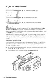
... cards, always turn off your graphics card to make sure you need to use a tool such as MSI Graphics Card Bolster to support its weight to prevent deformation of Components Installing SLI graphics cards For power supply recommendations for any necessary additional hardware or software changes. PCI_E1~3: PCIe Expansion Slots PCI_E1: PCIe 5.0 x16 (From CPU) PCI_E2: PCIe 5.0 x8 (From CPU) PCI_E3: PCIe 3.0 x4 (From Z690 Chipset) ⚠⚠Important ∙∙If you install a large and heavy graphics card...
... cards, always turn off your graphics card to make sure you need to use a tool such as MSI Graphics Card Bolster to support its weight to prevent deformation of Components Installing SLI graphics cards For power supply recommendations for any necessary additional hardware or software changes. PCI_E1~3: PCIe Expansion Slots PCI_E1: PCIe 5.0 x16 (From CPU) PCI_E2: PCIe 5.0 x8 (From CPU) PCI_E3: PCIe 3.0 x4 (From Z690 Chipset) ⚠⚠Important ∙∙If you install a large and heavy graphics card...

User Manual
Page 33
3. Connect all PCIe power connectors of Components 33 Reconnect the power cord, power up the computer and install the drivers and software included in the package, which is included in your graphics card package. 5. Right-click the Windows desktop and select NVIDIA Control Panel from the menu, click on the front panel. JFP2 1 + - + Buzzer Speaker 1 Speaker - 2 3 Buzzer - 4 Buzzer + Speaker + Power LED Power Switch - -+ -- ++ ⚠⚠Important A front panel extension cable is convenient for you 1 to connect the chassis to...
3. Connect all PCIe power connectors of Components 33 Reconnect the power cord, power up the computer and install the drivers and software included in the package, which is included in your graphics card package. 5. Right-click the Windows desktop and select NVIDIA Control Panel from the menu, click on the front panel. JFP2 1 + - + Buzzer Speaker 1 Speaker - 2 3 Buzzer - 4 Buzzer + Speaker + Power LED Power Switch - -+ -- ++ ⚠⚠Important A front panel extension cable is convenient for you 1 to connect the chassis to...

User Manual
Page 50
... or Flash BIOS Button to the other for details. 50 Overview of Components Use a jumper cap to clear the CMOS memory. Plug the power cord and Power on the motherboard to BIOS section for booting by sliding the switch. BIOS_SW1: Multi-BIOS Switch This motherboard has two built-in BIOS ROMs. If one is crashed, you want to clear the system configuration, set the jumpers to short JBAT1 for about 5-10 seconds. 3. Multi-BIOS LED (Red: BIOS B, White: BIOS A) BIOS B BIOS A (Default...
... or Flash BIOS Button to the other for details. 50 Overview of Components Use a jumper cap to clear the CMOS memory. Plug the power cord and Power on the motherboard to BIOS section for booting by sliding the switch. BIOS_SW1: Multi-BIOS Switch This motherboard has two built-in BIOS ROMs. If one is crashed, you want to clear the system configuration, set the jumpers to short JBAT1 for about 5-10 seconds. 3. Multi-BIOS LED (Red: BIOS B, White: BIOS A) BIOS B BIOS A (Default...

User Manual
Page 56
... incompatible memory speed 51 Memory initialization error. SPD reading has failed 52 Memory initialization error. Invalid memory size or memory modules do not match 53 Memory initialization error. 36 CPU post-memory initialization. No usable memory detected 54 Unspecified memory initialization error 55 Memory not installed 56 Invalid CPU type or Speed 57 CPU mismatch 58 CPU self test failed or possible CPU cache error 59 CPU micro-code is not found or micro-code update is failed 5A Internal CPU error 5B Reset...
... incompatible memory speed 51 Memory initialization error. SPD reading has failed 52 Memory initialization error. Invalid memory size or memory modules do not match 53 Memory initialization error. 36 CPU post-memory initialization. No usable memory detected 54 Unspecified memory initialization error 55 Memory not installed 56 Invalid CPU type or Speed 57 CPU mismatch 58 CPU self test failed or possible CPU cache error 59 CPU micro-code is not found or micro-code update is failed 5A Internal CPU error 5B Reset...
User Manual
Page 57
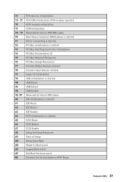
... is started PCI Bus Hot Plug Controller Initialization PCI Bus Enumeration 32 PCI Bus Request Resources PCI Bus Assign Resources Console Output devices connect Console input devices connect Super IO Initialization USB initialization is started USB Reset USB Detect USB Enable Reserved for future AMI codes IDE initialization is started IDE Reset IDE Detect IDE Enable SCSI initialization is started SCSI Reset SCSI Detect SCSI Enable Setup Verifying Password Start of Setup Setup Input Wait Ready To Boot event Legacy Boot event Exit Boot Services event Runtime Set Virtual Address MAP Begin Onboard...
... is started PCI Bus Hot Plug Controller Initialization PCI Bus Enumeration 32 PCI Bus Request Resources PCI Bus Assign Resources Console Output devices connect Console input devices connect Super IO Initialization USB initialization is started USB Reset USB Detect USB Enable Reserved for future AMI codes IDE initialization is started IDE Reset IDE Detect IDE Enable SCSI initialization is started SCSI Reset SCSI Detect SCSI Enable Setup Verifying Password Start of Setup Setup Input Wait Ready To Boot event Legacy Boot event Exit Boot Services event Runtime Set Virtual Address MAP Begin Onboard...
User Manual
Page 58
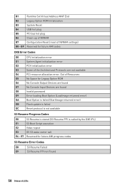
... Error Codes D0 CPU initialization error D1 System Agent initialization error D2 PCH initialization error D3 Some of NVRAM settings) B8 - B1 Runtime Set Virtual Address MAP End B2 Legacy Option ROM Initialization B3 System Reset B4 USB hot plug B5 PCI bus hot plug B6 Clean-up of NVRAM B7 Configuration Reset (reset of the Architectural Protocols are found D8 Invalid password D9 Error loading Boot Option (LoadImage returned error) DA Boot Option is failed (StartImage returned error) DB Flash update...
... Error Codes D0 CPU initialization error D1 System Agent initialization error D2 PCH initialization error D3 Some of NVRAM settings) B8 - B1 Runtime Set Virtual Address MAP End B2 Legacy Option ROM Initialization B3 System Reset B4 USB hot plug B5 PCI bus hot plug B6 Clean-up of NVRAM B7 Configuration Reset (reset of the Architectural Protocols are found D8 Invalid password D9 Error loading Boot Option (LoadImage returned error) DA Boot Option is failed (StartImage returned error) DB Flash update...
User Manual
Page 60
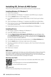
... Restart button on the screen to get into the USB port. 3. Press F11 key during the computer POST (Power-On Self Test) to install Windows 10 / Windows 11. message. Insert MSI® USB Drive into Boot Menu. 5. If you turn off the AutoPlay feature from the root path of the window. 6. With MSI Center, you easily optimize game settings and smoothly use content creation softwares. Installing Drivers 1. Click OK button to control and synchronize LED light effects...
... Restart button on the screen to get into the USB port. 3. Press F11 key during the computer POST (Power-On Self Test) to install Windows 10 / Windows 11. message. Insert MSI® USB Drive into Boot Menu. 5. If you turn off the AutoPlay feature from the root path of the window. 6. With MSI Center, you easily optimize game settings and smoothly use content creation softwares. Installing Drivers 1. Click OK button to control and synchronize LED light effects...
User Manual
Page 62
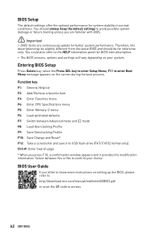
... mode F8: Load Overclocking Profile F9: Save Overclocking Profile F10: Save Change and Reset* F12: Take a screenshot and save it provides the modification information. You could also refer to USB flash drive (FAT/ FAT32 format only). Ctrl+F: Enter Search page * When you 'd like to know more instructions on setting up the BIOS, please refer to http://download.msi.com/manual/mb/Intel600BIOS.pdf or scan the QR code...
... mode F8: Load Overclocking Profile F9: Save Overclocking Profile F10: Save Change and Reset* F12: Take a screenshot and save it provides the modification information. You could also refer to USB flash drive (FAT/ FAT32 format only). Ctrl+F: Enter Search page * When you 'd like to know more instructions on setting up the BIOS, please refer to http://download.msi.com/manual/mb/Intel600BIOS.pdf or scan the QR code...
User Manual
Page 63
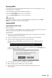
... if your motherboard model from MSI website. UEFI BIOS 63 Please refer to start recovering BIOS. 6. And then save the BIOS file into the USB port. 3. When prompted click on Yes to the Clear CMOS jumper/ button section for BIOS update. ▪▪Reboot and press Del key during POST and click on Yes to perform the BIOS update process. 5. Resetting BIOS You might need to restore the default BIOS setting to solve certain problems. There are...
... if your motherboard model from MSI website. UEFI BIOS 63 Please refer to start recovering BIOS. 6. And then save the BIOS file into the USB port. 3. When prompted click on Yes to the Clear CMOS jumper/ button section for BIOS update. ▪▪Reboot and press Del key during POST and click on Yes to perform the BIOS update process. 5. Resetting BIOS You might need to restore the default BIOS setting to solve certain problems. There are...
User Manual
Page 64
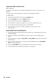
... Advance button. 3. Updating BIOS with MSI Center Before updating: ∙∙Make sure the LAN driver is already installed and the internet connection is set properly. ∙∙Please close all other application software before updating the BIOS. Please download the latest BIOS file that contains the MSI.ROM file into the Flash BIOS Port on it to MSI.ROM, and save it . 5. Plug the USB storage device that matches your motherboard model from the MSI® website. 2. To update BIOS: 1. After the flashing...
... Advance button. 3. Updating BIOS with MSI Center Before updating: ∙∙Make sure the LAN driver is already installed and the internet connection is set properly. ∙∙Please close all other application software before updating the BIOS. Please download the latest BIOS file that contains the MSI.ROM file into the Flash BIOS Port on it to MSI.ROM, and save it . 5. Plug the USB storage device that matches your motherboard model from the MSI® website. 2. To update BIOS: 1. After the flashing...

User Manual
Page 67
... known working LAN cable. Lost BIOS password ∙∙Clear the CMOS, but no signal to monitor ∙∙Connect the monitor power cord to a electrical outlet securely. ∙∙Make sure the monitor is turned on. ∙∙Select different inputs on the monitor. ∙∙If 3 long beeps are heard, remove all memory modules and try to go over troubleshooting guide first to see if your USB drive driver has been installed...
... known working LAN cable. Lost BIOS password ∙∙Clear the CMOS, but no signal to monitor ∙∙Connect the monitor power cord to a electrical outlet securely. ∙∙Make sure the monitor is turned on. ∙∙Select different inputs on the monitor. ∙∙If 3 long beeps are heard, remove all memory modules and try to go over troubleshooting guide first to see if your USB drive driver has been installed...
User Manual
Page 71
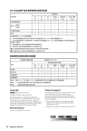
... changes to accuracy or completeness is a registered trademark of their respective owners. Copyright © 2021 All rights reserved. Alternatively, please try the following help resources for technical guide, BIOS updates, driver updates, and other marks and names mentioned may be obtained from the user guide, please contact your product at: http://register.msi.com iv Regulatory Notices Technical Support If a problem...
... changes to accuracy or completeness is a registered trademark of their respective owners. Copyright © 2021 All rights reserved. Alternatively, please try the following help resources for technical guide, BIOS updates, driver updates, and other marks and names mentioned may be obtained from the user guide, please contact your product at: http://register.msi.com iv Regulatory Notices Technical Support If a problem...


