User Manual
Page 1
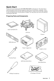
... Tools and Components Intel® LGA1200 CPU CPU Fan DDR4 Memory Power Supply Unit Chassis Graphics Card Thermal Paste SATA Hard Disk Drive SATA DVD Drive Phillips Screwdriver A Package of the installations also provide video demonstrations. This Quick Start section provides demonstration diagrams about how to install your phone or tablet. You may have even link to watch it with the web browser on your computer. Please link to the URL...
... Tools and Components Intel® LGA1200 CPU CPU Fan DDR4 Memory Power Supply Unit Chassis Graphics Card Thermal Paste SATA Hard Disk Drive SATA DVD Drive Phillips Screwdriver A Package of the installations also provide video demonstrations. This Quick Start section provides demonstration diagrams about how to install your phone or tablet. You may have even link to watch it with the web browser on your computer. Please link to the URL...

User Manual
Page 13
... a Processor 4 Installing DDR4 memory 5 Connecting the Front Panel Header 6 Installing the Motherboard 7 Connecting the Power Connectors 8 Installing SATA Drives 9 Installing a Graphics Card 10 Connecting Peripheral Devices 11 Power On...12 Specifications...16 JCORSAIR1 Connector Specification 23 Package contents 24 Block Diagram ...25 Rear I/O Panel...26 LAN Port LED Status Table 26 Audio Ports Configuration 26 Realtek Audio Console 27 Installing Antennas 29 Overview of Components 30 CPU Socket...32 DIMM Slots...33 PCI_E1~4: PCIe Expansion Slots 34 M2_1~4: M.2 Slots (Key M 36...
... a Processor 4 Installing DDR4 memory 5 Connecting the Front Panel Header 6 Installing the Motherboard 7 Connecting the Power Connectors 8 Installing SATA Drives 9 Installing a Graphics Card 10 Connecting Peripheral Devices 11 Power On...12 Specifications...16 JCORSAIR1 Connector Specification 23 Package contents 24 Block Diagram ...25 Rear I/O Panel...26 LAN Port LED Status Table 26 Audio Ports Configuration 26 Realtek Audio Console 27 Installing Antennas 29 Overview of Components 30 CPU Socket...32 DIMM Slots...33 PCI_E1~4: PCIe Expansion Slots 34 M2_1~4: M.2 Slots (Key M 36...
User Manual
Page 14
...-BIOS Switch 48 JRGB1: RGB LED connector 49 JRAINBOW1~2: Addressable RGB LED connectors 50 JCORSAIR1: CORSAIR Connector 51 Onboard LEDs...52 EZ Debug LED...52 XMP LED...52 Debug Code LED...52 Hexadecimal Character Table 53 Boot Phases...53 Debug Code LED Table 53 ACPI States Codes 57 CPU Temperature 57 Installing OS, Drivers & MSI Center 58 Installing Windows® 10 58 Installing Drivers 58 MSI Center...58 UEFI BIOS...59 BIOS Setup...60 Entering BIOS Setup 60 BIOS User Guide...60 Resetting BIOS...61 Updating BIOS...61 Nahimic 3...63 Installation and Update 63 Audio...
...-BIOS Switch 48 JRGB1: RGB LED connector 49 JRAINBOW1~2: Addressable RGB LED connectors 50 JCORSAIR1: CORSAIR Connector 51 Onboard LEDs...52 EZ Debug LED...52 XMP LED...52 Debug Code LED...52 Hexadecimal Character Table 53 Boot Phases...53 Debug Code LED Table 53 ACPI States Codes 57 CPU Temperature 57 Installing OS, Drivers & MSI Center 58 Installing Windows® 10 58 Installing Drivers 58 MSI Center...58 UEFI BIOS...59 BIOS Setup...60 Entering BIOS Setup 60 BIOS User Guide...60 Resetting BIOS...61 Updating BIOS...61 Nahimic 3...63 Installation and Update 63 Audio...
User Manual
Page 17
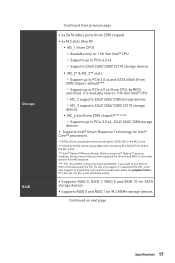
Before using Intel® Optane™ memory modules, please ensure that you have updated the drivers and BIOS to the latest version from Z590 chipset)***/ **** ▫▫Supports up to PCIe 3.0 x4, 2242/ 2260/ 2280 storage devices ∙∙ Supports Intel® Smart Response Technology for M.2 NVMe storage devices Continued on next page Specifications 17 Storage RAID Continued from previous page ∙∙6x SATA 6Gb/s ports (from Z590 chipset) ∙∙4x M.2 slots (Key M) ▪▪...
Before using Intel® Optane™ memory modules, please ensure that you have updated the drivers and BIOS to the latest version from Z590 chipset)***/ **** ▫▫Supports up to PCIe 3.0 x4, 2242/ 2260/ 2280 storage devices ∙∙ Supports Intel® Smart Response Technology for M.2 NVMe storage devices Continued on next page Specifications 17 Storage RAID Continued from previous page ∙∙6x SATA 6Gb/s ports (from Z590 chipset) ∙∙4x M.2 slots (Key M) ▪▪...

User Manual
Page 19
...pin ATX PCIE power connector ∙∙6x SATA 6Gb/s connectors ∙∙4x M.2 slots (M-Key) ∙∙1x USB 3.2 Gen 2 10Gbps Type-C port ∙∙1x USB 3.2 Gen 1 5Gbps connector (supports additional 2 USB 3.2 Gen 1 5Gbps ports) Internal Connectors ∙∙2x USB 2.0 connectors (supports additional 4 USB 2.0 ports) ∙∙1x 4-pin CPU fan connector ∙∙1x 4-pin water-pump fan connector ∙∙6x 4-pin system fan connectors ∙∙1x Front panel audio connector ∙∙2x System panel connectors ∙∙1x Chassis...
...pin ATX PCIE power connector ∙∙6x SATA 6Gb/s connectors ∙∙4x M.2 slots (M-Key) ∙∙1x USB 3.2 Gen 2 10Gbps Type-C port ∙∙1x USB 3.2 Gen 1 5Gbps connector (supports additional 2 USB 3.2 Gen 1 5Gbps ports) Internal Connectors ∙∙2x USB 2.0 connectors (supports additional 4 USB 2.0 ports) ∙∙1x 4-pin CPU fan connector ∙∙1x 4-pin water-pump fan connector ∙∙6x 4-pin system fan connectors ∙∙1x Front panel audio connector ∙∙2x System panel connectors ∙∙1x Chassis...

User Manual
Page 31
... 32 DIMM Slots 33 Front Audio Connector 39 Clear CMOS Jumper 48 Chassis Intrusion Connector 47 CORSAIR Connector 51 Tuning Controller connector 43 Front Panel Connectors 39 Low Temperature Booting Jumper 41 Safe Boot Jumper 42 OC Retry Jumper 42 Addressable RGB LED connectors 50 RGB LED connector 49 Slow Mode Booting Jumper 41 Thunderbolt Add-on Card Connector 42 TPM Module Connector 45 USB 2.0 Connectors 45 USB 3.2 Gen 1 Connector 44 USB 3.2 Gen 2 Type-C Connector 44 M.2 Slots (Key M) 36 PCIe Expansion Slots 34 Power Button, Reset Button 47 SATA 6Gb...
... 32 DIMM Slots 33 Front Audio Connector 39 Clear CMOS Jumper 48 Chassis Intrusion Connector 47 CORSAIR Connector 51 Tuning Controller connector 43 Front Panel Connectors 39 Low Temperature Booting Jumper 41 Safe Boot Jumper 42 OC Retry Jumper 42 Addressable RGB LED connectors 50 RGB LED connector 49 Slow Mode Booting Jumper 41 Thunderbolt Add-on Card Connector 42 TPM Module Connector 45 USB 2.0 Connectors 45 USB 3.2 Gen 1 Connector 44 USB 3.2 Gen 2 Type-C Connector 44 M.2 Slots (Key M) 36 PCIe Expansion Slots 34 Power Button, Reset Button 47 SATA 6Gb...

User Manual
Page 32
... heatsink to enhance heat dissipation. ∙∙Whenever the CPU is not installed, always protect the CPU socket pins by inadequate operation beyond product specifications is the Pin 1 indicator. ⚠⚠Important ∙∙Always unplug the power cord from the power outlet before booting your system. ∙∙Overheating can tolerate overclocking. Before attempting to support overclocking. The golden triangle is not recommended. CPU Socket...
... heatsink to enhance heat dissipation. ∙∙Whenever the CPU is not installed, always protect the CPU socket pins by inadequate operation beyond product specifications is the Pin 1 indicator. ⚠⚠Important ∙∙Always unplug the power cord from the power outlet before booting your system. ∙∙Overheating can tolerate overclocking. Before attempting to support overclocking. The golden triangle is not recommended. CPU Socket...

User Manual
Page 42
...-on Thunderbolt I/O card. 2 16 1 15 1 TBT_Force_PWR 2 TBT_S0IX_Entry_REQ 3 TBT_CIO_Plug_Event# 4 TBT_S0IX_Entry_ACK 5 SLP_S3#_TBT 6 TBT_PSON_Override_N 7 SLP_S5#_TBT 8 No pin 9 Ground 10 SMBCLK_VSB 11 DG_PEWake 12 SMBDATA_VSB 13 TBT_RTD3_PWR_EN 14 Ground 15 TBT_Card_DET_R# 16 PD_IRQ# 42 Overview of Components Enabled Apply the BIOS default settings and lower PCIe (from CPU) mode. Normal (default) Boot with default settings and lower PCIe (from CPU) mode for Safe Boot JOC_RT1: OC Retry Jumper This jumper is used for Safe Boot.
...-on Thunderbolt I/O card. 2 16 1 15 1 TBT_Force_PWR 2 TBT_S0IX_Entry_REQ 3 TBT_CIO_Plug_Event# 4 TBT_S0IX_Entry_ACK 5 SLP_S3#_TBT 6 TBT_PSON_Override_N 7 SLP_S5#_TBT 8 No pin 9 Ground 10 SMBCLK_VSB 11 DG_PEWake 12 SMBDATA_VSB 13 TBT_RTD3_PWR_EN 14 Ground 15 TBT_Card_DET_R# 16 PD_IRQ# 42 Overview of Components Enabled Apply the BIOS default settings and lower PCIe (from CPU) mode. Normal (default) Boot with default settings and lower PCIe (from CPU) mode for Safe Boot JOC_RT1: OC Retry Jumper This jumper is used for Safe Boot.

User Manual
Page 48
... clear the CMOS memory. Red: BIOS B Multi-BIOS LED White: BIOS A (Default) BIOS_SW1 ⚠⚠Important Do not use the Multi-BIOS switch when system is booting up. 48 Overview of Components Remove the jumper cap from a battery located on the computer. BIOS_SW1: Multi-BIOS Switch This motherboard has two built-in operation. Plug the power cord and Power on the motherboard to default values 1. Keep Data (default) Clear CMOS/ Reset BIOS Resetting BIOS to save system configuration data. JBAT1: Clear CMOS (Reset BIOS) Jumper There is CMOS memory onboard...
... clear the CMOS memory. Red: BIOS B Multi-BIOS LED White: BIOS A (Default) BIOS_SW1 ⚠⚠Important Do not use the Multi-BIOS switch when system is booting up. 48 Overview of Components Remove the jumper cap from a battery located on the computer. BIOS_SW1: Multi-BIOS Switch This motherboard has two built-in operation. Plug the power cord and Power on the motherboard to default values 1. Keep Data (default) Clear CMOS/ Reset BIOS Resetting BIOS to save system configuration data. JBAT1: Clear CMOS (Reset BIOS) Jumper There is CMOS memory onboard...

User Manual
Page 50
... JRAINBOW connector provide different voltages, and connecting the 5V LED strip to the JRGB connector will result in damage to the LED strip. ⚠⚠Important ∙∙The JRAINBOW connector supports up to 200 LEDs. ∙∙Always turn off the power supply and unplug the power cord from the power outlet before installing or removing the RGB LED strip. ∙∙Please use MSI's software to 75 LEDs WS2812B...
... JRAINBOW connector provide different voltages, and connecting the 5V LED strip to the JRGB connector will result in damage to the LED strip. ⚠⚠Important ∙∙The JRAINBOW connector supports up to 200 LEDs. ∙∙Always turn off the power supply and unplug the power cord from the power outlet before installing or removing the RGB LED strip. ∙∙Please use MSI's software to 75 LEDs WS2812B...

User Manual
Page 53
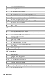
... is started Pre-memory PCH initialization (PCH module specific) Memory initialization. Memory presence detection Memory initialization. main hardware initialization Boot Device Selection (BDS) - system setup, pre-OS user interface & selecting a bootable device (CD/DVD, HDD, USB, Network, Shell, ...) Debug Code LED Table SEC Progress Codes 01 Power on. Hexadecimal Character Table Hexadecimal 0 1 2 3 4 5 6 7 8 9 A B C D E F Debug Code LED display 0123456789ABCDEF Boot Phases Security (SEC) - memory initialization Driver Execution Environment (DXE) - Serial Presence...
... is started Pre-memory PCH initialization (PCH module specific) Memory initialization. Memory presence detection Memory initialization. main hardware initialization Boot Device Selection (BDS) - system setup, pre-OS user interface & selecting a bootable device (CD/DVD, HDD, USB, Network, Shell, ...) Debug Code LED Table SEC Progress Codes 01 Power on. Hexadecimal Character Table Hexadecimal 0 1 2 3 4 5 6 7 8 9 A B C D E F Debug Code LED display 0123456789ABCDEF Boot Phases Security (SEC) - memory initialization Driver Execution Environment (DXE) - Serial Presence...
User Manual
Page 54
Configuring memory Memory initialization (other) Memory Installed CPU post-memory initialization is started 54 Onboard LEDs Cache initialization CPU post-memory initialization. Invalid memory type or incompatible memory speed Memory initialization error. Boot Strap Processor (BSP) selection CPU post-memory initialization. No usable memory detected Unspecified memory initialization error Memory not installed Invalid CPU type or Speed CPU mismatch CPU self test failed or possible CPU cache error CPU micro-code is not found or micro-code update is failed Internal CPU error Reset PPI is not ...
Configuring memory Memory initialization (other) Memory Installed CPU post-memory initialization is started 54 Onboard LEDs Cache initialization CPU post-memory initialization. Invalid memory type or incompatible memory speed Memory initialization error. Boot Strap Processor (BSP) selection CPU post-memory initialization. No usable memory detected Unspecified memory initialization error Memory not installed Invalid CPU type or Speed CPU mismatch CPU self test failed or possible CPU cache error CPU micro-code is not found or micro-code update is failed Internal CPU error Reset PPI is not ...
User Manual
Page 55
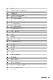
... Resources PCI Bus Assign Resources Console Output devices connect Console input devices connect Super IO Initialization USB initialization is started USB Reset USB Detect USB Enable Reserved for future AMI codes IDE initialization is started IDE Reset IDE Detect IDE Enable SCSI initialization is started SCSI Reset SCSI Detect SCSI Enable Setup Verifying Password Start of Setup Setup Input Wait Ready To Boot event Legacy Boot event Exit Boot Services event Runtime Set Virtual Address MAP Begin Runtime Set Virtual Address MAP End Legacy Option ROM Initialization System Reset Onboard LEDs 55
... Resources PCI Bus Assign Resources Console Output devices connect Console input devices connect Super IO Initialization USB initialization is started USB Reset USB Detect USB Enable Reserved for future AMI codes IDE initialization is started IDE Reset IDE Detect IDE Enable SCSI initialization is started SCSI Reset SCSI Detect SCSI Enable Setup Verifying Password Start of Setup Setup Input Wait Ready To Boot event Legacy Boot event Exit Boot Services event Runtime Set Virtual Address MAP Begin Runtime Set Virtual Address MAP End Legacy Option ROM Initialization System Reset Onboard LEDs 55
User Manual
Page 56
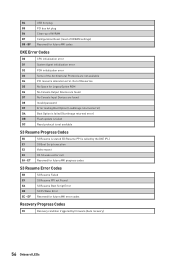
BF USB hot plug PCI bus hot plug Clean-up of NVRAM Configuration Reset (reset of the Architectural Protocols are found D8 Invalid password D9 Error loading Boot Option (LoadImage returned error) DA Boot Option is failed (StartImage returned error) DB Flash update is failed DC Reset protocol is called by firmware (Auto recovery) 56 Onboard LEDs E7 S3 Resume is stared (S3 Resume PPI is not available S3 Resume Progress Codes E0 E1 E2 E3 E4...
BF USB hot plug PCI bus hot plug Clean-up of NVRAM Configuration Reset (reset of the Architectural Protocols are found D8 Invalid password D9 Error loading Boot Option (LoadImage returned error) DA Boot Option is failed (StartImage returned error) DB Flash update is failed DC Reset protocol is called by firmware (Auto recovery) 56 Onboard LEDs E7 S3 Resume is stared (S3 Resume PPI is not available S3 Resume Progress Codes E0 E1 E2 E3 E4...
User Manual
Page 58
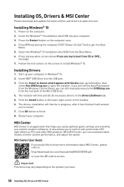
... MSI® USB Drive into Boot Menu. 5. If you turn off the AutoPlay feature from the Windows Control Panel, you have. 58 Installing OS, Drivers & MSI Center Insert the Windows® 10 installation disc/USB into your computer. MSI Center User Guide If you would like to know more information about MSI Center, please refer to http://download.msi.com/manual/mb/MSICENTER.pdf or scan the QR code to get into the USB port. 3. Power on...
... MSI® USB Drive into Boot Menu. 5. If you turn off the AutoPlay feature from the Windows Control Panel, you have. 58 Installing OS, Drivers & MSI Center Insert the Windows® 10 installation disc/USB into your computer. MSI Center User Guide If you would like to know more information about MSI Center, please refer to http://download.msi.com/manual/mb/MSICENTER.pdf or scan the QR code to get into the USB port. 3. Power on...
User Manual
Page 61
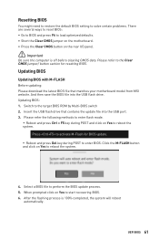
... automatically. After the flashing process is off before clearing CMOS data. Insert the USB flash drive that matches your motherboard model from MSI website. Resetting BIOS You might need to restore the default BIOS setting to solve certain problems. There are several ways to reset BIOS: ∙∙Go to BIOS and press F6 to load optimized defaults. ∙∙Short the Clear CMOS jumper on the motherboard. ∙∙Press the Clear CMOS button on Yes to...
... automatically. After the flashing process is off before clearing CMOS data. Insert the USB flash drive that matches your motherboard model from MSI website. Resetting BIOS You might need to restore the default BIOS setting to solve certain problems. There are several ways to reset BIOS: ∙∙Go to BIOS and press F6 to load optimized defaults. ∙∙Short the Clear CMOS jumper on the motherboard. ∙∙Press the Clear CMOS button on Yes to...

User Manual
Page 62
... to flash BIOS, and the LED starts flashing. 6. The system will restart automatically. Connect the power supply to CPU_PWR1 and ATX_PWR1. (No need to update BIOS. 6. To update BIOS: 1. The LED will be turned off when the process is 100% completed, the system will automatically restart to install CPU and memory.) 4. Rename the BIOS file to the root of the USB 2.0 storage device. 3. Updating the BIOS with Flash BIOS Button 1. Plug the USB 2.0 storage device that matches your motherboard model from the MSI®...
... to flash BIOS, and the LED starts flashing. 6. The system will restart automatically. Connect the power supply to CPU_PWR1 and ATX_PWR1. (No need to update BIOS. 6. To update BIOS: 1. The LED will be turned off when the process is 100% completed, the system will automatically restart to install CPU and memory.) 4. Rename the BIOS file to the root of the USB 2.0 storage device. 3. Updating the BIOS with Flash BIOS Button 1. Plug the USB 2.0 storage device that matches your motherboard model from the MSI®...
User Manual
Page 63
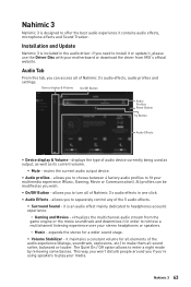
... audio device currently being used as output, as well as you wish. ∙∙ On/Off Button - virtualizes the multichannel audio stream from MSI's official website. displays the type of Nahimic 3's audio effects, audio profiles and settings. Installation and Update Nahimic 3 is an audio effect mainly dedicated to fit your media. expands the stereo for all elements of the audio experience (dialogs, soundtrack, explosions, etc.) to turn all sound...
... audio device currently being used as output, as well as you wish. ∙∙ On/Off Button - virtualizes the multichannel audio stream from MSI's official website. displays the type of Nahimic 3's audio effects, audio profiles and settings. Installation and Update Nahimic 3 is an audio effect mainly dedicated to fit your media. expands the stereo for all elements of the audio experience (dialogs, soundtrack, explosions, etc.) to turn all sound...

User Manual
Page 68
... over troubleshooting guide first to install only one memory module in the BIOS. The computer does not boot after updating the BIOS ∙∙Clear the CMOS. ∙∙Use the secondary BIOS to bootup the system (Only for RMA repair, try to see if your router. ∙∙Test with another known working LAN cable. The power is turned on the motherboard rear IO panel. ∙∙Remove secondary speakers/ headphones, HDMI cables, USB audio devices...
... over troubleshooting guide first to install only one memory module in the BIOS. The computer does not boot after updating the BIOS ∙∙Clear the CMOS. ∙∙Use the secondary BIOS to bootup the system (Only for RMA repair, try to see if your router. ∙∙Test with another known working LAN cable. The power is turned on the motherboard rear IO panel. ∙∙Remove secondary speakers/ headphones, HDMI cables, USB audio devices...
User Manual
Page 72
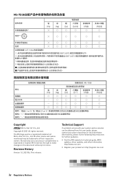
... help resources for technical guide, BIOS updates, driver updates, and other marks and names mentioned may be obtained from the user guide, please contact your product at: http://register.msi.com iv Regulatory Notices Copyright © 2021 All rights reserved. The MSI logo used is expressed or implied. yy Visit the MSI website for further guidance. Technical Support If a problem arises with your system...
... help resources for technical guide, BIOS updates, driver updates, and other marks and names mentioned may be obtained from the user guide, please contact your product at: http://register.msi.com iv Regulatory Notices Copyright © 2021 All rights reserved. The MSI logo used is expressed or implied. yy Visit the MSI website for further guidance. Technical Support If a problem arises with your system...


