
User Manual
Page 12
... a Processor 3 Installing DDR4 memory 4 Connecting the Front Panel Header 5 Installing the Motherboard 6 Connecting the Power Connectors 7 Installing SATA Drives 8 Installing a Graphics Card 9 Connecting Peripheral Devices 10 Power On...11 Specifications...15 JCORSAIR1 Connector Specification 20 Package contents 20 Block Diagram ...21 Rear I/O Panel...22 LAN Port LED Status Table 22 Audio Ports Configuration 22 Realtek Audio Console 23 Installing Antennas 25 Overview of Components 26 CPU Socket...28 DIMM Slots...29 PCI_E1~5: PCIe Expansion Slots 30 M2_1~3: M.2 Slots (Key M 32...
... a Processor 3 Installing DDR4 memory 4 Connecting the Front Panel Header 5 Installing the Motherboard 6 Connecting the Power Connectors 7 Installing SATA Drives 8 Installing a Graphics Card 9 Connecting Peripheral Devices 10 Power On...11 Specifications...15 JCORSAIR1 Connector Specification 20 Package contents 20 Block Diagram ...21 Rear I/O Panel...22 LAN Port LED Status Table 22 Audio Ports Configuration 22 Realtek Audio Console 23 Installing Antennas 25 Overview of Components 26 CPU Socket...28 DIMM Slots...29 PCI_E1~5: PCIe Expansion Slots 30 M2_1~3: M.2 Slots (Key M 32...

User Manual
Page 13
... RGB LED connectors 48 JCORSAIR1: CORSAIR Connector 49 Onboard LEDs...50 EZ Debug LED...50 XMP LED...50 JPWRLED1: LED power input 50 LED_SW1: EZ LED Control 51 Debug Code LED...51 Hexadecimal Character Table 51 Boot Phases...51 Debug Code LED Table 52 ACPI States Codes 56 CPU Temperature 56 Installing OS, Drivers & Utilities 57 Installing Windows® 10 57 Installing Drivers 57 Installing Utilities 57 UEFI BIOS...58 BIOS Setup...59 Entering BIOS Setup 59 Resetting BIOS...60 Updating BIOS...60 EZ Mode...62 Advanced Mode ...66 SETTINGS Menu...67 OC Menu...69 M-FLASH Menu...
... RGB LED connectors 48 JCORSAIR1: CORSAIR Connector 49 Onboard LEDs...50 EZ Debug LED...50 XMP LED...50 JPWRLED1: LED power input 50 LED_SW1: EZ LED Control 51 Debug Code LED...51 Hexadecimal Character Table 51 Boot Phases...51 Debug Code LED Table 52 ACPI States Codes 56 CPU Temperature 56 Installing OS, Drivers & Utilities 57 Installing Windows® 10 57 Installing Drivers 57 Installing Utilities 57 UEFI BIOS...58 BIOS Setup...59 Entering BIOS Setup 59 Resetting BIOS...60 Updating BIOS...60 EZ Mode...62 Advanced Mode ...66 SETTINGS Menu...67 OC Menu...69 M-FLASH Menu...
User Manual
Page 14
Installation and Update 77 Audio Tab...77 Microphone Tab...78 Sound Tracker Tab 79 Settings Tab...79 RAID Configuration 80 Enabling Intel® Rapid Storage Technology 80 Creating RAID Volume 81 Removing a RAID Volume 82 Resetting Disks to Non-RAID 83 Rebuilding RAID Array 84 Installing RAID Driver 85 Installing Intel® Rapid Storage Technology Software 85 Intel® Optane™ Memory Configuration 86 System Requirements 86 Installing the Intel® Optane™ memory 86 Removing the Intel® Optane™ memory 88 Troubleshooting 89 14 Contents
Installation and Update 77 Audio Tab...77 Microphone Tab...78 Sound Tracker Tab 79 Settings Tab...79 RAID Configuration 80 Enabling Intel® Rapid Storage Technology 80 Creating RAID Volume 81 Removing a RAID Volume 82 Resetting Disks to Non-RAID 83 Rebuilding RAID Array 84 Installing RAID Driver 85 Installing Intel® Rapid Storage Technology Software 85 Intel® Optane™ Memory Configuration 86 System Requirements 86 Installing the Intel® Optane™ memory 86 Removing the Intel® Optane™ memory 88 Troubleshooting 89 14 Contents
User Manual
Page 20
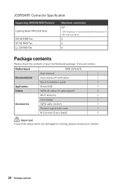
... Connector Specification Supporting CORSAIR RGB Products Lighting Node PRO LED Strip HD120 RGB Fan SP120 RGB Fan LL120 RGB Fan Maximum connection 20* * 20% brightness is recommended when the number of LED strips exceeds 8. 6 6 6 Package contents Please check the contents of the above items are damaged or missing, please contact your motherboard package. It should contain: Motherboard MEG Z490 ACE User manual 1 Documentation Case stand-off notification 1 Quick installation guide 1 Application Driver DVD 1 Cables SATA...
... Connector Specification Supporting CORSAIR RGB Products Lighting Node PRO LED Strip HD120 RGB Fan SP120 RGB Fan LL120 RGB Fan Maximum connection 20* * 20% brightness is recommended when the number of LED strips exceeds 8. 6 6 6 Package contents Please check the contents of the above items are damaged or missing, please contact your motherboard package. It should contain: Motherboard MEG Z490 ACE User manual 1 Documentation Case stand-off notification 1 Quick installation guide 1 Application Driver DVD 1 Cables SATA...

User Manual
Page 48
... JRAINBOW connector provide different voltages, and connecting the 5V LED strip to the JRGB connector will result in damage to the LED strip. ⚠⚠Important ∙∙The JRAINBOW connector supports up to 200 LEDs. ∙∙Always turn off the power supply and unplug the power cord from the power outlet before installing or removing the RGB LED strip. ∙∙Please use MSI's software to 75 LEDs WS2812B...
... JRAINBOW connector provide different voltages, and connecting the 5V LED strip to the JRGB connector will result in damage to the LED strip. ⚠⚠Important ∙∙The JRAINBOW connector supports up to 200 LEDs. ∙∙Always turn off the power supply and unplug the power cord from the power outlet before installing or removing the RGB LED strip. ∙∙Please use MSI's software to 75 LEDs WS2812B...

User Manual
Page 52
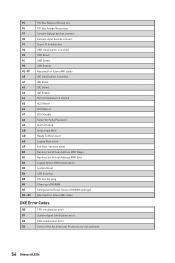
... Codes 01 Power on. Boot Strap Processor (BSP) selection CPU post-memory initialization. Application Processor(s) (AP) initialization CPU post-memory initialization. Memory presence detection Memory initialization. Serial Presence Detect (SPD) data reading Memory initialization. Configuring memory Memory initialization (other) Memory Installed CPU post-memory initialization is started 52 Onboard LEDs System Management Mode (SMM) initialization Post-Memory System Agent initialization is started Post-Memory System Agent initialization (System Agent module specific) Post-Memory...
... Codes 01 Power on. Boot Strap Processor (BSP) selection CPU post-memory initialization. Application Processor(s) (AP) initialization CPU post-memory initialization. Memory presence detection Memory initialization. Serial Presence Detect (SPD) data reading Memory initialization. Configuring memory Memory initialization (other) Memory Installed CPU post-memory initialization is started 52 Onboard LEDs System Management Mode (SMM) initialization Post-Memory System Agent initialization is started Post-Memory System Agent initialization (System Agent module specific) Post-Memory...

User Manual
Page 53
... initialization is started System Agent DXE initialization (System Agent module specific) PCH DXE initialization is started PCH DXE SMM initialization is started PCH devices initialization PCH DXE Initialization (PCH module specific) ACPI module initialization CSM initialization Reserved for future AMI DXE codes Boot Device Selection (BDS) phase is started Driver connecting is started PCI Bus initialization is started PCI Bus Hot Plug Controller Initialization PCI Bus Enumeration 32 Onboard LEDs 53 Invalid memory type or incompatible memory speed Memory initialization error.
... initialization is started System Agent DXE initialization (System Agent module specific) PCH DXE initialization is started PCH DXE SMM initialization is started PCH devices initialization PCH DXE Initialization (PCH module specific) ACPI module initialization CSM initialization Reserved for future AMI DXE codes Boot Device Selection (BDS) phase is started Driver connecting is started PCI Bus initialization is started PCI Bus Hot Plug Controller Initialization PCI Bus Enumeration 32 Onboard LEDs 53 Invalid memory type or incompatible memory speed Memory initialization error.
User Manual
Page 54
...USB initialization is started USB Reset USB Detect USB Enable Reserved for future AMI codes IDE initialization is started IDE Reset IDE Detect IDE Enable SCSI initialization is started SCSI Reset SCSI Detect SCSI Enable Setup Verifying Password Start of Setup Setup Input Wait Ready To Boot event Legacy Boot event Exit Boot Services event Runtime Set Virtual Address MAP Begin Runtime Set Virtual Address MAP End Legacy Option ROM Initialization System Reset USB hot plug PCI bus hot plug Clean-up of NVRAM Configuration Reset (reset of NVRAM settings) Reserved for future AMI codes DXE Error Codes...
...USB initialization is started USB Reset USB Detect USB Enable Reserved for future AMI codes IDE initialization is started IDE Reset IDE Detect IDE Enable SCSI initialization is started SCSI Reset SCSI Detect SCSI Enable Setup Verifying Password Start of Setup Setup Input Wait Ready To Boot event Legacy Boot event Exit Boot Services event Runtime Set Virtual Address MAP Begin Runtime Set Virtual Address MAP End Legacy Option ROM Initialization System Reset USB hot plug PCI bus hot plug Clean-up of NVRAM Configuration Reset (reset of NVRAM settings) Reserved for future AMI codes DXE Error Codes...
User Manual
Page 57
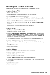
... button to finish. 8. Press F11 key during the computer POST (Power-On Self Test) to choose what happens with this disc pop-up your computer. If you turn off the AutoPlay feature from the Windows Control Panel, you can still manually execute the DVDSetup.exe from the root path of the MSI USB Drive. 4. Installing OS, Drivers & Utilities Please download and update the latest utilities and drivers at www.msi...
... button to finish. 8. Press F11 key during the computer POST (Power-On Self Test) to choose what happens with this disc pop-up your computer. If you turn off the AutoPlay feature from the Windows Control Panel, you can still manually execute the DVDSetup.exe from the root path of the MSI USB Drive. 4. Installing OS, Drivers & Utilities Please download and update the latest utilities and drivers at www.msi...

User Manual
Page 60
.... Updating BIOS: 1. Insert the USB flash drive that matches your motherboard model from MSI website. Click on Yes to reboot the system. 3. Press to activate M-Flash for resetting BIOS. Resetting BIOS You might need to restore the default BIOS setting to solve certain problems. There are several ways to reset BIOS: ∙∙Go to BIOS and press F6 to load optimized defaults. ∙∙Short the Clear CMOS jumper on the motherboard. ∙∙Press the Clear CMOS button...
.... Updating BIOS: 1. Insert the USB flash drive that matches your motherboard model from MSI website. Click on Yes to reboot the system. 3. Press to activate M-Flash for resetting BIOS. Resetting BIOS You might need to restore the default BIOS setting to solve certain problems. There are several ways to reset BIOS: ∙∙Go to BIOS and press F6 to load optimized defaults. ∙∙Short the Clear CMOS jumper on the motherboard. ∙∙Press the Clear CMOS button...

User Manual
Page 61
Select Live Update and click on Scan button to the root of your motherboard model from the MSI® website. 2. Select the BIOS file and click on Download icon to flash BIOS, and the LED starts flashing. 6. Press the Flash BIOS Button to download and install the latest BIOS file. 5. Click on the rear I/O panel. 5. And then click Next and Start to achieve by reset button. Plug the USB flash drive that matches your USB flash drive. 3. UEFI BIOS 61 Connect the power supply to CPU_PWR1 and...
Select Live Update and click on Scan button to the root of your motherboard model from the MSI® website. 2. Select the BIOS file and click on Download icon to flash BIOS, and the LED starts flashing. 6. Press the Flash BIOS Button to download and install the latest BIOS file. 5. Click on the rear I/O panel. 5. And then click Next and Start to achieve by reset button. Plug the USB flash drive that matches your USB flash drive. 3. UEFI BIOS 61 Connect the power supply to CPU_PWR1 and...

User Manual
Page 63
... CPU/ DDR speed, CPU/ MB temperature, MB/ CPU type, memory size, CPU/ DDR voltage, BIOS version and build date. ∙∙ Boot device priority bar - you can move the device icons to change and select Yes to operate full speed or default speeds. ▪▪Configuring Smart Button 1. click on Smart Button and select a function mode. 2. press the reset button to turn on/ off all fans to restart the system. ∙∙ Language - allows you purchased. The boot priority from high...
... CPU/ DDR speed, CPU/ MB temperature, MB/ CPU type, memory size, CPU/ DDR voltage, BIOS version and build date. ∙∙ Boot device priority bar - you can move the device icons to change and select Yes to operate full speed or default speeds. ▪▪Configuring Smart Button 1. click on Smart Button and select a function mode. 2. press the reset button to turn on/ off all fans to restart the system. ∙∙ Language - allows you purchased. The boot priority from high...

User Manual
Page 67
... of onboard power LED behaviors. ▶▶Integrated Peripherals sub-menu Sets integrated peripherals' parameters, such as LAN, Wi-Fi, HDD, SSD, USB and audio. Read-only. The format is not displayed, turn off computer and re-check SATA/ M.2 cable and power cable connections of the device and motherboard. ▶▶System Information Shows detailed system information, including CPU type, BIOS version, and Memory (read only). ▶▶DMI Information Shows system information, desktop Board...
... of onboard power LED behaviors. ▶▶Integrated Peripherals sub-menu Sets integrated peripherals' parameters, such as LAN, Wi-Fi, HDD, SSD, USB and audio. Read-only. The format is not displayed, turn off computer and re-check SATA/ M.2 cable and power cable connections of the device and motherboard. ▶▶System Information Shows detailed system information, including CPU type, BIOS version, and Memory (read only). ▶▶DMI Information Shows system information, desktop Board...

User Manual
Page 68
... being disabled. Type the password then press Enter. You may also press Esc key to enter the sub-menu. ▶▶Power Management Setup sub-menu Sets system Power Management of system boot devices. ▶▶Security sub-menu Use this menu. ▶▶Wake Up Event Setup sub-menu Sets system wake up behaviors for system security. This sub-menu is only available when using the Intel thunderbolt device. ▶▶USB Configuration sub-menu Sets the onboard USB controller and device...
... being disabled. Type the password then press Enter. You may also press Esc key to enter the sub-menu. ▶▶Power Management Setup sub-menu Sets system Power Management of system boot devices. ▶▶Security sub-menu Use this menu. ▶▶Wake Up Event Setup sub-menu Sets system wake up behaviors for system security. This sub-menu is only available when using the Intel thunderbolt device. ▶▶USB Configuration sub-menu Sets the onboard USB controller and device...
User Manual
Page 70
... a CPU that overclocking behavior and stability is installed. ▶▶CPU Base Clock Apply Mode [Auto]* Sets the applying mode for adjusted CPU base clock. [Auto] This setting will be changed dynamically according to the CPU loading. ▶▶CPU Ratio Offset When Running AVX [Auto] Sets a offset value to CPU features. ▶▶CPU Base Clock (MHz) [Default] Sets the CPU Base clock. These items only appear when CPU Ratio Apply Mode set the CPU ratio manually. [Fixed Mode] [Dynamic Mode] Fixes...
... a CPU that overclocking behavior and stability is installed. ▶▶CPU Base Clock Apply Mode [Auto]* Sets the applying mode for adjusted CPU base clock. [Auto] This setting will be changed dynamically according to the CPU loading. ▶▶CPU Ratio Offset When Running AVX [Auto] Sets a offset value to CPU features. ▶▶CPU Base Clock (MHz) [Default] Sets the CPU Base clock. These items only appear when CPU Ratio Apply Mode set the CPU ratio manually. [Fixed Mode] [Dynamic Mode] Fixes...
User Manual
Page 71
...) [Disabled] XMP (Extreme Memory Profile) is the overclocking technology by choosing optimized memory preset. ▶▶DRAM Timing Mode [Link] Selects the memory timing mode. [Link] Allows user to configure the DRAM timing for all memory channel. If it occurs, please clear the CMOS data and restore the default settings. (Refer to the Clear CMOS jumper/ button section to clear the CMOS data, and enter the BIOS to enter the sub-menu. Read-only. ▶▶Load Memory Presets [Disabled]* Load OC Memory...
...) [Disabled] XMP (Extreme Memory Profile) is the overclocking technology by choosing optimized memory preset. ▶▶DRAM Timing Mode [Link] Selects the memory timing mode. [Link] Allows user to configure the DRAM timing for all memory channel. If it occurs, please clear the CMOS data and restore the default settings. (Refer to the Clear CMOS jumper/ button section to clear the CMOS data, and enter the BIOS to enter the sub-menu. Read-only. ▶▶Load Memory Presets [Disabled]* Load OC Memory...
User Manual
Page 77
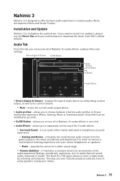
... turn all of audio device currently being used as output, as well as you wish. ∙∙ On/Off Button - Nahimic 3 77 mutes the current audio output device. ∙∙ Audio profiles - it is an audio effect mainly dedicated to enter a night mode by removing some basses. allows you to choose between 4 factory audio profiles to install it or update it in order to separately control any...
... turn all of audio device currently being used as output, as well as you wish. ∙∙ On/Off Button - Nahimic 3 77 mutes the current audio output device. ∙∙ Audio profiles - it is an audio effect mainly dedicated to enter a night mode by removing some basses. allows you to choose between 4 factory audio profiles to install it or update it in order to separately control any...
User Manual
Page 85
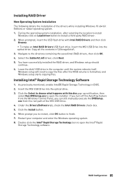
... successfully installed the RAID driver, and Windows setup should continue. 6. RAID Configuration 85 If you turn off the AutoPlay feature from the root path of the drivers while installing Windows 10 x64 bit Editions or newer operating system. 1. Leave the disk/ USB drive in \\Storage\Intel\ 3. exe from the Windows Control Panel, you to restart, click OK button to open the Intel® Rapid Storage Technology software. Insert the MSI USB Drive into the optical drive. Double...
... successfully installed the RAID driver, and Windows setup should continue. 6. RAID Configuration 85 If you turn off the AutoPlay feature from the root path of the drivers while installing Windows 10 x64 bit Editions or newer operating system. 1. Leave the disk/ USB drive in \\Storage\Intel\ 3. exe from the Windows Control Panel, you to restart, click OK button to open the Intel® Rapid Storage Technology software. Insert the MSI USB Drive into the optical drive. Double...
User Manual
Page 86
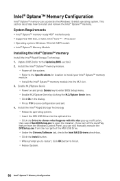
...; Optane™ Memory Configuration Intel® Optane™ memory can still manually execute the DVDSetup.exe from the Windows Control Panel, you can accelerate the Windows 10 64bit operating system. Install the Intel® Rapid Storage Technology ▫▫Reboot to operating system. ▫▫Insert the MSI USB Drive into the M.2 slot. 3. Update BIOS (refer to open the installer. i Processor ∙∙Operating system: Windows 10 64 bit (UEFI mode). ∙∙...
...; Optane™ Memory Configuration Intel® Optane™ memory can still manually execute the DVDSetup.exe from the Windows Control Panel, you can accelerate the Windows 10 64bit operating system. Install the Intel® Rapid Storage Technology ▫▫Reboot to operating system. ▫▫Insert the MSI USB Drive into the M.2 slot. 3. Update BIOS (refer to open the installer. i Processor ∙∙Operating system: Windows 10 64 bit (UEFI mode). ∙∙...

User Manual
Page 89
... working speaker or headphone. There is no network ∙∙Make sure the network chipset driver has been installed. ∙∙Verify if the network cable is properly connected and make sure the LAN port LEDs are connected from the power supply to the motherboard? ∙∙Some power supply units have a power button on the rear side, make sure the button is turned on. ∙∙Check if the power switch cable is connected to JFP1 pin header...
... working speaker or headphone. There is no network ∙∙Make sure the network chipset driver has been installed. ∙∙Verify if the network cable is properly connected and make sure the LAN port LEDs are connected from the power supply to the motherboard? ∙∙Some power supply units have a power button on the rear side, make sure the button is turned on. ∙∙Check if the power switch cable is connected to JFP1 pin header...


