User Manual
Page 1
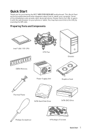
Quick Start Thank you for purchasing the MSI® MEG Z390 GODLIKE motherboard. This Quick Start section provides demonstration diagrams about how to install your phone or tablet. You may have even link to watch it with the ...
Quick Start Thank you for purchasing the MSI® MEG Z390 GODLIKE motherboard. This Quick Start section provides demonstration diagrams about how to install your phone or tablet. You may have even link to watch it with the ...

User Manual
Page 2
... from the power outlet before connecting the PSU to the electrical outlet. Please adhere to the following situations arises, get the motherboard checked by touching another metal object before installation is not available, discharge yourself of the following instructions to the user. y...Place the power cord such a way that your electrical outlet provides the same voltage as injury to ensure successful computer assembly. y Store the motherboard in an environment above 60°C (140°F), it . y Keep this user guide for future reference. y If any of static electricity...
... from the power outlet before connecting the PSU to the electrical outlet. Please adhere to the following situations arises, get the motherboard checked by touching another metal object before installation is not available, discharge yourself of the following instructions to the user. y...Place the power cord such a way that your electrical outlet provides the same voltage as injury to ensure successful computer assembly. y Store the motherboard in an environment above 60°C (140°F), it . y Keep this user guide for future reference. y If any of static electricity...

User Manual
Page 6
Installing the Motherboard 1 2 6 Safety Information
Installing the Motherboard 1 2 6 Safety Information
User Manual
Page 12
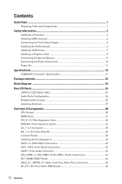
Contents Quick Start ...1 Preparing Tools and Components 1 Safety Information 2 Installing a Processor 3 Installing DDR4 memory 4 Connecting the Front Panel Header 5 Installing the Motherboard 6 Installing SATA Drives 7 Installing a Graphics Card 8 Connecting Peripheral Devices 9 Connecting the Power Connectors 10 Power On...11 Specifications...15 JCORSAIR1 Connector Specification 21 Package contents ...
Contents Quick Start ...1 Preparing Tools and Components 1 Safety Information 2 Installing a Processor 3 Installing DDR4 memory 4 Connecting the Front Panel Header 5 Installing the Motherboard 6 Installing SATA Drives 7 Installing a Graphics Card 8 Connecting Peripheral Devices 9 Connecting the Power Connectors 10 Power On...11 Specifications...15 JCORSAIR1 Connector Specification 21 Package contents ...
User Manual
Page 22
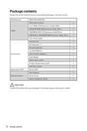
Package contents Please check the contents of the above items are damaged or missing, please contact your motherboard package. It should contain: Motherboard Cable Accessories Application DVD Documentation MEG Z390 GODLIKE SATA 6Gb/s Cables 6 1 to 2 RGB LED Extension Y Cable 80cm 1 CORSAIR RGB LED Extension Cable 50cm 1 RAINBOW RGB LED Extension Cable 80cm 2 CORSAIR to RAINBOW RGB...
Package contents Please check the contents of the above items are damaged or missing, please contact your motherboard package. It should contain: Motherboard Cable Accessories Application DVD Documentation MEG Z390 GODLIKE SATA 6Gb/s Cables 6 1 to 2 RGB LED Extension Y Cable 80cm 1 CORSAIR RGB LED Extension Cable 50cm 1 RAINBOW RGB LED Extension Cable 80cm 2 CORSAIR to RAINBOW RGB...

User Manual
Page 30
...layer of the LGA 1151 CPU has two notches and a golden triangle to assist in the heatsink/ cooler package for motherboard placement. y This motherboard is not installed, always protect the CPU socket pins by inadequate operation beyond product specifications is not recommended. Any attempt to... of thermal paste (or thermal tape) between the CPU and the heatsink to enhance heat dissipation. MSI will deal with Return Merchandise Authorization (RMA) requests if only the motherboard comes with the CPU before installing or removing the CPU. A CPU heatsink is the Pin 1 indicator...
...layer of the LGA 1151 CPU has two notches and a golden triangle to assist in the heatsink/ cooler package for motherboard placement. y This motherboard is not installed, always protect the CPU socket pins by inadequate operation beyond product specifications is not recommended. Any attempt to... of thermal paste (or thermal tape) between the CPU and the heatsink to enhance heat dissipation. MSI will deal with Return Merchandise Authorization (RMA) requests if only the motherboard comes with the CPU before installing or removing the CPU. A CPU heatsink is the Pin 1 indicator...
User Manual
Page 31
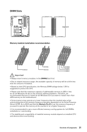
y The stability and compatibility of addressable memory is recommended to the memory frequency operates dependent on the motherboard. Therefore, we recommended that the maximum capacity of installed memory module depend on Intel CPU specification, the Memory DIMM voltage below 1.35V is suggested to ...
y The stability and compatibility of addressable memory is recommended to the memory frequency operates dependent on the motherboard. Therefore, we recommended that the maximum capacity of installed memory module depend on Intel CPU specification, the Memory DIMM voltage below 1.35V is suggested to ...

User Manual
Page 35
Connect the U.2 cable to Install U.2 SSD. Video Demonstration Watch the video to learn how to the U.2 connector on the motherboard. 2. Connect the U.2 cable to power adapter cable. U.2 SSD U.2 Connector 2 1 U.2 Cable 3 Connect to one PCIe 3.0 x4 NVMe storage device. Overview of Components 35 Connect the U.2 cable ...
Connect the U.2 cable to Install U.2 SSD. Video Demonstration Watch the video to learn how to the U.2 connector on the motherboard. 2. Connect the U.2 cable to power adapter cable. U.2 SSD U.2 Connector 2 1 U.2 Cable 3 Connect to one PCIe 3.0 x4 NVMe storage device. Overview of Components 35 Connect the U.2 cable ...

User Manual
Page 40
... in to PCI_E5 slot. 40 Overview of the cable. y SATA cables have identical plugs on either sides of Components Each connector can connect to the motherboard for space saving purposes.
... in to PCI_E5 slot. 40 Overview of the cable. y SATA cables have identical plugs on either sides of Components Each connector can connect to the motherboard for space saving purposes.
User Manual
Page 43
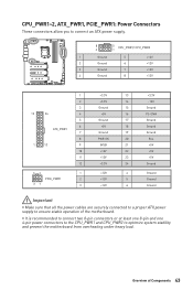
... Ground Ground Important y Make sure that all the power cables are securely connected to a proper ATX power supply to optimize system stability and prevent the motherboard from overheating under heavy load. y It is recommended to connect two 8-pin connectors or at least one 8-pin and one 4-pin power connectors to the...
... Ground Ground Important y Make sure that all the power cables are securely connected to a proper ATX power supply to optimize system stability and prevent the motherboard from overheating under heavy load. y It is recommended to connect two 8-pin connectors or at least one 8-pin and one 4-pin power connectors to the...
User Manual
Page 47
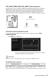
... mode or DC mode There are working properly after switching the PWM/ DC mode. Important Make sure fans are gradient points of Components 47 This motherboard can be classified as PWM (Pulse Width Modulation) Mode or DC Mode. CPU_FAN1, PUMP_FAN1, SYS_FAN1~8: Fan Connectors Fan connectors can automatically detect PWM and DC...
... mode or DC mode There are working properly after switching the PWM/ DC mode. Important Make sure fans are gradient points of Components 47 This motherboard can be classified as PWM (Pulse Width Modulation) Mode or DC Mode. CPU_FAN1, PUMP_FAN1, SYS_FAN1~8: Fan Connectors Fan connectors can automatically detect PWM and DC...

User Manual
Page 49
...connector is a charger port which can still charge your smartphone or USB-powered devices. Important When the Charging mode is hardware controlled by motherboard chip, it can increase USB power output for fast charging your device in suspend, hibernate state or even shutdown states. Overview of ...Components 49 The Charger Port is enabled, the Charger Port data syncing will need to install the MSI DRAGON CENTER software to turn ON/OFF the Charging mode. However, when you boot the computer into Windows®, you to connect USB...
...connector is a charger port which can still charge your smartphone or USB-powered devices. Important When the Charging mode is hardware controlled by motherboard chip, it can increase USB power output for fast charging your device in suspend, hibernate state or even shutdown states. Overview of ...Components 49 The Charger Port is enabled, the Charger Port data syncing will need to install the MSI DRAGON CENTER software to turn ON/OFF the Charging mode. However, when you boot the computer into Windows®, you to connect USB...

User Manual
Page 50
... Xpander Cable to 4 connectors. Connecting USB Xpander (optional) The USB Xpander is used to expand a single USB 2.0 connector to connect the expansion board and the motherboard as shown below. JUSB5~6: USB 2.0 Connectors 2 10 1 9 1 VCC 2 3 USB0- 4 5 USB0+ 6 7 Ground 8 9 No Pin 10 VCC USB1USB1+ ... Note that the VCC and Ground pins must be connected correctly to power adapter cable Triangle mark USB 2.0 connector on the motherboard 50 Overview of Components USB Xpander USB Xpander Cable Connect to avoid possible damage. y In order to recharge your iPad,iPhone...
... Xpander Cable to 4 connectors. Connecting USB Xpander (optional) The USB Xpander is used to expand a single USB 2.0 connector to connect the expansion board and the motherboard as shown below. JUSB5~6: USB 2.0 Connectors 2 10 1 9 1 VCC 2 3 USB0- 4 5 USB0+ 6 7 Ground 8 9 No Pin 10 VCC USB1USB1+ ... Note that the VCC and Ground pins must be connected correctly to power adapter cable Triangle mark USB 2.0 connector on the motherboard 50 Overview of Components USB Xpander USB Xpander Cable Connect to avoid possible damage. y In order to recharge your iPad,iPhone...
User Manual
Page 51
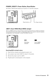
Remove the jumper cap from a battery located on the motherboard to save system configuration data. Plug the power cord and power on / reset the computer. Power off the computer and unplug the power cord 2. Use a ...
Remove the jumper cap from a battery located on the motherboard to save system configuration data. Plug the power cord and power on / reset the computer. Power off the computer and unplug the power cord 2. Use a ...
User Manual
Page 53
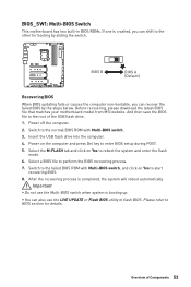
... the computer non-bootable, you can recover the failed BIOS by sliding the switch. Before recovering, please download the latest BIOS file that matches your motherboard model from MSI website. BIOS_SW1: Multi-BIOS Switch This motherboard has two built-in BIOS ROMs. If one is booting up.
... the computer non-bootable, you can recover the failed BIOS by sliding the switch. Before recovering, please download the latest BIOS file that matches your motherboard model from MSI website. BIOS_SW1: Multi-BIOS Switch This motherboard has two built-in BIOS ROMs. If one is booting up.

User Manual
Page 55
y Quantity of Components 55 Please refer to connect the CORSAIR Individually Addressable RGB LED strips 5V or CORSAIR RGB LED fans with MSI's software. JCORSAIR1 1 1 +5V 2 3 Ground Data CORSAIR RGB LED Fan Connection SATA power 3 2 1 CORSAIR fan hub 4 5 6 CORSAIR RGB LED fan CORSAIR RGB LED Extension Cable JCORSAIR1 ... RGB LED Lighting PRO strips supported may differ between models. Any fan not connected in series. 1 > 2 > 3 > 4 > 5 > 6. Once all items are connected properly, you to the motherboard specification.
y Quantity of Components 55 Please refer to connect the CORSAIR Individually Addressable RGB LED strips 5V or CORSAIR RGB LED fans with MSI's software. JCORSAIR1 1 1 +5V 2 3 Ground Data CORSAIR RGB LED Fan Connection SATA power 3 2 1 CORSAIR fan hub 4 5 6 CORSAIR RGB LED fan CORSAIR RGB LED Extension Cable JCORSAIR1 ... RGB LED Lighting PRO strips supported may differ between models. Any fan not connected in series. 1 > 2 > 3 > 4 > 5 > 6. Once all items are connected properly, you to the motherboard specification.

User Manual
Page 57
... SYS_FAN7 LED Onboard LEDs 57 indicates DRAM is not detected or fail. Onboard LEDs EZ Debug LED These LEDs indicate the debug status of the motherboard. indicates CPU is not detected or fail. CPU - VGA - DIMM LEDs Fan LEDs These LEDs indicate the fan control mode. BOOT -
... SYS_FAN7 LED Onboard LEDs 57 indicates DRAM is not detected or fail. Onboard LEDs EZ Debug LED These LEDs indicate the debug status of the motherboard. indicates CPU is not detected or fail. CPU - VGA - DIMM LEDs Fan LEDs These LEDs indicate the fan control mode. BOOT -
User Manual
Page 70
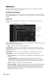
... y Device display & Volume - allows you need to install it or update it, please use the Driver Disc with your motherboard or download the driver from the game engine or the movie soundtrack and downmixes it in order to retrieve a multichannel listening experience... Surround Sound - displays the type of Nahimic 3's audio effects in the audio driver. y On/Off Button - virtualizes the multichannel audio stream from MSI's official website. Nahimic 3 Nahimic 3 is an audio effect mainly dedicated to headphones acoustic experience. ˜ Gaming and Movies - mutes the current audio...
... y Device display & Volume - allows you need to install it or update it, please use the Driver Disc with your motherboard or download the driver from the game engine or the movie soundtrack and downmixes it in order to retrieve a multichannel listening experience... Surround Sound - displays the type of Nahimic 3's audio effects in the audio driver. y On/Off Button - virtualizes the multichannel audio stream from MSI's official website. Nahimic 3 Nahimic 3 is an audio effect mainly dedicated to headphones acoustic experience. ˜ Gaming and Movies - mutes the current audio...
User Manual
Page 75
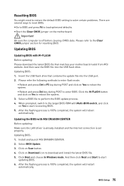
... completed, the system will restart automatically. Important Be sure the computer is set properly. Click the M-FLASH button and click on the motherboard. Updating BIOS: 1. After the flashing process is 100% completed, the system will reboot automatically. Click on Download icon to reboot the... BIOS update process. 4. Please refer to start recovering BIOS. 5. Insert the USB flash drive that matches your motherboard model from MSI website. Install and launch MSI DRAGON CENTER. 2. Select BIOS Update. 3. And then click Next and Start to the Clear CMOS jumper section ...
... completed, the system will restart automatically. Important Be sure the computer is set properly. Click the M-FLASH button and click on the motherboard. Updating BIOS: 1. After the flashing process is 100% completed, the system will reboot automatically. Click on Download icon to reboot the... BIOS update process. 4. Please refer to start recovering BIOS. 5. Insert the USB flash drive that matches your motherboard model from MSI website. Install and launch MSI DRAGON CENTER. 2. Select BIOS Update. 3. And then click Next and Start to the Clear CMOS jumper section ...

User Manual
Page 76
Plug the USB flash drive that matches your motherboard model from MSI® website and rename the BIOS file to flash BIOS, and the LED on rear ... flashing BIOS process is 100% completed, the LED would be off simultaneously. 76 BIOS Setup And then, save the MSI.ROM file to CPU_PWR1 and ATX_PWR1. (No other components are necessary but power supply.) 2. Important Only the FAT32 format...flash drive supports updating BIOS by Flash BIOS. 1. Press the Flash BIOS Button to MSI.ROM. Updating BIOS with Flash BIOS Button Before updating: Please download the latest BIOS file that contains the...
Plug the USB flash drive that matches your motherboard model from MSI® website and rename the BIOS file to flash BIOS, and the LED on rear ... flashing BIOS process is 100% completed, the LED would be off simultaneously. 76 BIOS Setup And then, save the MSI.ROM file to CPU_PWR1 and ATX_PWR1. (No other components are necessary but power supply.) 2. Important Only the FAT32 format...flash drive supports updating BIOS by Flash BIOS. 1. Press the Flash BIOS Button to MSI.ROM. Updating BIOS with Flash BIOS Button Before updating: Please download the latest BIOS file that contains the...


