User Manual
Page 1
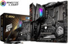
... Power Supply Unit Graphics Card Thermal Paste SATA Hard Disk Drive SATA DVD Drive Phillips Screwdriver A Package of the installations also provide video demonstrations. Quick Start Thank you for purchasing the MSI® MEG Z390 ACE motherboard. You may have even link to watch it with the web browser on your computer. This Quick Start...
... Power Supply Unit Graphics Card Thermal Paste SATA Hard Disk Drive SATA DVD Drive Phillips Screwdriver A Package of the installations also provide video demonstrations. Quick Start Thank you for purchasing the MSI® MEG Z390 ACE motherboard. You may have even link to watch it with the web browser on your computer. This Quick Start...

User Manual
Page 2
Installing a Processor https://youtu.be/4ce91YC3Oww 2 1 3 7 4 5 9 6 8 2 Quick Start
Installing a Processor https://youtu.be/4ce91YC3Oww 2 1 3 7 4 5 9 6 8 2 Quick Start

User Manual
Page 3
Installing DDR4 memory http://youtu.be/T03aDrJPyQs 1 2 3 1 2 3 DIMMA2 DIMMB2 DIMMA2 DIMMB2 DIMMB1 DIMMA2 DIMMA1 Quick Start 3
Installing DDR4 memory http://youtu.be/T03aDrJPyQs 1 2 3 1 2 3 DIMMA2 DIMMB2 DIMMA2 DIMMB2 DIMMB1 DIMMA2 DIMMA1 Quick Start 3
User Manual
Page 5
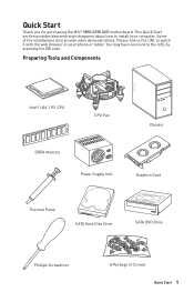
Installing the Motherboard 1 2 Quick Start 5 BAT1
Installing the Motherboard 1 2 Quick Start 5 BAT1

User Manual
Page 6
Installing SATA Drives http://youtu.be/RZsMpqxythc 2 1 3 5 4 6 Quick Start
Installing SATA Drives http://youtu.be/RZsMpqxythc 2 1 3 5 4 6 Quick Start

User Manual
Page 7
Installing a Graphics Card http://youtu.be/mG0GZpr9w_A 1 3 2 5 4 6 Quick Start 7
Installing a Graphics Card http://youtu.be/mG0GZpr9w_A 1 3 2 5 4 6 Quick Start 7
User Manual
Page 11
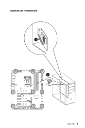
Contents Quick Start ...1 Preparing Tools and Components 1 Installing a Processor 2 Installing DDR4 memory 3 Connecting the Front Panel Header 4 Installing the Motherboard 5 Installing SATA Drives 6 Installing a Graphics Card 7 Connecting Peripheral Devices 8 Connecting the Power Connectors 9 Power On...10 Specifications...... Block Diagram ...21 Rear I/O Panel ...22 LAN Port LED Status Table 22 Audio Ports Configuration 22 Realtek Audio Console 23 Installing Antennas 25 Overview of Components 26 CPU Socket ...28 DIMM Slots...29 PCI_E1~6: PCIe Expansion Slots 30 M2_1~3: M.2 Slots ...
Contents Quick Start ...1 Preparing Tools and Components 1 Installing a Processor 2 Installing DDR4 memory 3 Connecting the Front Panel Header 4 Installing the Motherboard 5 Installing SATA Drives 6 Installing a Graphics Card 7 Connecting Peripheral Devices 8 Connecting the Power Connectors 9 Power On...10 Specifications...... Block Diagram ...21 Rear I/O Panel ...22 LAN Port LED Status Table 22 Audio Ports Configuration 22 Realtek Audio Console 23 Installing Antennas 25 Overview of Components 26 CPU Socket ...28 DIMM Slots...29 PCI_E1~6: PCIe Expansion Slots 30 M2_1~3: M.2 Slots ...
User Manual
Page 12
... 48 Hexadecimal Character Table 48 Boot Phases...48 Debug Code LED Table 48 ACPI States Codes 52 CPU Temperature 52 Installing OS, Drivers & Utilities 53 Installing Windows® 10 53 Installing Drivers 53 Installing Utilities 53 MYSTIC LIGHT...54 Device LED effect control screen 54 Nahimic 3 ...57 BIOS Setup ...60 Entering BIOS Setup 60...
... 48 Hexadecimal Character Table 48 Boot Phases...48 Debug Code LED Table 48 ACPI States Codes 52 CPU Temperature 52 Installing OS, Drivers & Utilities 53 Installing Windows® 10 53 Installing Drivers 53 Installing Utilities 53 MYSTIC LIGHT...54 Device LED effect control screen 54 Nahimic 3 ...57 BIOS Setup ...60 Entering BIOS Setup 60...

User Manual
Page 13
M-FLASH ...80 OC PROFILE ...81 HARDWARE MONITOR 82 RAID Configuration 83 Enabling Intel® Rapid Storage Technology 83 Creating RAID Volume 84 Removing a RAID Volume 85 Resetting Disks to Non-RAID 86 Rebuilding RAID Array 87 Installing RAID Driver 88 Installing Intel® Rapid Storage Technology Software 88 Intel® Optane™ Memory Configuration 89 System Requirements 89 Installing the Intel® Optane™ memory 89 Removing the Intel® Optane™ memory 91 Troubleshooting 92 Regulatory Notices 93 Contents 13
M-FLASH ...80 OC PROFILE ...81 HARDWARE MONITOR 82 RAID Configuration 83 Enabling Intel® Rapid Storage Technology 83 Creating RAID Volume 84 Removing a RAID Volume 85 Resetting Disks to Non-RAID 86 Rebuilding RAID Array 87 Installing RAID Driver 88 Installing Intel® Rapid Storage Technology Software 88 Intel® Optane™ Memory Configuration 89 System Requirements 89 Installing the Intel® Optane™ memory 89 Removing the Intel® Optane™ memory 91 Troubleshooting 92 Regulatory Notices 93 Contents 13

User Manual
Page 18
.... Dragon Center Features Special Features Continued from previous page y GAME OPTIMIZATION y OC Performance y Hardware Monitor y Eyerest y LAN Manager y Live Update Please refer to http://download.msi. y Audio ƒ Audio Boost HD ƒ Nahimic 3 ƒ Voice Boost y Network ƒ GAMING LAN with Killer LAN Manager ƒ Intel WiFi y Storage ƒ ...Extension (CORSAIR) ƒ Mystic Light Sync ƒ EZ DEBUG LED y Protection ƒ DDR4 Steel Armor ƒ M.2 Shield Frozr ƒ PCI-E Steel Armor ƒ Pre-installed IO shielding Continued on next page 18 Specifications
.... Dragon Center Features Special Features Continued from previous page y GAME OPTIMIZATION y OC Performance y Hardware Monitor y Eyerest y LAN Manager y Live Update Please refer to http://download.msi. y Audio ƒ Audio Boost HD ƒ Nahimic 3 ƒ Voice Boost y Network ƒ GAMING LAN with Killer LAN Manager ƒ Intel WiFi y Storage ƒ ...Extension (CORSAIR) ƒ Mystic Light Sync ƒ EZ DEBUG LED y Protection ƒ DDR4 Steel Armor ƒ M.2 Shield Frozr ƒ PCI-E Steel Armor ƒ Pre-installed IO shielding Continued on next page 18 Specifications
User Manual
Page 20
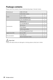
It should contain: Motherboard MEG Z390 ACE SATA 6Gb/s Cables 4 LED Y Cable 1 Cable LED JCORSAIR Cable 1 LED JRAINBOW Cable 1 Antenna Set 1 SLI HB BRIDGE M 1 M.2 Screw 3 Accessories Case Badge 1 SATA Cable Lables 1 Product Registration Card 1 Application DVD Driver DVD 1 User Manual 1 Documentation Quick Installation Guide 1 Important If any of your retailer. 20 Package contents Package contents Please check the contents of the above items are damaged or missing, please contact your motherboard package.
It should contain: Motherboard MEG Z390 ACE SATA 6Gb/s Cables 4 LED Y Cable 1 Cable LED JCORSAIR Cable 1 LED JRAINBOW Cable 1 Antenna Set 1 SLI HB BRIDGE M 1 M.2 Screw 3 Accessories Case Badge 1 SATA Cable Lables 1 Product Registration Card 1 Application DVD Driver DVD 1 User Manual 1 Documentation Quick Installation Guide 1 Important If any of your retailer. 20 Package contents Package contents Please check the contents of the above items are damaged or missing, please contact your motherboard package.

User Manual
Page 23
... dialog When you plug into a device at an audio jack, a dialogue window will provide you a complete guidance of the speakers that you which device is installed. The check sign indicates the devices as shown on the next page. controls the volume or balance the right/left side of anticipated sound effect...
... dialog When you plug into a device at an audio jack, a dialogue window will provide you a complete guidance of the speakers that you which device is installed. The check sign indicates the devices as shown on the next page. controls the volume or balance the right/left side of anticipated sound effect...

User Manual
Page 25
Rear I/O Panel 25 Combine the antenna with the base. 2. Screw two antenna cables tight to the WiFi antenna connectors as possible. Place the antenna as high as shown. 2 1 3. Installing Antennas 1.
Rear I/O Panel 25 Combine the antenna with the base. 2. Screw two antenna cables tight to the WiFi antenna connectors as possible. Place the antenna as high as shown. 2 1 3. Installing Antennas 1.
User Manual
Page 28
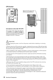
... attempting to prevent overheating and maintain system stability. y Whenever the CPU is the Pin 1 indicator. The golden triangle is not installed, always protect the CPU socket pins by inadequate operation beyond product specifications is necessary to overclock, please make sure the cooling fans work...properly to protect the CPU from the power outlet before booting your system. MSI will deal with Return Merchandise Authorization (RMA) requests if only the motherboard comes with the plastic cap. MSI® does not guarantee the damages or risks caused by covering the ...
... attempting to prevent overheating and maintain system stability. y Whenever the CPU is the Pin 1 indicator. The golden triangle is not installed, always protect the CPU socket pins by inadequate operation beyond product specifications is necessary to overclock, please make sure the cooling fans work...properly to protect the CPU from the power outlet before booting your system. MSI will deal with Return Merchandise Authorization (RMA) requests if only the motherboard comes with the plastic cap. MSI® does not guarantee the damages or risks caused by covering the ...
User Manual
Page 29
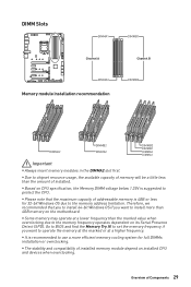
... devices when overclocking. y It is recommended to operate the memory at the marked or at a lower frequency than the amount of installed. to set the memory frequency if you want to use a more than 4GB memory on its Serial Presence Detect (SPD). y The...be a little less than the marked value when overclocking due to protect the CPU. DIMM Slots DIMMA1 DIMMB1 Channel A Channel B DIMMA2 Memory module installation recommendation DIMMB2 DIMMA2 DIMMB2 DIMMA2 DIMMB2 DIMMB1 DIMMA2 DIMMA1 Important y Always insert memory modules in the DIMMA2 slot first. y Some memory may operate ...
... devices when overclocking. y It is recommended to operate the memory at the marked or at a lower frequency than the amount of installed. to set the memory frequency if you want to use a more than 4GB memory on its Serial Presence Detect (SPD). y The...be a little less than the marked value when overclocking due to protect the CPU. DIMM Slots DIMMA1 DIMMB1 Channel A Channel B DIMMA2 Memory module installation recommendation DIMMB2 DIMMA2 DIMMB2 DIMMA2 DIMMB2 DIMMB1 DIMMA2 DIMMA1 Important y Always insert memory modules in the DIMMA2 slot first. y Some memory may operate ...
User Manual
Page 30
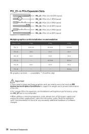
...PCIe 3.0 x1 (PCH lanes) PCI_E4: PCIe 3.0 x8 (CPU lanes) PCI_E5: PCIe 3.0 x1 (PCH lanes) PCI_E6: PCIe 3.0 x4 (CPU lanes) Multiple graphics cards installation recommendation Graphics Card Single 2-Way PCI_E1 @ 3.0 x16 @ 3.0 x8 PCI_E2 3.0 x1 3.0 x1 PCI_E3 3.0 x1 3.0 x1 PCI_E4 ─ @ 3.0 x8 PCI_E5 3.0 x1...only) 3-Way* @ 3.0 x8 3.0 x1 3.0 x1 @3.0 x4 3.0 x1 @3.0 x4 Important y If you install a large and heavy graphics card, you need to use a tool such as MSI Gaming Series Graphics Card Bolster to support its weight and to check for any necessary additional hardware or software...
...PCIe 3.0 x1 (PCH lanes) PCI_E4: PCIe 3.0 x8 (CPU lanes) PCI_E5: PCIe 3.0 x1 (PCH lanes) PCI_E6: PCIe 3.0 x4 (CPU lanes) Multiple graphics cards installation recommendation Graphics Card Single 2-Way PCI_E1 @ 3.0 x16 @ 3.0 x8 PCI_E2 3.0 x1 3.0 x1 PCI_E3 3.0 x1 3.0 x1 PCI_E4 ─ @ 3.0 x8 PCI_E5 3.0 x1...only) 3-Way* @ 3.0 x8 3.0 x1 3.0 x1 @3.0 x4 3.0 x1 @3.0 x4 Important y If you install a large and heavy graphics card, you need to use a tool such as MSI Gaming Series Graphics Card Bolster to support its weight and to check for any necessary additional hardware or software...
User Manual
Page 31
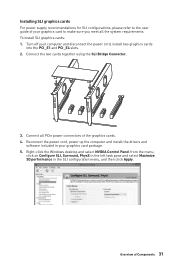
..., PhysX in the left task pane and select Maximize 3D performance in your graphics card package. 5. Connect all the system requirements. Installing SLI graphics cards For power supply recommendations for SLI configurations, please refer to make sure you meet all PCIe power connectors of your graphics...of the graphics cards. 4. Turn off your computer and disconnect the power cord, install two graphics cards into the PCI_E1 and PCI_E4 slots. 2. Reconnect the power cord, power up the computer and install the drivers and software included in the SLI configuration menu, and then click Apply...
..., PhysX in the left task pane and select Maximize 3D performance in your graphics card package. 5. Connect all the system requirements. Installing SLI graphics cards For power supply recommendations for SLI configurations, please refer to make sure you meet all PCIe power connectors of your graphics...of the graphics cards. 4. Turn off your computer and disconnect the power cord, install two graphics cards into the PCI_E1 and PCI_E4 slots. 2. Reconnect the power cord, power up the computer and install the drivers and software included in the SLI configuration menu, and then click Apply...
User Manual
Page 32
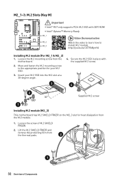
...M.2 mounting screw from the M.2 module. 1. Secure the M.2 SSD in place with UEFI ROM. Insert your M.2 SSD. 3. http://youtu.be/JCTFABytrYA Installing M.2 module (For M2_1 & M2_2) 1. Lift the M.2 SHIELD FROZR and remove the protecting film from the thermal pads. 2 1 32 Overview of ...M.2 Slots (Key M) Important y Intel® RST only supports PCIe M.2 SSD with the supplied M.2 screw. 3 4 2 30° Supplied M.2 screw 1 Installing M.2 module (M2_3) This motherboard has M.2 SHIELD FROZR on the M2_3 slot for your M.2 SSD into the M.2 slot at a 30-degree angle. 4. Move...
...M.2 mounting screw from the M.2 module. 1. Secure the M.2 SSD in place with UEFI ROM. Insert your M.2 SSD. 3. http://youtu.be/JCTFABytrYA Installing M.2 module (For M2_1 & M2_2) 1. Lift the M.2 SHIELD FROZR and remove the protecting film from the thermal pads. 2 1 32 Overview of ...M.2 Slots (Key M) Important y Intel® RST only supports PCIe M.2 SSD with the supplied M.2 screw. 3 4 2 30° Supplied M.2 screw 1 Installing M.2 module (M2_3) This motherboard has M.2 SHIELD FROZR on the M2_3 slot for your M.2 SSD into the M.2 slot at a 30-degree angle. 4. Move...
User Manual
Page 34
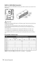
y SATA cables have identical plugs on either sides of Components y The SATA5 will be unavailable when installing M.2 PCIe device into M2_2 slot. y The SATA2 will be unavailable when installing M.2 SATA device into M2_1 slot. Data loss may result during transmission otherwise. SATA2 SATA1 SATA4 SATA3 SATA6 SATA5 Important y Please do not fold the... of the cable. Each connector can connect to the motherboard for space saving purposes. However, it is recommended that the flat connector be unavailable when installing M.2 SATA device into M2_2 slot.
y SATA cables have identical plugs on either sides of Components y The SATA5 will be unavailable when installing M.2 PCIe device into M2_2 slot. y The SATA2 will be unavailable when installing M.2 SATA device into M2_1 slot. Data loss may result during transmission otherwise. SATA2 SATA1 SATA4 SATA3 SATA6 SATA5 Important y Please do not fold the... of the cable. Each connector can connect to the motherboard for space saving purposes. However, it is recommended that the flat connector be unavailable when installing M.2 SATA device into M2_2 slot.
User Manual
Page 39
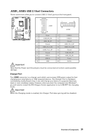
... your smartphone or USB-powered devices. Overview of Components 39 Charger Port The JUSB3 connector is enabled, the Charger Port data syncing will need to install the MSI Dragon Center application to turn ON/OFF the charging mode. JUSB1, JUSB3: USB 3.1 Gen1 Connectors These connectors allow you will be connected correctly to...
... your smartphone or USB-powered devices. Overview of Components 39 Charger Port The JUSB3 connector is enabled, the Charger Port data syncing will need to install the MSI Dragon Center application to turn ON/OFF the charging mode. JUSB1, JUSB3: USB 3.1 Gen1 Connectors These connectors allow you will be connected correctly to...


