User Manual
Page 11
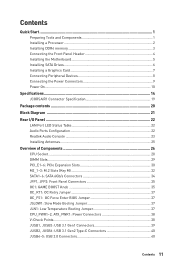
... a Processor 2 Installing DDR4 memory 3 Connecting the Front Panel Header 4 Installing the Motherboard 5 Installing SATA Drives 6 Installing a Graphics Card 7 Connecting Peripheral Devices 8 Connecting the Power Connectors 9 Power On...10 Specifications...14 JCORSAIR1 Connector Specification 19 Package contents 20 Block Diagram ...21 Rear I/O Panel ...22 LAN Port LED Status Table 22 Audio Ports Configuration 22 Realtek Audio Console 23 Installing Antennas 25 Overview of Components 26 CPU Socket ...28 DIMM Slots...29 PCI_E1~6: PCIe Expansion Slots 30 M2_1~3: M.2 Slots (Key M 32...
... a Processor 2 Installing DDR4 memory 3 Connecting the Front Panel Header 4 Installing the Motherboard 5 Installing SATA Drives 6 Installing a Graphics Card 7 Connecting Peripheral Devices 8 Connecting the Power Connectors 9 Power On...10 Specifications...14 JCORSAIR1 Connector Specification 19 Package contents 20 Block Diagram ...21 Rear I/O Panel ...22 LAN Port LED Status Table 22 Audio Ports Configuration 22 Realtek Audio Console 23 Installing Antennas 25 Overview of Components 26 CPU Socket ...28 DIMM Slots...29 PCI_E1~6: PCIe Expansion Slots 30 M2_1~3: M.2 Slots (Key M 32...
User Manual
Page 12
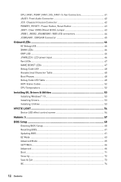
... Onboard LEDs ...46 EZ Debug LED...46 DIMM LEDs ...46 XMP LED ...46 JPWRLED1: LED power input 46 Fan LEDs...47 GAME BOOST LEDs 47 Debug Code LED 48 Hexadecimal Character Table 48 Boot Phases...48 Debug Code LED Table 48 ACPI States Codes 52 CPU Temperature 52 Installing OS, Drivers & Utilities 53 Installing Windows® 10 53 Installing Drivers 53 Installing Utilities 53 MYSTIC LIGHT...54 Device LED effect control screen 54 Nahimic 3 ...57 BIOS Setup ...60 Entering BIOS Setup 60 Resetting BIOS...61 Updating BIOS...61 EZ Mode ...63 Advanced Mode ...65 SETTINGS...
... Onboard LEDs ...46 EZ Debug LED...46 DIMM LEDs ...46 XMP LED ...46 JPWRLED1: LED power input 46 Fan LEDs...47 GAME BOOST LEDs 47 Debug Code LED 48 Hexadecimal Character Table 48 Boot Phases...48 Debug Code LED Table 48 ACPI States Codes 52 CPU Temperature 52 Installing OS, Drivers & Utilities 53 Installing Windows® 10 53 Installing Drivers 53 Installing Utilities 53 MYSTIC LIGHT...54 Device LED effect control screen 54 Nahimic 3 ...57 BIOS Setup ...60 Entering BIOS Setup 60 Resetting BIOS...61 Updating BIOS...61 EZ Mode ...63 Advanced Mode ...65 SETTINGS...
User Manual
Page 17
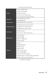
... BIOS Features Software Continued from previous page y 1x Clear CMOS jumper y 1x Slow mode jumper y 1x OC retry jumper y 1x OC force enter BIOS jumper y 1x Low Temperature Booting Jumper y 1x 2-Digit Debug Code LED y 4x EZ Debug LED NUVOTON NCT6797 Controller Chip y CPU/System temperature detection y CPU/System fan speed detection y CPU/System fan speed control y ATX Form Factor y 12 in . (30.5 cm x 24.4 cm) y 1x 128 Mb flash y UEFI AMI BIOS y ACPI 6.1, SMBIOS 2.8 y Multi-language y Drivers y DRAGON CENTER y Nahimic Audio y MYSTIC LIGHT y Killer Control Center y CPU-Z MSI...
... BIOS Features Software Continued from previous page y 1x Clear CMOS jumper y 1x Slow mode jumper y 1x OC retry jumper y 1x OC force enter BIOS jumper y 1x Low Temperature Booting Jumper y 1x 2-Digit Debug Code LED y 4x EZ Debug LED NUVOTON NCT6797 Controller Chip y CPU/System temperature detection y CPU/System fan speed detection y CPU/System fan speed control y ATX Form Factor y 12 in . (30.5 cm x 24.4 cm) y 1x 128 Mb flash y UEFI AMI BIOS y ACPI 6.1, SMBIOS 2.8 y Multi-language y Drivers y DRAGON CENTER y Nahimic Audio y MYSTIC LIGHT y Killer Control Center y CPU-Z MSI...

User Manual
Page 49
...) data reading Memory initialization. Configuring memory Memory initialization (other) Memory Installed CPU post-memory initialization is started Pre-memory PCH initialization (PCH module specific) Memory initialization. SEC Error Codes 0C - 0D 0E 0F Reserved for future AMI SEC error codes Microcode not found or micro-code update is failed Internal CPU error Reset PPI is not available Reserved for future AMI error codes Onboard LEDs 49 Programming memory timing information Memory initialization. Application Processor(s) (AP) initialization CPU post-memory initialization. SPD...
...) data reading Memory initialization. Configuring memory Memory initialization (other) Memory Installed CPU post-memory initialization is started Pre-memory PCH initialization (PCH module specific) Memory initialization. SEC Error Codes 0C - 0D 0E 0F Reserved for future AMI SEC error codes Microcode not found or micro-code update is failed Internal CPU error Reset PPI is not available Reserved for future AMI error codes Onboard LEDs 49 Programming memory timing information Memory initialization. Application Processor(s) (AP) initialization CPU post-memory initialization. SPD...
User Manual
Page 50
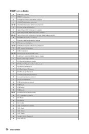
...AMI DXE codes Boot Device Selection (BDS) phase is started Driver connecting is started PCI Bus initialization is started PCI Bus Hot Plug Controller Initialization PCI Bus Enumeration 32 PCI Bus Request Resources PCI Bus Assign Resources Console Output devices connect Console input devices connect Super IO Initialization USB initialization is started USB Reset USB Detect USB Enable Reserved for future AMI codes IDE initialization is started IDE Reset IDE Detect IDE Enable SCSI initialization is started SCSI Reset SCSI Detect SCSI Enable Setup Verifying Password Start of Setup 50 Onboard LEDs
...AMI DXE codes Boot Device Selection (BDS) phase is started Driver connecting is started PCI Bus initialization is started PCI Bus Hot Plug Controller Initialization PCI Bus Enumeration 32 PCI Bus Request Resources PCI Bus Assign Resources Console Output devices connect Console input devices connect Super IO Initialization USB initialization is started USB Reset USB Detect USB Enable Reserved for future AMI codes IDE initialization is started IDE Reset IDE Detect IDE Enable SCSI initialization is started SCSI Reset SCSI Detect SCSI Enable Setup Verifying Password Start of Setup 50 Onboard LEDs

User Manual
Page 51
... Set Virtual Address MAP End B2 Legacy Option ROM Initialization B3 System Reset B4 USB hot plug B5 PCI bus hot plug B6 Clean-up of NVRAM B7 Configuration Reset (reset of the Architectural Protocols are found D8 Invalid password D9 Error loading Boot Option (LoadImage returned error) DA Boot Option is failed (StartImage returned error) DB Flash update is failed DC Reset protocol is called by the DXE IPL) S3 Boot Script execution Video repost OS S3 wake...
... Set Virtual Address MAP End B2 Legacy Option ROM Initialization B3 System Reset B4 USB hot plug B5 PCI bus hot plug B6 Clean-up of NVRAM B7 Configuration Reset (reset of the Architectural Protocols are found D8 Invalid password D9 Error loading Boot Option (LoadImage returned error) DA Boot Option is failed (StartImage returned error) DB Flash update is failed DC Reset protocol is called by the DXE IPL) S3 Boot Script execution Video repost OS S3 wake...

User Manual
Page 53
.../USB into your computer in the Drivers/Software tab. 5. The installer will prompt you can still manually execute the DVDSetup.exe from the Boot Menu. 6. Click OK button to get into Boot Menu. 5. Installing OS, Drivers & Utilities Please download and update the latest utilities and drivers at www.msi.com Installing Windows® 10 1. Press F11 key during the computer POST (Power-On Self Test) to finish. 7. Follow the instructions on the screen to restart. 7. Start...
.../USB into your computer in the Drivers/Software tab. 5. The installer will prompt you can still manually execute the DVDSetup.exe from the Boot Menu. 6. Click OK button to get into Boot Menu. 5. Installing OS, Drivers & Utilities Please download and update the latest utilities and drivers at www.msi.com Installing Windows® 10 1. Press F11 key during the computer POST (Power-On Self Test) to finish. 7. Follow the instructions on the screen to restart. 7. Start...
User Manual
Page 57
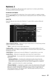
.../Off Button - it contains audio effects, microphone effects and Sound Tracker. Nahimic 3 Nahimic 3 is designed to separately control any of the 5 audio effects. ƒ Surround Sound - Installation and Update Nahimic 3 is included in the audio driver. displays the type of audio device currently being used as output, as well as you to offer the best audio experience it is an audio effect mainly dedicated to enter a night mode by removing some...
.../Off Button - it contains audio effects, microphone effects and Sound Tracker. Nahimic 3 Nahimic 3 is designed to separately control any of the 5 audio effects. ƒ Surround Sound - Installation and Update Nahimic 3 is included in the audio driver. displays the type of audio device currently being used as output, as well as you to offer the best audio experience it is an audio effect mainly dedicated to enter a night mode by removing some...
User Manual
Page 61
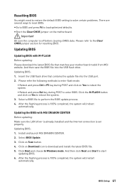
... and Start to the Clear CMOS jumper section for resetting BIOS. Select a BIOS file to load optimized defaults. Install and launch MSI DRAGON CENTER. 2. Click Next and choose In Windows mode. After the flashing process is off before clearing CMOS data. Updating BIOS Updating BIOS with MSI DRAGON CENTER Before updating: Make sure the LAN driver is already installed and the Internet connection is 100% completed, the system will restart automatically. Insert the USB flash drive that matches your motherboard model from MSI...
... and Start to the Clear CMOS jumper section for resetting BIOS. Select a BIOS file to load optimized defaults. Install and launch MSI DRAGON CENTER. 2. Click Next and choose In Windows mode. After the flashing process is off before clearing CMOS data. Updating BIOS Updating BIOS with MSI DRAGON CENTER Before updating: Make sure the LAN driver is already installed and the Internet connection is 100% completed, the system will restart automatically. Insert the USB flash drive that matches your motherboard model from MSI...
User Manual
Page 63
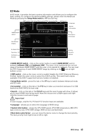
... the mouse to enable/ disable the X.M.P. (Extreme Memory Profile). y System information - XMP switch Setup Mode switch Screenshot Search Language System information GAME BOOST switch Boot device priority bar Information display M-Flash Favorites Hardware Monitor Function buttons y GAME BOOST switch - shows the CPU/ DDR speed, CPU/ MB temperature, MB/ CPU type, memory size, CPU/ DDR voltage, BIOS version and build date. you can read the CPU frequency of each GAME BOOST stage by pressing the Setup Mode switch or F7 function key. You can...
... the mouse to enable/ disable the X.M.P. (Extreme Memory Profile). y System information - XMP switch Setup Mode switch Screenshot Search Language System information GAME BOOST switch Boot device priority bar Information display M-Flash Favorites Hardware Monitor Function buttons y GAME BOOST switch - shows the CPU/ DDR speed, CPU/ MB temperature, MB/ CPU type, memory size, CPU/ DDR voltage, BIOS version and build date. you can read the CPU frequency of each GAME BOOST stage by pressing the Setup Mode switch or F7 function key. You can...
User Manual
Page 64
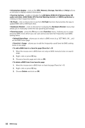
... to add the frequently-used BIOS setting items. ƒ Default HomePage - allows you to a favorite page (Favorite 1~5) 1. Choose Delete and click on OK. ƒ To delete a BIOS item from favorite page 1. enable or disable the LAN Option ROM, M.2/ Optane Genie, HD audio controller, AHCI/ RAID, CPU Fan Fail Warning Control and BIOS Log Review by percentage. y Hardware Monitor - allows you to enter Favorites menu. Right-click or press F2 key. 3. Right-click or...
... to add the frequently-used BIOS setting items. ƒ Default HomePage - allows you to a favorite page (Favorite 1~5) 1. Choose Delete and click on OK. ƒ To delete a BIOS item from favorite page 1. enable or disable the LAN Option ROM, M.2/ Optane Genie, HD audio controller, AHCI/ RAID, CPU Fan Fail Warning Control and BIOS Log Review by percentage. y Hardware Monitor - allows you to enter Favorites menu. Right-click or press F2 key. 3. Right-click or...

User Manual
Page 67
...] The power LED blinks to enter the sub-menu. BIOS Setup 67 Press Enter to utilize more than 4x GPUs. [Disabled] Disables this function. fOnboard LAN Controller [Enabled] Enables or disables the onboard LAN controller. It is only available if the system supports 64-bit PCI decoding. [Enabled] Allows you to enter the submenu. fCPU Over Temperature Alert [Auto] Enables or disables the CPU overheating alert when CPU temperature is enabled. [Enabled] Enables the onboard LAN Boot ROM. [Disabled] Disables the onboard LAN Boot ROM. fPEG X - fNetwork Stack [Disabled] Sets UEFI network stack...
...] The power LED blinks to enter the sub-menu. BIOS Setup 67 Press Enter to utilize more than 4x GPUs. [Disabled] Disables this function. fOnboard LAN Controller [Enabled] Enables or disables the onboard LAN controller. It is only available if the system supports 64-bit PCI decoding. [Enabled] Allows you to enter the submenu. fCPU Over Temperature Alert [Auto] Enables or disables the CPU overheating alert when CPU temperature is enabled. [Enabled] Enables the onboard LAN Boot ROM. [Disabled] Disables the onboard LAN Boot ROM. fPEG X - fNetwork Stack [Disabled] Sets UEFI network stack...

User Manual
Page 68
... onboard High Definition Audio controller. f USB Configuration Sets the onboard USB controller and device function. fXHCI Hand-off [Diasbled] Enables or disables XHCI hand-off support for the SATA ports. fUSB Controller [Enabled] Enables or disables all USB controller. This item will support Ipv4 protocol. This item will support Ipv6 protocol. fSATAx Hot Plug [Disabled] Allows user to enter the submenu. fIpv4 PXE Support [Enabled] When Enabled, the system UEFI network stack will appear when Network Stack is installed and support RAID...
... onboard High Definition Audio controller. f USB Configuration Sets the onboard USB controller and device function. fXHCI Hand-off [Diasbled] Enables or disables XHCI hand-off support for the SATA ports. fUSB Controller [Enabled] Enables or disables all USB controller. This item will support Ipv4 protocol. This item will support Ipv6 protocol. fSATAx Hot Plug [Disabled] Allows user to enter the submenu. fIpv4 PXE Support [Enabled] When Enabled, the system UEFI network stack will appear when Network Stack is installed and support RAID...

User Manual
Page 69
... Resume By USB Device is connected and enable the legacy USB support. [Enabled] Enable the USB support under legacy mode. f Windows OS Configuration Sets Windows OS detailed configuration and behaviors. Press Enter to enter the submenu. fWindows 10 WHQL Support [Disabled] Enables the supports for Windows 10 or disables for all installed devices & utilities (hardware & software) should meet the Windows 10 requirements. [Enabled] The system will switch to UEFI mode to meet the Windows equirement. [Disabled] Disables this function. BIOS Setup 69 fUSB Standby Power at...
... Resume By USB Device is connected and enable the legacy USB support. [Enabled] Enable the USB support under legacy mode. f Windows OS Configuration Sets Windows OS detailed configuration and behaviors. Press Enter to enter the submenu. fWindows 10 WHQL Support [Disabled] Enables the supports for Windows 10 or disables for all installed devices & utilities (hardware & software) should meet the Windows 10 requirements. [Enabled] The system will switch to UEFI mode to meet the Windows equirement. [Disabled] Disables this function. BIOS Setup 69 fUSB Standby Power at...

User Manual
Page 71
... (using the + and - fResume By PCI-E Device [Disabled] Enables or disables the wake up function of installed PCI-E expansion cards, integrated LAN controllers or USB devices which are supported by third party integrated chips. [Enabled] Enables the system to be awakened from the power saving modes when activity or input signal of SSD will automatically resume (boot up by long pressing the power button about 4 seconds when the system is detected. [Disabled] Disables this function. Boot Sets the...
... (using the + and - fResume By PCI-E Device [Disabled] Enables or disables the wake up function of installed PCI-E expansion cards, integrated LAN controllers or USB devices which are supported by third party integrated chips. [Enabled] Enables the system to be awakened from the power saving modes when activity or input signal of SSD will automatically resume (boot up by long pressing the power button about 4 seconds when the system is detected. [Disabled] Disables this function. Boot Sets the...

User Manual
Page 77
... message during boot when the CPU or memory has been replaced. [Enabled] [Disabled] The system will set it manually. This sub-menu displays the information of installed memory. fHyper-Threading [Enabled] Intel Hyper-Threading technology treats the multi cores inside the processor as multi logical processors that do not support the processor with older operating system that can execute instructions simultaneously. BIOS Setup 77 Disables this way, the system performance is highly improved. Read...
... message during boot when the CPU or memory has been replaced. [Enabled] [Disabled] The system will set it manually. This sub-menu displays the information of installed memory. fHyper-Threading [Enabled] Intel Hyper-Threading technology treats the multi cores inside the processor as multi logical processors that do not support the processor with older operating system that can execute instructions simultaneously. BIOS Setup 77 Disables this way, the system performance is highly improved. Read...

User Manual
Page 78
... data and instructions into L2 cache from overheating. [Enabled] Throttles down the CPU core clock speed when the CPU is a processor power management technology defined by ACPI. [Auto] This setting will be configured automatically by BIOS. [Enabled] Detects the idle state of C-state depend on the installed CPU. This item appears when Intel C-State is idle. The system can function as multiple systems virtually. [Disabled] Disables this function. fC1E Support [Disabled] Enables or disables the...
... data and instructions into L2 cache from overheating. [Enabled] Throttles down the CPU core clock speed when the CPU is a processor power management technology defined by ACPI. [Auto] This setting will be configured automatically by BIOS. [Enabled] Detects the idle state of C-state depend on the installed CPU. This item appears when Intel C-State is idle. The system can function as multiple systems virtually. [Disabled] Disables this function. fC1E Support [Disabled] Enables or disables the...
User Manual
Page 88
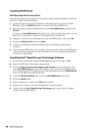
... the Windows Control Panel, you to restart, click OK button to open the Intel® Rapid Storage Technology software. 88 RAID Configuration Navigate to choose what happens with Intel RAID Drivers and then click Browse. ƒ To make an Intel RAID Drivers USB flash drive. Double-click the Intel® Rapid Storage Technology icon to install a third party RAID driver. 2. Insert the MSI Driver Disc into the optical drive. 3. If you turn...
... the Windows Control Panel, you to restart, click OK button to open the Intel® Rapid Storage Technology software. 88 RAID Configuration Navigate to choose what happens with Intel RAID Drivers and then click Browse. ƒ To make an Intel RAID Drivers USB flash drive. Double-click the Intel® Rapid Storage Technology icon to install a third party RAID driver. 2. Insert the MSI Driver Disc into the optical drive. 3. If you turn...
User Manual
Page 89
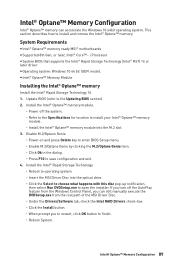
... the Specifications for location to open the installer. System Requirements y Intel® Optane™ memory ready MSI® motherboards y Supported 8th Gen, or later, Intel® Core™ - Intel® Optane™ Memory Configuration 89 Update BIOS (refer to finish. ˜ Reboot System. i Processor y System BIOS that supports the Intel® Rapid Storage Technology (Intel® RST) 16 or later driver y Operating system: Windows 10 64 bit (UEFI mode).
... the Specifications for location to open the installer. System Requirements y Intel® Optane™ memory ready MSI® motherboards y Supported 8th Gen, or later, Intel® Core™ - Intel® Optane™ Memory Configuration 89 Update BIOS (refer to finish. ˜ Reboot System. i Processor y System BIOS that supports the Intel® Rapid Storage Technology (Intel® RST) 16 or later driver y Operating system: Windows 10 64 bit (UEFI mode).
User Manual
Page 92
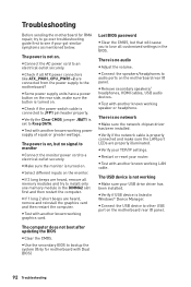
... IO panel. y Remove secondary speakers/ headphones, HDMI cables, USB audio devices. y Connect the USB device to audio ports on the motherboard rear IO panel. The power is connected to Keep DATA. y Check if the power switch cable is not on. There is set to JFP1 pin header properly. y Test with another known working speaker or headphone. y Verify the Clear CMOS jumper JBAT1 is no audio y Adjust the volume. Troubleshooting Before sending the motherboard for motherboard with Dual BIOS) 92 Troubleshooting The power is listed in Windows® Device Manager...
... IO panel. y Remove secondary speakers/ headphones, HDMI cables, USB audio devices. y Connect the USB device to audio ports on the motherboard rear IO panel. The power is connected to Keep DATA. y Check if the power switch cable is not on. There is set to JFP1 pin header properly. y Test with another known working speaker or headphone. y Verify the Clear CMOS jumper JBAT1 is no audio y Adjust the volume. Troubleshooting Before sending the motherboard for motherboard with Dual BIOS) 92 Troubleshooting The power is listed in Windows® Device Manager...


