
User Manual
Page 13
... a Processor 3 Installing DDR4 memory 5 Connecting the Front Panel Header 6 Installing the Motherboard 7 Connecting the Power Connectors 8 Installing SATA Drives 9 Installing a Graphics Card 10 Connecting Peripheral Devices 11 Power On...12 Specifications...16 JCORSAIR1 Connector Specification 23 Package contents 23 Block Diagram ...24 Rear I/O Panel ...25 LAN Port LED Status Table 25 Audio Ports Configuration 25 Realtek Audio Console 26 Installing Antennas 28 Overview of Components 29 Processor Socket 31 DIMM Slots...32 PCI_E1~5: PCIe Expansion Slots 33 M2_1~3: M.2 Slots (Key...
... a Processor 3 Installing DDR4 memory 5 Connecting the Front Panel Header 6 Installing the Motherboard 7 Connecting the Power Connectors 8 Installing SATA Drives 9 Installing a Graphics Card 10 Connecting Peripheral Devices 11 Power On...12 Specifications...16 JCORSAIR1 Connector Specification 23 Package contents 23 Block Diagram ...24 Rear I/O Panel ...25 LAN Port LED Status Table 25 Audio Ports Configuration 25 Realtek Audio Console 26 Installing Antennas 28 Overview of Components 29 Processor Socket 31 DIMM Slots...32 PCI_E1~5: PCIe Expansion Slots 33 M2_1~3: M.2 Slots (Key...
User Manual
Page 14
... BIOS) Jumper 44 POWER1, RESET1: Power Button, Reset Button 44 JRGB1: RGB LED connector 45 JRAINBOW1~2: Addressable RGB LED connectors 46 JCORSAIR1: CORSAIR Connector 47 Onboard LEDs ...48 EZ Debug LED...48 JPWRLED1: LED power input 48 Debug Code LED 48 Hexadecimal Character Table 49 Boot Phases...49 Debug Code LED Table 49 ACPI States Codes 53 Installing OS, Drivers & Utilities 54 Installing Windows® 10 54 Installing Drivers 54 Installing Utilities 54 BIOS Setup ...55 Entering BIOS Setup 55 Resetting BIOS...56 Updating BIOS...56 EZ Mode ...58 Advanced Mode ...60 SETTINGS...
... BIOS) Jumper 44 POWER1, RESET1: Power Button, Reset Button 44 JRGB1: RGB LED connector 45 JRAINBOW1~2: Addressable RGB LED connectors 46 JCORSAIR1: CORSAIR Connector 47 Onboard LEDs ...48 EZ Debug LED...48 JPWRLED1: LED power input 48 Debug Code LED 48 Hexadecimal Character Table 49 Boot Phases...49 Debug Code LED Table 49 ACPI States Codes 53 Installing OS, Drivers & Utilities 54 Installing Windows® 10 54 Installing Drivers 54 Installing Utilities 54 BIOS Setup ...55 Entering BIOS Setup 55 Resetting BIOS...56 Updating BIOS...56 EZ Mode ...58 Advanced Mode ...60 SETTINGS...
User Manual
Page 16
Specifications CPU Chipset Memory Expansion Slots Multi-GPU Supports 2nd and 3rd Gen AMD Ryzen™ / Ryzen™ with Radeon™ Vega Graphics and 2nd Gen AMD Ryzen™ with Radeon™ Graphics Desktop Processors for Socket AM4 AMD® X570 Chipset y 4x DDR4 memory slots, support up to 128GB* ƒ 3rd Gen AMD Ryzen™ Processors support DDR4 1866/ 2133/ 2400/ 2667/ 2800/ 2933/ 3000/ 3066/ 3200 Mhz by JEDEC, and 2667...
Specifications CPU Chipset Memory Expansion Slots Multi-GPU Supports 2nd and 3rd Gen AMD Ryzen™ / Ryzen™ with Radeon™ Vega Graphics and 2nd Gen AMD Ryzen™ with Radeon™ Graphics Desktop Processors for Socket AM4 AMD® X570 Chipset y 4x DDR4 memory slots, support up to 128GB* ƒ 3rd Gen AMD Ryzen™ Processors support DDR4 1866/ 2133/ 2400/ 2667/ 2800/ 2933/ 3000/ 3066/ 3200 Mhz by JEDEC, and 2667...

User Manual
Page 30
...~5 POWER1, RESET1 Processor Socket SATA1~4 Port Type Page Fan Connectors 42 Power Connectors 39 DIMM Slots 32 Front Audio Connector 39 Clear CMOS (Reset BIOS) Jumper 44 Chassis Intrusion Connector 43 CORSAIR Connector 47 Front Panel Connectors 38 LED power input 48 Addressable RGB LED connectors 46 RGB LED connector 45 TPM Module Connector 41 USB 3.2 Gen 2 Type-C Connector 40 USB 3.2 Gen1 Connector 40 USB 2.0 Connectors 41 M.2 Slots (Key M) 36 PCIe Expansion Slots 33 Power Button, Reset Button 44 AM4 socket 31 SATA 6Gb/s Connectors 38 30 Overview...
...~5 POWER1, RESET1 Processor Socket SATA1~4 Port Type Page Fan Connectors 42 Power Connectors 39 DIMM Slots 32 Front Audio Connector 39 Clear CMOS (Reset BIOS) Jumper 44 Chassis Intrusion Connector 43 CORSAIR Connector 47 Front Panel Connectors 38 LED power input 48 Addressable RGB LED connectors 46 RGB LED connector 45 TPM Module Connector 41 USB 3.2 Gen 2 Type-C Connector 40 USB 3.2 Gen1 Connector 40 USB 2.0 Connectors 41 M.2 Slots (Key M) 36 PCIe Expansion Slots 33 Power Button, Reset Button 44 AM4 socket 31 SATA 6Gb/s Connectors 38 30 Overview...
User Manual
Page 33
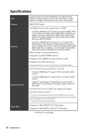
... or software changes. For 3rd Gen AMD Ryzen™ Slot Single 2-Way PCI_E1 (CPU) @4.0 x16 @4.0 x8 PCI_E2 (PCH) 4.0 x1 - yyThe PCIe x1 slots can not be unavailable when installing the PCIe card in PCI_E4 slot. yyWhen adding or removing expansion cards, always turn off the power supply and unplug the power supply power cable from the power outlet. Read the expansion card's documentation to install the PCIe devices. PCI_E2 will be used simultaneously. PCI_E1~5: PCIe Expansion Slots Slots PCI_E1...
... or software changes. For 3rd Gen AMD Ryzen™ Slot Single 2-Way PCI_E1 (CPU) @4.0 x16 @4.0 x8 PCI_E2 (PCH) 4.0 x1 - yyThe PCIe x1 slots can not be unavailable when installing the PCIe card in PCI_E4 slot. yyWhen adding or removing expansion cards, always turn off the power supply and unplug the power supply power cable from the power outlet. Read the expansion card's documentation to install the PCIe devices. PCI_E2 will be used simultaneously. PCI_E1~5: PCIe Expansion Slots Slots PCI_E1...
User Manual
Page 46
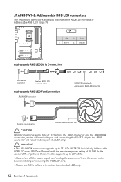
... use MSI's software to control the extended LED strip. 46 Overview of 20% brightness, the connector supports up to 75 LEDs WS2812B Individually Addressable RGB LED strips (5V/Data/Ground) with the maximum power rating of LED strips. yyAlways turn off the power supply and unplug the power cord from the power outlet before installing or removing the RGB LED strip. The JRGB connector and the JRAINBOW connector provide different voltages, and connecting...
... use MSI's software to control the extended LED strip. 46 Overview of 20% brightness, the connector supports up to 75 LEDs WS2812B Individually Addressable RGB LED strips (5V/Data/Ground) with the maximum power rating of LED strips. yyAlways turn off the power supply and unplug the power cord from the power outlet before installing or removing the RGB LED strip. The JRGB connector and the JRAINBOW connector provide different voltages, and connecting...

User Manual
Page 50
... Memory initialization. Boot Strap Processor (BSP) selection 36 CPU post-memory initialization. System Management Mode (SMM) initialization 37 Post-Memory System Agent initialization is started 38 - 3A Post-Memory System Agent initialization (System Agent module specific) 3B Post-Memory PCH initialization is started 3C - 3E Post-Memory PCH initialization (PCH module specific) 4F DXE IPL is started PEI Error Codes 4B Memory not installed (For Summit CPU) E0 Memory not installed (For Bristol CPU) DXE Progress Codes 60 DXE Core...
... Memory initialization. Boot Strap Processor (BSP) selection 36 CPU post-memory initialization. System Management Mode (SMM) initialization 37 Post-Memory System Agent initialization is started 38 - 3A Post-Memory System Agent initialization (System Agent module specific) 3B Post-Memory PCH initialization is started 3C - 3E Post-Memory PCH initialization (PCH module specific) 4F DXE IPL is started PEI Error Codes 4B Memory not installed (For Summit CPU) E0 Memory not installed (For Bristol CPU) DXE Progress Codes 60 DXE Core...
User Manual
Page 51
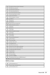
... IDE initialization is started A1 IDE Reset A2 IDE Detect A3 IDE Enable A4 SCSI initialization is started A5 SCSI Reset A6 SCSI Detect A7 SCSI Enable A8 Setup Verifying Password A9 Start of Setup AB Setup Input Wait AD Ready To Boot event AE Legacy Boot event AF Exit Boot Services event B0 Runtime Set Virtual Address MAP Begin B1 Runtime Set Virtual Address MAP End B2 Legacy Option ROM Initialization B3 System Reset B4 USB hot plug B5 PCI bus...
... IDE initialization is started A1 IDE Reset A2 IDE Detect A3 IDE Enable A4 SCSI initialization is started A5 SCSI Reset A6 SCSI Detect A7 SCSI Enable A8 Setup Verifying Password A9 Start of Setup AB Setup Input Wait AD Ready To Boot event AE Legacy Boot event AF Exit Boot Services event B0 Runtime Set Virtual Address MAP Begin B1 Runtime Set Virtual Address MAP End B2 Legacy Option ROM Initialization B3 System Reset B4 USB hot plug B5 PCI bus...

User Manual
Page 54
... the DVDSetup.exe from the Windows Control Panel, you to restart. 7. Select the Windows® 10 installation disc/USB from CD or DVD... Insert MSI® Driver Disc into Boot Menu. 5. Open the installer as described above. 2. Select the utilities you must complete drivers installation. 1. Click OK button to open the installer. Press F11 key during the computer POST (Power-On Self Test) to restart. 6. Installing Drivers 1. The utilities installation will then be in...
... the DVDSetup.exe from the Windows Control Panel, you to restart. 7. Select the Windows® 10 installation disc/USB from CD or DVD... Insert MSI® Driver Disc into Boot Menu. 5. Open the installer as described above. 2. Select the utilities you must complete drivers installation. 1. Click OK button to open the installer. Press F11 key during the computer POST (Power-On Self Test) to restart. 6. Installing Drivers 1. The utilities installation will then be in...
User Manual
Page 56
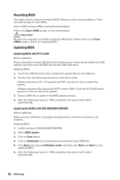
... BIOS with M-FLASH Before updating: Please download the latest BIOS file that contains the update file into the USB flash drive. Select BIOS Update. 3. Click on the motherboard. After the flashing process is set properly. And then save the BIOS file into the USB port. 2. Select a BIOS file to the Clear CMOS jumper section for resetting BIOS. Click on Download icon to reboot the system. 3. Click Next and choose In Windows mode. Install and launch MSI DRAGON CENTER. 2. yyShort the Clear CMOS jumper on Scan button...
... BIOS with M-FLASH Before updating: Please download the latest BIOS file that contains the update file into the USB flash drive. Select BIOS Update. 3. Click on the motherboard. After the flashing process is set properly. And then save the BIOS file into the USB port. 2. Select a BIOS file to the Clear CMOS jumper section for resetting BIOS. Click on Download icon to reboot the system. 3. Click Next and choose In Windows mode. Install and launch MSI DRAGON CENTER. 2. yyShort the Clear CMOS jumper on Scan button...

User Manual
Page 58
... the installed processor and memory modules support A-XMP function. yyScreenshot - yySystem information - yyInformation display - A-XMP switch Setup Mode switch Screenshot Search Language System information GAME BOOST switch Boot device priority bar Information display M-Flash Favorites Hardware Monitor Function buttons yyGAME BOOST switch - click on this tab or the F7 key to switch between Advanced mode and EZ mode. It allows you to configure the basic setting. yyLanguage - click on the inner circle to enable/ disable...
... the installed processor and memory modules support A-XMP function. yyScreenshot - yySystem information - yyInformation display - A-XMP switch Setup Mode switch Screenshot Search Language System information GAME BOOST switch Boot device priority bar Information display M-Flash Favorites Hardware Monitor Function buttons yyGAME BOOST switch - click on this tab or the F7 key to switch between Advanced mode and EZ mode. It allows you to configure the basic setting. yyLanguage - click on the inner circle to enable/ disable...

User Manual
Page 59
... to manually control the fan speed by clicking on this button to display the Hardware Monitor menu that provides the way to update BIOS with a USB flash drive. Right-click or press F2 key. 3. Move the mouse over a BIOS item not only on BIOS menu but also on OK. yyFavorites - enable or disable the LAN Option ROM, ErP Ready, AHCI/ RAID, Indication LED Control, BIOS UEFI/CSM Mode and RGB Light Control by percentage. It allows you to create personal BIOS menu where...
... to manually control the fan speed by clicking on this button to display the Hardware Monitor menu that provides the way to update BIOS with a USB flash drive. Right-click or press F2 key. 3. Move the mouse over a BIOS item not only on BIOS menu but also on OK. yyFavorites - enable or disable the LAN Option ROM, ErP Ready, AHCI/ RAID, Indication LED Control, BIOS UEFI/CSM Mode and RGB Light Control by percentage. It allows you to create personal BIOS menu where...

User Manual
Page 62
...of onboard power LED behaviors. ffIpv4 PXE Support [Enabled] When Enabled, the system UEFI network stack will vary with the installed processor. This item will appear when Network Stack is enabled. [Enabled] Enables the onboard LAN Boot ROM. [Disabled] Disables the onboard LAN Boot ROM. This item will appear when Onboard LAN Controller is Enabled. [Enabled] Enables the Ipv4 PXE boot support. [Disabled] Disables the Ipv4 PXE boot support. 62 BIOS Setup ffLAN Option ROM [Disabled] Enables or disables the legacy network Boot Option ROM for detailed settings. Press Enter to...
...of onboard power LED behaviors. ffIpv4 PXE Support [Enabled] When Enabled, the system UEFI network stack will vary with the installed processor. This item will appear when Network Stack is enabled. [Enabled] Enables the onboard LAN Boot ROM. [Disabled] Disables the onboard LAN Boot ROM. This item will appear when Onboard LAN Controller is Enabled. [Enabled] Enables the Ipv4 PXE boot support. [Disabled] Disables the Ipv4 PXE boot support. 62 BIOS Setup ffLAN Option ROM [Disabled] Enables or disables the legacy network Boot Option ROM for detailed settings. Press Enter to...

User Manual
Page 63
... hot-plugging. [RAID Mode] Enables RAID function for SATA storage devices. BIOS Setup 63 AHCI (Advanced Host Controller Interface) offers some advanced features to enter the sub-menu. ffSATAx Hot Plug [Disabled] Allows user to enable or disable the SATA hot plug support. [Enabled] Enables hot plug support for the SATA ports. [Disabled] Disables hot plug support for the operating system without XHCI hand-off feature. ffXHCI Hand-off [Enabled] Enables or disables XHCI hand-off support for the SATA ports. ffSATA Mode [AHCI Mode] Sets the operation mode of ErP and AC Power...
... hot-plugging. [RAID Mode] Enables RAID function for SATA storage devices. BIOS Setup 63 AHCI (Advanced Host Controller Interface) offers some advanced features to enter the sub-menu. ffSATAx Hot Plug [Disabled] Allows user to enable or disable the SATA hot plug support. [Enabled] Enables hot plug support for the SATA ports. [Disabled] Disables hot plug support for the operating system without XHCI hand-off feature. ffXHCI Hand-off [Enabled] Enables or disables XHCI hand-off support for the SATA ports. ffSATA Mode [AHCI Mode] Sets the operation mode of ErP and AC Power...

User Manual
Page 64
.... [Disabled] Disables this function. ffDate (of these fields (using the + and - ffWindows OS Configuration Sets Windows detailed configuration and behaviors. Press Enter to select the date & time settings). 64 BIOS Setup ffResume By RTC Alarm [Disabled] Disables or enables the system wake up by RTC Alarm. [Enabled] Enables the system to boot up on devices and UEFI mode OS. keys to enter the submenu. Press Enter to enter the sub-menu. ffRestore after AC Power Loss [Power Off] Sets...
.... [Disabled] Disables this function. ffDate (of these fields (using the + and - ffWindows OS Configuration Sets Windows detailed configuration and behaviors. Press Enter to select the date & time settings). 64 BIOS Setup ffResume By RTC Alarm [Disabled] Disables or enables the system wake up by RTC Alarm. [Enabled] Enables the system to boot up on devices and UEFI mode OS. keys to enter the submenu. Press Enter to enter the sub-menu. ffRestore after AC Power Loss [Power Off] Sets...

User Manual
Page 65
... POST messages. ffResume From S3/S4/S5 by PS/2 Mouse [Disabled] Enables or disables the system wake up by PS/2 mouse. [Enabled] Enables the system to be awakened from the power saving modes when activity or input signal of PCIe device is detected. [Disabled] Disables this function. ffResume By PCI-E Device [Disabled] Enables or disables the wake up function of installed PCI-E expansion cards, integrated LAN controllers or USB devices which are supported by third party integrated chips. [Enabled] Enables...
... POST messages. ffResume From S3/S4/S5 by PS/2 Mouse [Disabled] Enables or disables the system wake up by PS/2 mouse. [Enabled] Enables the system to be awakened from the power saving modes when activity or input signal of PCIe device is detected. [Disabled] Disables this function. ffResume By PCI-E Device [Disabled] Enables or disables the wake up function of installed PCI-E expansion cards, integrated LAN controllers or USB devices which are supported by third party integrated chips. [Enabled] Enables...
User Manual
Page 71
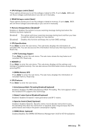
... decode instruction to enter the sub-menu. If set to Auto, BIOS will issue a warning message during boot when the memory has been replaced. [Enabled] [Disabled] The system will set these voltages automatically or you have to load the default settings for I /O Memory Management Unit) for new devices. ffCPU Technology Support Press Enter to enter the sub-menu. Disables this technology. ffIOMMU Mode (optional) Enables/disables the IOMMU (I /O Virtualization. ffCPU Voltages control [Auto] These options allows you to set the voltages related to memory. ffCPU...
... decode instruction to enter the sub-menu. If set to Auto, BIOS will issue a warning message during boot when the memory has been replaced. [Enabled] [Disabled] The system will set these voltages automatically or you have to load the default settings for I /O Memory Management Unit) for new devices. ffCPU Technology Support Press Enter to enter the sub-menu. Disables this technology. ffIOMMU Mode (optional) Enables/disables the IOMMU (I /O Virtualization. ffCPU Voltages control [Auto] These options allows you to set the voltages related to memory. ffCPU...
User Manual
Page 77
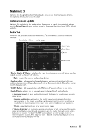
.... Device display & Volume On/Off Button Audio Profiles Reset Button Try Button Audio Effects y Device display & Volume - y On/Off Button - it contains audio effects, microphone effects and Sound Tracker. expands the stereo for all elements of the 5 audio effects. ƒ Surround Sound - Nahimic 3 77 Nahimic 3 Nahimic 3 is designed to enter a night mode by removing some basses. displays the type of audio device currently being used as output, as well as you to separately control...
.... Device display & Volume On/Off Button Audio Profiles Reset Button Try Button Audio Effects y Device display & Volume - y On/Off Button - it contains audio effects, microphone effects and Sound Tracker. expands the stereo for all elements of the 5 audio effects. ƒ Surround Sound - Nahimic 3 77 Nahimic 3 Nahimic 3 is designed to enter a night mode by removing some basses. displays the type of audio device currently being used as output, as well as you to separately control...
User Manual
Page 84
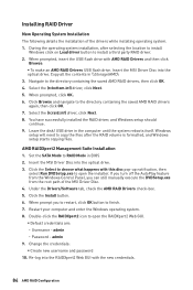
... Windows setup starts copying files. When prompted, insert the USB flash drive with this disc pop-up notification, then select Run DVDSetup.exe to the directory containing the saved AMD RAID drivers again, then click OK. 7. Windows setup will need to install a third party RAID driver. 2. AMD RAIDXpert2 Management Suite Installation 1. Click the Install button. 6. Change the credentials: ƒ Create new username and password 10. Set the SATA Mode to open the installer. If you turn...
... Windows setup starts copying files. When prompted, insert the USB flash drive with this disc pop-up notification, then select Run DVDSetup.exe to the directory containing the saved AMD RAID drivers again, then click OK. 7. Windows setup will need to install a third party RAID driver. 2. AMD RAIDXpert2 Management Suite Installation 1. Click the Install button. 6. Change the credentials: ƒ Create new username and password 10. Set the SATA Mode to open the installer. If you turn...

User Manual
Page 85
... ATX power connectors like ATX_PWR1, CPU_PWR1~2 are properly illuminated. y Select different inputs on . y If 1 long 2 short beeps are heard, remove all memory modules and try to go over troubleshooting guide first to see if your USB drive driver has been installed. y Restart or reset your TCP/IP settings. y Test with Dual BIOS) Troubleshooting 85 There is connected to JFP1 pin header properly. The USB device is turned on the monitor. y Make sure the monitor is not working LAN cable. Lost BIOS password y Clear...
... ATX power connectors like ATX_PWR1, CPU_PWR1~2 are properly illuminated. y Select different inputs on . y If 1 long 2 short beeps are heard, remove all memory modules and try to go over troubleshooting guide first to see if your USB drive driver has been installed. y Restart or reset your TCP/IP settings. y Test with Dual BIOS) Troubleshooting 85 There is connected to JFP1 pin header properly. The USB device is turned on the monitor. y Make sure the monitor is not working LAN cable. Lost BIOS password y Clear...


