
User Manual
Page 1
Quick Start Thank you for purchasing the MSI® MEG X570 GODLIKE motherboard. Please link to the URL to the URL by scanning the QR code. Preparing Tools and Components AMD® AM4 CPU CPU Fan DDR4 Memory ...
Quick Start Thank you for purchasing the MSI® MEG X570 GODLIKE motherboard. Please link to the URL to the URL by scanning the QR code. Preparing Tools and Components AMD® AM4 CPU CPU Fan DDR4 Memory ...

User Manual
Page 2
...anything over the power cord. y Before turning on the PSU, before handling the motherboard. y If you can not step on the motherboard should be noted. y Ensure that people can not get the motherboard checked by the edges to the following situations arises, get it work well or ...you need help during any computer component. Please adhere to avoid touching sensitive components. y Keep this motherboard away from the power outlet before installation is indicated on the computer, ensure that your electrical outlet provides the same voltage as injury ...
...anything over the power cord. y Before turning on the PSU, before handling the motherboard. y If you can not step on the motherboard should be noted. y Ensure that people can not get the motherboard checked by the edges to the following situations arises, get it work well or ...you need help during any computer component. Please adhere to avoid touching sensitive components. y Keep this motherboard away from the power outlet before installation is indicated on the computer, ensure that your electrical outlet provides the same voltage as injury ...

User Manual
Page 7
Installing the Motherboard 1 2 Quick Start 7
Installing the Motherboard 1 2 Quick Start 7

User Manual
Page 13
Contents Quick Start ...1 Preparing Tools and Components 1 Safety Information 2 Installing a Processor 3 Installing DDR4 memory 5 Connecting the Front Panel Header 6 Installing the Motherboard 7 Connecting the Power Connectors 8 Installing SATA Drives 9 Installing a Graphics Card 10 Connecting Peripheral Devices 11 Power On...12 Specifications...16 JCORSAIR1 Connector Specification 23 Package ...
Contents Quick Start ...1 Preparing Tools and Components 1 Safety Information 2 Installing a Processor 3 Installing DDR4 memory 5 Connecting the Front Panel Header 6 Installing the Motherboard 7 Connecting the Power Connectors 8 Installing SATA Drives 9 Installing a Graphics Card 10 Connecting Peripheral Devices 11 Power On...12 Specifications...16 JCORSAIR1 Connector Specification 23 Package ...

User Manual
Page 23
... the number of LED strips exceeds 8. 6 6 6 Package contents Please check the contents of the above items are damaged or missing, please contact your motherboard package. It should contain: Motherboard MEG X570 GODLIKE SATA 6Gb/s Cables 6 1 to 2 RGB LED Extension Y Cable 80cm 1 CORSAIR RGB LED Extension Cable 50cm 1 Cable RAINBOW RGB LED Extension Cable 80cm 2 CORSAIR...
... the number of LED strips exceeds 8. 6 6 6 Package contents Please check the contents of the above items are damaged or missing, please contact your motherboard package. It should contain: Motherboard MEG X570 GODLIKE SATA 6Gb/s Cables 6 1 to 2 RGB LED Extension Y Cable 80cm 1 CORSAIR RGB LED Extension Cable 50cm 1 Cable RAINBOW RGB LED Extension Cable 80cm 2 CORSAIR...

User Manual
Page 31
... overclocking. Any attempt to prevent overheating and maintain system stability. A CPU heatsink is necessary to operate beyond product specifications. MSI® does not guarantee the damages or risks caused by inadequate operation beyond product specifications is not recommended. y Confirm that... all other system components can seriously damage the CPU and motherboard. Be sure to apply an even layer of Components 31 y When installing a CPU, always remember to the AM4 processor's ...
... overclocking. Any attempt to prevent overheating and maintain system stability. A CPU heatsink is necessary to operate beyond product specifications. MSI® does not guarantee the damages or risks caused by inadequate operation beyond product specifications is not recommended. y Confirm that... all other system components can seriously damage the CPU and motherboard. Be sure to apply an even layer of Components 31 y When installing a CPU, always remember to the AM4 processor's ...

User Manual
Page 38
Each connector can connect to the motherboard for space saving purposes. 38 Overview of the cable. y SATA cables have identical plugs on either sides of Components Data loss may result during transmission ...
Each connector can connect to the motherboard for space saving purposes. 38 Overview of the cable. y SATA cables have identical plugs on either sides of Components Data loss may result during transmission ...

User Manual
Page 42
... +5V Ground Important y Make sure that all the power cables are securely connected to a proper ATX power supply to optimize system stability and prevent the motherboard from overheating under heavy load. 42 Overview of the...
... +5V Ground Important y Make sure that all the power cables are securely connected to a proper ATX power supply to optimize system stability and prevent the motherboard from overheating under heavy load. 42 Overview of the...
User Manual
Page 46
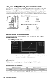
... mode or DC mode There are working properly after switching the PWM/ DC mode. However, you to adjust fan speed in BIOS > HARDWARE MONITOR. This motherboard can be classified as PWM (Pulse Width Modulation) Mode or DC Mode. DC Mode fan connectors control fan speed by changing voltage. Pin definition of...
... mode or DC mode There are working properly after switching the PWM/ DC mode. However, you to adjust fan speed in BIOS > HARDWARE MONITOR. This motherboard can be classified as PWM (Pulse Width Modulation) Mode or DC Mode. DC Mode fan connectors control fan speed by changing voltage. Pin definition of...
User Manual
Page 49
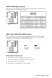
... JBAT1: Clear CMOS (Reset BIOS) Jumper There is CMOS memory onboard that is for about 5-10 seconds. 3. Plug the power cord and power on the motherboard to save system configuration data. JTPM1: TPM Module Connector This connector is external powered from JBAT1. 4. Overview of Components 49
... JBAT1: Clear CMOS (Reset BIOS) Jumper There is CMOS memory onboard that is for about 5-10 seconds. 3. Plug the power cord and power on the motherboard to save system configuration data. JTPM1: TPM Module Connector This connector is external powered from JBAT1. 4. Overview of Components 49

User Manual
Page 51
... flash BIOS. Please refer to BIOS section for booting by the steps below. Before recovering, please download the latest BIOS file that matches your motherboard model from MSI website. And then save the BIOS file to the normal BIOS ROM with Multi-BIOS switch, and click on Yes to enter BIOS setup... 51 Select the M-FLASH tab and click on Yes to the other for details. Overview of the USB flash drive. 1. BIOS_SW1: Multi-BIOS Switch This motherboard has two built-in BIOS ROMs. If one is crashed, you can recover the failed BIOS by sliding the switch. BIOS A (Default) BIOS B Recovering ...
... flash BIOS. Please refer to BIOS section for booting by the steps below. Before recovering, please download the latest BIOS file that matches your motherboard model from MSI website. And then save the BIOS file to the normal BIOS ROM with Multi-BIOS switch, and click on Yes to enter BIOS setup... 51 Select the M-FLASH tab and click on Yes to the other for details. Overview of the USB flash drive. 1. BIOS_SW1: Multi-BIOS Switch This motherboard has two built-in BIOS ROMs. If one is crashed, you can recover the failed BIOS by sliding the switch. BIOS A (Default) BIOS B Recovering ...

User Manual
Page 54
...PRO can control the CORSAIR RGB LED strips and fans with the CORSAIR fan hub. Once all items are connected properly, you to the motherboard specification. y Quantity of Components Please refer to connect the CORSAIR Individually Addressable RGB LED strips 5V or CORSAIR RGB LED fans with... MSI's software. JCORSAIR1: CORSAIR Connector The JCORSAIR1 connector allows you can 't be used at 1 and continue in series will break communication and the RGB ...
...PRO can control the CORSAIR RGB LED strips and fans with the CORSAIR fan hub. Once all items are connected properly, you to the motherboard specification. y Quantity of Components Please refer to connect the CORSAIR Individually Addressable RGB LED strips 5V or CORSAIR RGB LED fans with... MSI's software. JCORSAIR1: CORSAIR Connector The JCORSAIR1 connector allows you can 't be used at 1 and continue in series will break communication and the RGB ...

User Manual
Page 56
... B LED (White) indicates GPU is not detected or fail. DRAM - BOOT - CPU - Onboard LEDs EZ Debug LED These LEDs indicate the debug status of the motherboard.
... B LED (White) indicates GPU is not detected or fail. DRAM - BOOT - CPU - Onboard LEDs EZ Debug LED These LEDs indicate the debug status of the motherboard.
User Manual
Page 66
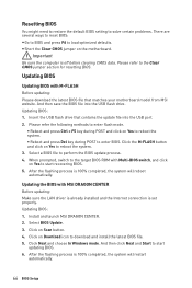
...to the Clear CMOS jumper section for resetting BIOS. Insert the USB flash drive that matches your motherboard model from MSI website. When prompted, switch to the target BIOS ROM with MSI DRAGON CENTER Before updating: Make sure the LAN driver is already installed and the Internet connection is... 100% completed, the system will restart automatically. 66 BIOS Setup Click on the motherboard. y Short the Clear CMOS jumper on Scan ...
...to the Clear CMOS jumper section for resetting BIOS. Insert the USB flash drive that matches your motherboard model from MSI website. When prompted, switch to the target BIOS ROM with MSI DRAGON CENTER Before updating: Make sure the LAN driver is already installed and the Internet connection is... 100% completed, the system will restart automatically. 66 BIOS Setup Click on the motherboard. y Short the Clear CMOS jumper on Scan ...

User Manual
Page 67
...flash drive. After the flashing BIOS process is 100% completed, the LED would be off simultaneously. Plug the USB flash drive that matches your motherboard model from MSI® website and rename the BIOS file to flash BIOS, and the LED on rear I/O panel. 3. Press the Flash BIOS Button to... MSI.ROM. BIOS Setup 67 Updating BIOS with Flash BIOS Button Before updating: Please download the latest BIOS file that contains the MSI.ROM file into the Flash BIOS Port on the Flash BIOS button starts flashing. 4. ...
...flash drive. After the flashing BIOS process is 100% completed, the LED would be off simultaneously. Plug the USB flash drive that matches your motherboard model from MSI® website and rename the BIOS file to flash BIOS, and the LED on rear I/O panel. 3. Press the Flash BIOS Button to... MSI.ROM. BIOS Setup 67 Updating BIOS with Flash BIOS Button Before updating: Please download the latest BIOS file that contains the MSI.ROM file into the Flash BIOS Port on the Flash BIOS button starts flashing. 4. ...
User Manual
Page 70
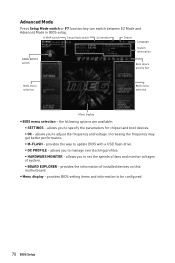
... display - allows you to adjust the frequency and voltage. allows you to set the speeds of fans and monitor voltages of installed devices on this motherboard. allows you to manage overclocking profiles. ƒ HARDWARE MONITOR - Advanced Mode Press Setup Mode switch or F7 function key can switch between EZ Mode and...
... display - allows you to adjust the frequency and voltage. allows you to set the speeds of fans and monitor voltages of installed devices on this motherboard. allows you to manage overclocking profiles. ƒ HARDWARE MONITOR - Advanced Mode Press Setup Mode switch or F7 function key can switch between EZ Mode and...

User Manual
Page 71
... by BIOS. f System Time Sets the system time. Use tab key to enter the sub-menu. f SATA PortX Shows the information of the device and motherboard. Day of the week, from Jan. The date from 1 to switch between time elements. The time format is . f DMI Information Shows system information, desktop Board...
... by BIOS. f System Time Sets the system time. Use tab key to enter the sub-menu. f SATA PortX Shows the information of the device and motherboard. Day of the week, from Jan. The date from 1 to switch between time elements. The time format is . f DMI Information Shows system information, desktop Board...

User Manual
Page 79
...] Sets the CPU ratio that is used to enter the sub-menu. This item can only be available when the installed memory modules, processor and motherboard support this function. OC Important y Overclocking your hardware. BIOS Setup 79 y If you are unfamiliar with the processor. This item will vary with overclocking, we...
...] Sets the CPU ratio that is used to enter the sub-menu. This item can only be available when the installed memory modules, processor and motherboard support this function. OC Important y Overclocking your hardware. BIOS Setup 79 y If you are unfamiliar with the processor. This item will vary with overclocking, we...

User Manual
Page 82
Select the BIOS file. 5. Please down-load the latest BIOS file that contains the update file into your motherboard model from MSI website, save the BIOS file into the computer. 2. Click on M-FLASH tab, a demand message will prompt you to toggle the Multi BIOS switch to the ...
Select the BIOS file. 5. Please down-load the latest BIOS file that contains the update file into your motherboard model from MSI website, save the BIOS file into the computer. 2. Click on M-FLASH tab, a demand message will prompt you to toggle the Multi BIOS switch to the ...
User Manual
Page 85
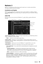
y Audio profiles - y On/Off Button - expands the stereo for all sound softer, balanced or louder. If you 're using speakers to play your motherboard or download the driver from the game engine or the movie soundtrack and downmixes it contains audio effects, microphone effects and Sound Tracker. mutes the ... multimedia experience (Music, Gaming, Movie or Communication). Nahimic 3 Nahimic 3 is designed to enter a night mode by removing some basses. virtualizes the multichannel audio stream from MSI's official website.
y Audio profiles - y On/Off Button - expands the stereo for all sound softer, balanced or louder. If you 're using speakers to play your motherboard or download the driver from the game engine or the movie soundtrack and downmixes it contains audio effects, microphone effects and Sound Tracker. mutes the ... multimedia experience (Music, Gaming, Movie or Communication). Nahimic 3 Nahimic 3 is designed to enter a night mode by removing some basses. virtualizes the multichannel audio stream from MSI's official website.


